
Related Manuals for Extron electronics IP Link Pro xi IPL EXP I/O Series


Summary of Contents for Extron electronics IP Link Pro xi IPL EXP I/O Series
- Page 1 User Guide IP Link Pro xi Products ® IPL EXP I/O Series Control System Expansion Interfaces 68-3490-01 Rev. A 08 21...
- Page 2 Safety Instructions...
- Page 3 Copyright © 2021 Extron. All rights reserved. www.extron.com Trademarks All trademarks mentioned in this guide are the properties of their respective owners. The following registered trademarks (®), registered service marks ( ), and trademarks (™) are the property of RGB Systems, Inc. or Extron (see the current list of trademarks on the Terms of Use page at www.extron.com):...
- Page 4 FCC Class A Notice This equipment has been tested and found to comply with the limits for a Class A digital device, pursuant to part 15 of the FCC rules. The Class A limits provide reasonable protection against harmful interference when the equipment is operated in a commercial environment.
- Page 5 Conventions Used in this Guide Notifications The following notifications are used in this guide: CAUTION: Risk of minor personal injury. ATTENTION : Risque de blessure mineure. ATTENTION: • Risk of property damage. • Risque de dommages matériels. NOTE: A note draws attention to important information. TIP: A tip provides a suggestion to make working with the application easier.
-
Page 7: Table Of Contents
Contents Introduction Ports, Addressing, and Connections ....13 ........... 1 Power Connections ........14 Before You Begin ..........1 Bidirectional Control and Communication What This Guide Covers ......... 1 Connections and Features ......17 Conventions Used in This Guide ..... 1 Unidirectional Control and Important Information You Need Before Communication Connections ....... - Page 8 Firmware Updates ........42 Determining the Firmware Version ..... 42 Using Toolbelt Software ........ 42 Using a Browser ........... 42 Updating the Firmware ........43 Locating and Downloading the Firmware ..43 Installing Firmware ........43 IPL EXP I/O Series • Contents...
-
Page 9: Introduction
Introduction This section covers the following basic information you should know about this guide and the product before installation: • Before You Begin • About Global Configurator • About the IPL EXP Series • About Global Scripter • Application Diagram •... -
Page 10: About The Ipl Exp I/O Series
About the IPL EXP I/O Series The Extron IPL EXP I/O Series control system expansion interfaces make it possible to easily expand the number and variety of ports available in an Extron IP Link Pro xi control system. These expansion interfaces work in conjunction with IPCP Pro xi Series control processors. Once configured, these systems allow users to remotely control, monitor, and troubleshoot AV equipment, including display devices and switchers to integrate Ethernet connection into AV systems. -
Page 11: Features
Features General features Flexible options for device control — Depending on the model, each IPL EXP offers a variety of control ports for RS-232, infrared/serial (IR/S) control, TCP/Ethernet control and monitoring, relays, and either digital I/O (digital input or digital output) or digital I/O with DC power output. -
Page 12: Feature Summary Table
Feature Summary Table The following table provides a summary of models and major features. Features Ports Model Plastic — — — — — — IPL EXP S2 IPL EXP S5 Plastic — — — — — — Plastic — — IPL EXP 200 IPL EXP RIO8 Metal — —... -
Page 13: Device Control
Device Control The system, including the IPCP and the IPL EXP, must be configured in one of the following ways before it will send commands to a projector, display, or other device: • An IR, RS-232, or Ethernet driver file can be downloaded from the Extron website (www.extron.com/download/index.aspx). -
Page 14: Hardware Features And Installation
Hardware Features and Installation This section covers the following material: • Setup Checklist — A checklist of tasks to guide you through installation • Network Communication Setup — A flowchart guide to network settings configuration • Features — Locations and some descriptions of items on the front panel Mounting •... -
Page 15: Mount And Cable All Devices
… Obtain network information for the unit from the network administrator. You also need the following details for each Extron Pro series Ethernet-enabled device: … … DHCP setting (on or off) Subnet mask … … Device (IPL EXP, IPCP Pro, TouchLink Pro, NBP) Gateway IP address LAN IP address …... -
Page 16: Configure Or Program The Control Processor, Expansion Interfaces, Touchpanels, And Network Button Panels
Configure or Program the Control Processor, Expansion Interfaces, Touchpanels, and Network Button Panels … If TouchLink Pro touchpanels are part of the system, start and use GUI Designer to design, save, and build the graphical user interface (GUI) layout for the touchpanels (see the GUI Designer Help File for instructions). NOTE: To redeem (activate) a LinkLicense, go to www.extron.com/llredeem follow the online instructions. -
Page 17: Test And Troubleshoot
… Add the PL EXP expansion interfaces and program their ports. … Add touchpanels and set them up: … Upload the GUI configuration to the Global Scripter project. Program functions, monitors, or schedules to the touchpanels and their … buttons. … Save the project. -
Page 18: Features
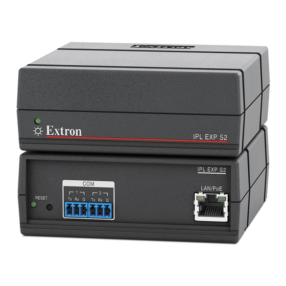
Features This section shows panel features and their locations. Most of the features and LED indications are described and shown in the Ports, Addressing, and Connections section starting on page 13 paired with the descriptions of the corresponding ports. Front Panel Features IPL EXP S2 IPL EXP 200 Power... -
Page 19: Reset Features
Reset Features Reset button and LED — Pressing this recessed button causes various product settings to be reset to the factory defaults. The green Reset LED (rear panel of the IPL EXP S2, IPL EXP S5, IPL EXP 200) or Power LED (front panel of the IPL EXP RIO8) blinks depending on the selected reset mode (see Resetting the Unit on page 29 and the... -
Page 20: Rack Mounting
Rack Mounting The IPL EXP units are one quarter rack wide. Up to four IPL units can be mounted side by side directly onto a rack shelf. Align the threaded holes in the bottom of the IPL EXP with the holes in an Extron RSB 123 rack shelf and fasten the unit Rack Shelf... -
Page 21: Ports, Addressing, And Connections
Mounting to rack rails using a ZipClip Fasten the ZipClip 200 mounting clip to a rack rail using two rack screws ZipClip 200 as shown in the diagram at right. Insert the bottom of the Side of Rack EXP down into the clip, starting with one end. -
Page 22: Power Connections
Power Connections ATTENTION: • Always use a power supply supplied or specified by Extron. Use of an unauthorized power supply voids all regulatory compliance certification and may cause damage to the supply and the unit. • Utilisez toujours une source d’alimentation fournie par Extron ou recommandée. L’utilisation d’une source d’alimentation non autorisée annule toute certification de conformité... - Page 23 Power output (IPL EXP RIO8 only) 12 VDC and 24 VDC power output ports — The IPL EXP RIO8 includes both 12 VDC and 24 VDC output ports for use together with the digital I/O ports to provide power to small accessories. They remain on as long as there is no overload condition. •...
- Page 24 Rear Panel, IPL EXP RIO8 12 VDC and 24 VDC Power Output 2 12V24V G 4 12V24V G Use these ports to power accessories such as occupancy sensors. Total maximum output is 19 watts, if a PoE+ power supply is used to power the IPL EXP RIO8.
-
Page 25: Bidirectional Control And Communication Connections And Features
Bidirectional Control and Communication Connections and Features 3-pole COM ports, RS-232 only All models except the IPL EXP RIO8 include COM ports, which can be used for serial control of a display or other device and to receive status messages from the connected devices. - Page 26 LAN/PoE and LAN/PoE+ (Ethernet) connectors and LEDs To connect the EXP to an Ethernet network (for configuration and control of the EXP and the devices connected to it), plug a cable into one of these RJ-45 sockets and connect the other end of the cable to a power inserter, network switch, hub, router, or PC connected to a local network or the Internet.
- Page 27 Cabling: • For 10Base-T (10 Mbps) networks, use a CAT 3 or better cable. For 100Base-T (max. 155 Mbps) networks, use a CAT 5 or better cable. • Connect the PC that you will use for setup, the LAN port of the EXP , and the control processor and touchpanels to the same Ethernet network.
-
Page 28: Unidirectional Control And Communication Connections
Unidirectional Control and Communication Connections IR/Serial output ports An IPL EXP 200 can use infrared signals or unidirectional RS-232 serial signals to control various devices (up to four per port for IR) via these ports. Set output signal type (IR or serial) during configuration. - Page 29 Relay ports The IPL EXP 200 and IPL EXP RIO8 have relay ports, which also provide control for power, screen or projector lifts, window coverings, and similar items, when trigger events occur. All relays normally open. IPL EXP RIO8 Rear Panels Relays Front Panel •...
-
Page 30: Additional Control Ports
Additional Control Ports Digital I/O (digital input/output) ports (IPL EXP 200, IPL EXP RIO8) To allow the IPL EXP to monitor devices to trigger events, connect switches, sensors, LEDs, relays, or similar items to these ports. Connect physical switches, sensors, LEDs, relays, or similar items to these ports, which can be configured as digital inputs or outputs, with or without +5 VDC pull-up. - Page 31 Digital I/O digital input with pull-up disabled: • Digital input is triggered by an external switch or voltage between the digital • input pin and ground. • Example application, digital input without pull-up: occupancy sensor connection: +5.0 V 1k ohms SW 2 Occupancy Sensor...
- Page 32 • Digital I/O digital input with pull-up enabled: • When the port is configured for pull-up, switch 2 is closed, activating the +5.0 VDC pull-up resistor. • When an external switch closes (shorts to ground, logic low), the port is on and (for the IPL EXP RIO8 front panel only) LED is on.
- Page 33 Digital I/O digital output with pull-up disabled: • When switch 1 closes, the port is on and the front panel LED (IPL EXP RIO8 • only) is on. • When switch 1 opens, the port is off and the front panel LED (IPL EXP RIO8 only) is off.
- Page 34 Digital I/O digital output with pull-up enabled: • When the port is configured for pull-up, switch 2 is closed, activating the • +5.0 VDC pull-up resistor. • When switch 1 closes, the port is on and the front panel LED (IPL EXP RIO8 only) is on.
- Page 35 eBUS port (IPL EXP 200) eBUS is a technology (proprietary bus architecture and serial communication protocol) developed by Extron. It allows many eBUS devices (such as button panels) and accessories (including power and signal hubs) to be connected to a single control processor or expansion interface to expand the capabilities of a control system.
- Page 36 See the following diagram as an example of a system where both an EXP and a supplemental power supply are included in the eBUS topology. EBDB MINI eBUS Connections eBUS DISTRIBUTION HUB Rear Panel • Connect up to four (4) eBUS devices to the (or use eBUS distribution hub (EBDB MINI).
-
Page 37: Resetting The Unit
Resetting the Unit There are six reset modes that are available by pressing the Reset button on the front panel (IPL EXP RIO8) or rear panel (all other models). The Reset button is recessed, so use a pointed stylus, ballpoint pen, or Extron Tweeker to access it. See the reset modes table below and on the next pages for a summary of the modes. - Page 38 IPL EXP I/O Series Expansion Interface Reset Mode Summary Use This Activation Result Mode to... Reset IP To reset all IP settings: Reset All IP Settings mode: settings and Press and hold the Reset button until the Reset or Power Turns DHCP off. •...
-
Page 39: Software-Based Configuration And Control
Software-Based Configuration and Control This section of the guide is divided into the following topics: Configuration and Control: An Overview • • Basic Setup Steps: a Guide to this Section and Other Resources Downloading the Software and Getting Started • •... -
Page 40: Basic Setup Steps: A Guide To This Section And Other Resources
Basic Setup Steps: a Guide to this Section and Other Resources NOTE: GC projects can be created offline and uploaded to the hardware at a later date. Follow the steps in Setup Checklist starting on page 6. The overall process for setting up a control processor using GC is as follows: Within Global Configurator Configure the IP settings... -
Page 41: Downloading The Software And Getting Started
Downloading the Software and Getting Started GC software updates and a large variety of device drivers can be downloaded from the Download page on the Extron website (www.extron.com/download/index.aspx). When you locate the desired software or driver package, follow the on-screen directions to download and install it. -
Page 42: Obtaining Control Drivers
For software, click on the link for the specific software that you need. A software product page opens that provides a description of the software package, a list of system requirements, a list of features, and access to the release notes, in addition to a download link. -
Page 43: Things To Do After Installing Gc And Before Starting A Project
Things to Do After Installing GC and Before Starting a Project • Read the Global Configurator Help File, included with the software, for details and step- by-step procedures on how to start a GC Professional or GC Plus project and perform basic setup tasks for a control processor. The help file provides a wealth of information on settings and how to use the software. -
Page 44: Troubleshooting
Troubleshooting Turn on the input devices (DVD players, Blu-ray players, PCs, and other sources), output devices (display screens, projectors), the control processor, and the PC and touchpanel or eBUS button panels. Touch a configured button on the touchpanel or eBUS button panel. If an input or output AV device cannot be remotely controlled (does not respond as expected), check the following: •... -
Page 45: Device Control Connections And Configuration
If contact is established with the unit, but the IPL EXP web pages cannot be accessed by your browser program, verify (via an Internet network options or preferences menu) that your browser is configured for direct network connection and is not set up to use a proxy server. -
Page 46: Reference Information
Reference Information This section of the guide includes the following reference items: • Network Port Requirements and Licensed Third-Party Software File Types: a Key to Extron-specific File Names • Secure Sockets Layer (SSL) Certificates • • IEEE 802.1X Certificates SNMP •... -
Page 47: Secure Sockets Layer (Ssl) Certificates
.glta — This is a GUI layout template. • • .gs – This is a Global Scripter project file. Secure Sockets Layer (SSL) Certificates Extron control processors and expansion interfaces ship with factory-installed SSL certificates created by Extron. If you want or are required to use a different SSL certificate at your installation site, then you can use system utilities in the Toolbelt software to change the SSL certificate at any time. -
Page 48: Ieee 802.1X Certificates
IEEE 802.1X Certificates IEEE 802.1X is a standard that enables port-based network access control via an authentication server. The protocol requires that all devices must be authenticated before gaining privileges to access the secure part of the network. The Extron implementation of 802.1X supports PEAP - MSCHAPV2 and EAP - TLS methods of authentication. -
Page 49: Private Key File Requirements
Private Key File Requirements Private key files are required only when employing machine certificates. Follow these requirements for creating a private key: • Its file name consists of the following types of valid characters: Alphanumerical (A-Z, a-z, 0-9) characters • •... - Page 50 Firmware Updates If the need arises, you can replace the IPL EXP firmware. This section covers the following firmware-related topics: • Determining the Firmware Version • Updating the Firmware Determining the Firmware Version There are several ways to check which firmware version the control processor is using: View the device information in Toolbelt.
- Page 51 Updating the Firmware Firmware upgrade tools require the PC and the control processor to both be connected to an Ethernet network. The instructions for updating the IPL EXP firmware assume you have installed the appropriate software on your PC first. NOTES: •...
- Page 52 Extron Warranty Extron warrants this product against defects in materials and workmanship for a period of three years from the date of purchase. In the event of malfunction during the warranty period attributable directly to faulty workmanship and/ or materials, Extron will, at its option, repair or replace said products or components, to whatever extent it shall deem necessary to restore said product to proper operating condition, provided that it is returned within the warranty period, with proof of purchase and description of malfunction to: USA, Canada, South America,...
Need help?
Do you have a question about the IP Link Pro xi IPL EXP I/O Series and is the answer not in the manual?
Questions and answers