
Related Manuals for Extron electronics IPL T S Series


Summary of Contents for Extron electronics IPL T S Series
- Page 1 User Guide IP Link IPL T S Series IP Link Ethernet Control Interfaces 68-1218-01 Rev. G 12 19...
- Page 2 Safety Instructions Safety Instructions • English Istruzioni di sicurezza • Italiano AVVERTENZA: Il simbolo, , se usato sul prodotto, serve ad WARNING This symbol, , when used on the product, is intended to avvertire l’utente della presenza di tensione non isolata pericolosa alert the user of the presence of uninsulated dangerous voltage within the all’interno del contenitore del prodotto che può...
- Page 3 Copyright © 2016-2020 Extron Electronics. All rights reserved. www.extron.com Trademarks All trademarks mentioned in this guide are the properties of their respective owners. The following registered trademarks ( ® ), registered service marks ( ), and trademarks ( ) are the property of RGB Systems, Inc. or Extron Electronics (see the current list of trademarks on the...
- Page 4 FCC Class A Notice This equipment has been tested and found to comply with the limits for a Class A digital device, pursuant to part 15 of the FCC rules. The Class A limits provide reasonable protection against harmful interference when the equipment is operated in a commercial environment.
- Page 5 Conventions Used in this Guide Notifications The following notifications are used in this guide: ATTENTION: • Risk of property damage. • Risque de dommages matériels. NOTE: A note draws attention to important information. Software Commands Commands are written in the fonts shown here: ^AR Merge Scene,,0p1 scene 1,1 ^B 51 ^W^C.0 [01] R 0004 00300 00400 00800 00600 [02] 35 [17] [03] *X1&* X2)* X2#*...
-
Page 6: Table Of Contents
Configuration using Embedded Web Pages ..21 About This Guide ..........1 Connecting Via the Web Server Pages ..21 About the IPL T S Series Interface ....... 1 System Status Page ........22 Features .............. 3 Configuration page ........22 File Management Page ...... - Page 7 IPL T S Series • Contents...
-
Page 8: Introduction
The Extron IPL T S Series interface devices integrate network connectivity into audio/ video (AV) systems. Installing an IPL T S Series interface into an AV network gives users the ability to remotely monitor and control projectors, flat-panel displays, switchers, and other serially-controlled devices. - Page 9 Compatibility with the free GlobalViewer application which provides a graphical user • interface with which to remotely monitor and control your AV network devices The IPL T S Series interface devices support the following network protocols: • DHCP − Dynamic host configuration protocol •...
-
Page 10: Features
• DataViewer (or a standard Telnet client application) The IPL T S series requires no centralized processor to operate within a system. Multiple mounting options — Can be mounted under a desktop or podium, on a projector mount, or on a rack shelf. -
Page 11: Installation And Operation
Appropriate consideration of equipment nameplate ratings should be used when addressing this concern. IPL T S Series • Installation and Operation... -
Page 12: Mounting Options
Mounting Options All units are easily mounted in a rack, under a desk or podium, or on a projector mount. Mounting kits and IPL T S Series device compatibility are shown in the table below. Mounting Type MBU 125 Under-desk mount •... -
Page 13: Furniture Or Projector Mounting
To mount an IPL T S Series device with a projector (see figure 4): If present, remove the rubber feet from the bottom of the IPL T S unit. -
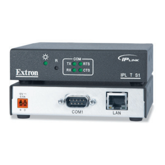
Page 14: Rear Panel Features And Cabling
Une alimentation avec une polarité de tension incorrecte peut endommager la source d’alimentation ainsi que l’interface. Il est essentiel d’identifier une connexion négative du cordon d’alimentation au niveau des stries sur les parties latérales du cordon. IPL T S Series • Installation and Operation... - Page 15 (5 mm) Max. Power Supply Output Cord Orange Captive Screw Connector Ground +12 VDC Power Supply Output Cord External Power Supply (12 VDC, 1 A ) AC Power Cord Figure 9. Power Connector Wiring IPL T S Series • Installation and Operation...
-
Page 16: Ethernet/Lan
1 and 2 (IPL T S2) or serial ports 3 through 6 (IPL T S6) connections. Pacing and handshaking are not supported via the captive screw connectors. IPL T S Series • Installation and Operation... - Page 17 COM3 — 9-pin D connector for serial port 3 (S4 only) COM4 — 9-pin D connector for serial port 4 (S4 only) IPL T S Series interface devices can be used to control display devices, switchers, and other AV equipment via an RS-232/RS-422/RS-485 connection.
-
Page 18: Identification
IPL T S6 Front Panel Power LED — A green LED lights to indicate that the interface is receiving power. Reset button (recessed) — A multi-function reset button (see Resetting the unit on page. IPL T S Series • Installation and Operation... -
Page 19: Resetting The Unit
(blinks) and puts the unit in a different mode. The Mode 5 LED blinks three times, the third blink indicating that it is the last mode. The following modes are separate functions, not a continuation from Mode 1 to Mode 5. IPL T S Series • Installation and Operation... - Page 20 (IR/RS-232). • Removes button configurations. • Resets all IP options. • Removes scheduling settings. • Removes/clears all files from switcher. The Reset LED flashes 4 times in quick succession during the reset. IPL T S Series • Installation and Operation...
-
Page 21: Connection And Configuration
From your PC, launch a web browser and type in the IP address previously set up on the IPL T S. If this has not been set up, see Setting the Internet Protocol (IP) Address on page 15. This displays the System Status web page. IPL T S Series • Connection and Configuration... -
Page 22: Serial Connection
Address Resolution Protocol (ARP) command Before you begin: Obtain a valid IP address for your IPL T S Series device from your AV system network administrator. Write down the unit MAC address (a 12-digit number) found on a label on the rear panel of the unit (for example, 00-05-A6-01-0A-74). -
Page 23: Setting The Ip Address Using Global Configurator
The first six digits (00-05-0A) are pre-populated, and identify this unit as an Extron device. You only need to enter the final six digits. Dashes between digits are auto-filled. Click the Set button. The Auto Configure Successful dialog box opens. Click OK. IPL T S Series • Introduction... -
Page 24: Setting The Ip Address Using Embedded Web Pages
Record the current IP address, subnet mask, default gateway and DHCP settings. You will need this information later to return the PC to its original TCP/IP settings. IP Address: Subnet Mask: Enter the following: IP address: 192.168.254.253 Subnet mask: 255.255.0.0 Default gateway: <blank> Click OK. IPL T S Series • Introduction... - Page 25 The new IP address and subnet mask are assigned to the device, and the web browser connection is immediately lost. The device, with its new IP address and subnet mask is now ready to be connected to your AV network. Figure 21. web Server System Settings Screen IPL T S Series • Introduction...
-
Page 26: Setting The Ip Address Using The Arp Command
To confirm the new IP address is active, perform a ping command to the new IP address. example: C:\>ping 10.13.197.64 If the IP address setting was successful, the device replies 3 or more times: Reply from <IP address>: bytes=32 time <1ms TTL=64 IPL T S Series • Introduction... -
Page 27: Configuration Using Global Configurator
AV devices in multiple locations. Serial ports on the IPL T S Series devices can be configured using GC. Global Configurator is available for free from www.extron.com. -
Page 28: Configuration Using Embedded Web Pages
Connecting Via the Web Server Pages To connect to an IPL T S Series device via its web server pages: Open a web browser on a local PC. -
Page 29: System Status Page
Configuration page The Configuration page has five sub-pages, which are described below. System Settings The System Settings page grants access to view and change: • IP Settings • Date/Time Settings Figure 27. System Settings Screen IPL T S Series • Introduction... - Page 30 Passwords Screen To clear a password, enter a single space, repeat the entry in the re-enter password field, then click the Submit button. If no administrator password is present, the user password is not saved. IPL T S Series • Introduction...
- Page 31 Figure 30. Email Alerts Screen Firmware Upgrade The Firmware Upgrade page reports the current firmware level, and provides the capability to browse to and upload a new firmware file. Figure 31. Firmware Upgrade Screen IPL T S Series • Introduction...
-
Page 32: File Management Page
Click the Control Software icon. Scroll to the description of DataViewer. Click the Download link in the far right column. Complete the Personal Information form. Click the Download DVSW1x2x0x4.exe button. Follow the remaining system prompts. IPL T S Series • Introduction... - Page 33 Communication Setup Dialog Box The DataViewer application opens (see figure 33). See the DataViewer help file for information on sending commands to the IPL T S Series device, and viewing the responses in the DataViewer user interface. IPL T S Series • Introduction...
-
Page 34: Communication And Control
NOTE: With Telnet you can use either the Escape commands with the carriage return or the W commands with the pipe (|) character. With the web browser you are required to use the W commands and the pipe character. IPL T S Series • Communication and Control... -
Page 35: Symbol Definitions
Asterisk character (which is a command character, not a variable) NOTE: For commands and examples of computer or device responses used in this guide, the character 0 is the number zero and O is the capital letter o. IPL T S Series • Communication and Control... - Page 36 To find the decimal equivalent of the ASCII character, add the row heading and column heading numbers together. space “ & ’ < > ‘ LF = line feed CR = carriage return ( Esc = escape Del = delete IPL T S Series • Communication and Control...
-
Page 37: Command And Response Table
= Parameter to set either Length of message to receive or Delimiter value. If length delimited, use L, where is the length of the incoming message in bytes. If character delimited, use xxD, where xx is the decimal ASCII value of the delimiting character. IPL T S Series • Communication and Control... - Page 38 = Port type: = RS-232 = RS-422 = RS-485 = Flow control: Hardware Software None (only the first letter is needed) 0–1000 = Data pacing (specified in milliseconds between bytes): (default = IPL T S Series • Communication and Control...
- Page 39 = IP connection timeout period in seconds. Each step is specified in 10-second intervals (1 - 65000, default = 30 = 300 seconds). If no data is received during the specified period, the Ethernet connection closes. Responses are returned with leading zeros. IPL T S Series • Communication and Control...
- Page 40 In this example the current firmware version is 1.01, the IP Link kernel version is 1.31, for the IPL T S device, dated 28 February, 2005. n.nn = Unit firmware version (to the second decimal place) KEY: IPL T S Series • Communication and Control...
- Page 41 (first line of the file = the subject, the rest = the body of the e-mail). 1.eml, 2.eml, ... 64.eml) NOTE: E-mail files must have a file extension of .eml. The first line of the file is the subject, the rest is the body of the e-mail. IPL T S Series • Communication and Control...
- Page 42 NOTE: The factory configured passwords for all accounts on this device have been set to the device serial number. In the event of an absolute system reset, the passwords convert to the default, which is no password. IPL T S Series • Communication and Control...
- Page 43 = An e-mail account password (for SMTP authentication) of up to 31 characters. Do not use commas. This parameter is optional during setup. In a response, instead of the actual password, = Default name: a combination of the model-name and the last 3 pairs of the MAC address (that is, IPL-T-S2-00-02-3D) IPL T S Series • Communication and Control...
- Page 44 = Hardware (MAC) address: the four most significant hex nibbles converted into a single 16-bit decimal number. = Hardware (MAC) address: the eight least significant hex nibbles converted into single 32-bit decimal number. IPL T S Series • Communication and Control...
- Page 45 = Reading password: responds as empty if no password is set, and 4 asterisks (****) if password exists. = Connection security level: 0 = not logged in, 1 = user, 2 = administrator IPL T S Series • Communication and Control...
- Page 46 W0MD Pmd00000 port View Direct Access port {port#} Duplicate port# assignments are not permitted (for example, Telnet and web cannot be the same) and result in an E13 (invalid parameter) response. NOTE: IPL T S Series • Communication and Control...
- Page 47 Erase user-supplied filenameEF WfilenameEF Del•filename web page/file 24 28 Erase current directory W/EF and its files 24 28 Erase current directory //EF W//EF and subdirectories 24 28 List files from current directory IPL T S Series • Communication and Control...
- Page 48 NOTE: This command is intermediate between the ZXXX and ZQQQ commands. It is an absolute system reset excluding IP settings (IP address, subnet mask, gateway IP address, unit name, DHCP settings, port mapping). This allows you to maintain communication with the device. This reset is recommended after a firmware update. It erases the file system. IPL T S Series • Communication and Control...
- Page 49 The factory configured passwords for all accounts on this device have been set to the device serial number. In the event of an absolute system reset, the passwords convert to the default, which is no password. IPL T S Series • Communication and Control...
-
Page 50: Customization
Server Side Include Using the Host SIS command SIS Command "--> <!--#echo var=" SIS command to be processed by the IP Link *Type with no spaces. Figure 35. Example of an SSI Host Command IPL T S Series • Communication and Control... -
Page 51: Query String
In the figure above, the data string that follows the pipe ( | ) symbol is sent to the attached controlled device on serial port #2. This string instructs an attached Extron switcher to change to input #1. IPL T S Series • Communication and Control... -
Page 52: Code Examples
This example requires an Extron Crosspoint 84HVA connected to IPL T S2 serial port #1. <p> Part Number: <b>N60-337-01%0D%0A</b> <br> Connection Info: <b>V08X04 A08X04 Exe0%0D%0A</b> <br> Firmware Version: <b>Ver2.02%0D%0A</b> </body> </html> Figure 40. Resulting HTML Source Code Served by an IP Link web Server IPL T S Series • Communication and Control... - Page 53 HTML Source Code Showing Multiple Hyperlinks Using Query Strings Figure 43. Browser View of Previous HTML Source Code NOTE: Before attempting to develop new web pages, the user should have a working knowledge of JavaScript, HTML, and SSI. IPL T S Series • Communication and Control...
-
Page 54: Url Encoding
URL syntax. Only encode unsafe characters (defined below) in your URLs. The following table lists reserved characters. Characters Dollar & Ampersand Plus Comma Forward slash / virgule Colon Semi-colon Equal Question mark “At” symbol IPL T S Series • Communication and Control... -
Page 55: Advanced Serial Port Control
AV device, as shown in the following figure. Any serial port on an IPL T S interface can be configured as a pass-through connection to another serial port on the same device. IPL T S Series • Communication and Control... -
Page 56: Direct Port Access (Ports 2001 Through 2006)
Click the TCP/IP tab on the Communication Setup dialog box. Complete the fields with the appropriate IP address and the TCP/IP port number (2001-2006), as shown in figure 45. NOTE: A password is not required for direct port access. IPL T S Series • Communication and Control... -
Page 57: Serial Bridging
To use serial bridging, two IPL T S devices (one local and one remote) must be enabled to communicate with each other, providing PC or controller access to a remote AV device. Hardware connection To set up the hardware for serial bridging: IPL T S Series • Communication and Control... - Page 58 The Port Settings page appears, as shown in the figure below. Choose the serial port that you wish to communicate through. Under Serial Bridging, choose the On radio button to activate serial bridging mode. IPL T S Series • Communication and Control...
-
Page 59: Troubleshooting
(in the Options or Preferences menu) that your web browser is configured for direct network connection and is not set up to use a proxy server. If you are still experiencing problems, call the Extron S Sales & Technical Support Hotline. IPL T S Series • Communication and Control... - Page 60 Extron Electronics makes no further warranties either expressed or implied with respect to the product and its quality, performance, merchantability, or fitness for any particular use. In no event will Extron Electronics be liable for direct, indirect, or consequential damages resulting from any defect in this product even if Extron Electronics has been advised of such damage.
Need help?
Do you have a question about the IPL T S Series and is the answer not in the manual?
Questions and answers