
Subscribe to Our Youtube Channel
Related Manuals for Extron electronics IPL T PC1


Summary of Contents for Extron electronics IPL T PC1
- Page 1 User Guide IP Link ® IPL T PC1 IPL T PC1i IP Link Power Control Interfaces 68-738-10 Rev. B 09 11...
- Page 2 Safety Instructions • English Warning Power sources • This equipment should be operated only from the power source indicated on the product. This This symbol is intended to alert the user of important operating and equipment is intended to be used with a main power system with a grounded (neutral) conductor. The third maintenance (servicing) instructions in the literature provided with the (grounding) pin is a safety feature, do not attempt to bypass or disable it.
- Page 3 FCC Class A Notice This equipment has been tested and found to comply with the limits for a Class A digital device, pursuant to part 15 of the FCC Rules. Operation is subject to the following two conditions: This device may not cause harmful interference. This device must accept any interference received, including interference that may cause undesired operation.
- Page 4 Conventions Used in this Guide Notifications In this user guide, the following are used: WARNING: A warning warns of things or actions that might cause injury, death, or other severe consequences. CAUTION: A caution indicates a potential hazard to equipment or data. NOTE: A note draws attention to important information.
-
Page 5: Table Of Contents
Contents Introduction Using the IPL T PC1 Web Pages ......22 ............1 Viewing the System Status ......23 About this Guide ..........1 Using the Configuration Pages ...... 24 About the IPL T PC1 ..........1 Configuring the RS-232 Port and the AC Features .............. - Page 6 IPL T PC1 • Contents...
-
Page 7: Introduction
Introduction This section provides an overview of the Extron IPL T PC1 and IPL T PC1i IP Link Power ® Control Interfaces, and describes their features features. Topics covered in this section are: About this Guide • • About the IPL T PC1 Features •... - Page 8 Multiple mounting options — The PC1 can be placed on a tabletop, for which four feet are provided and can be attached. Optional hardware for mounting the unit under a desktop or podium or on a rack shelf is not included, but may be ordered separately. IPL T PC1 • Introduction...
-
Page 9: Application Diagram
Application Diagram The following application diagram shows an example of how devices can be connected to the IPL T PC1 or the IPL T PC1i. Remote User Plasma Control and Display Administrator AC Power Monitoring Extron RS-232 IR Emitter TCP/IP... -
Page 10: Installation And Rear Panel
Rear Panels Connecting Cables • Installation Overview To install and set up an IPL T PC1 interface: Disconnect power from the PC1 interface and the output device (plasma display, VCR, projector, and so forth). If desired, mount the PC1 interface (see “Mounting the IPL T PC1... -
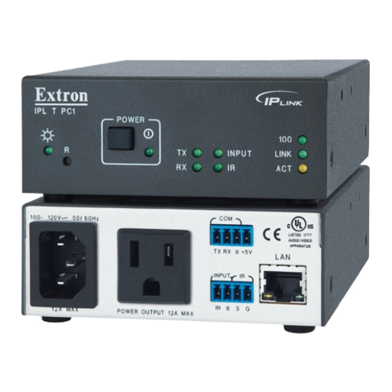
Page 11: Rear Panels
RJ-45 computer. Port Link LED — This green LED lights to indicate a good network • Link connection. Activity Activity LED — This yellow LED blinks to indicate network • activity. IPL T PC1 • Installation and Rear Panels... -
Page 12: Connecting Cables
Output power receptacle — Connect the power cord from an output device to this female 3-prong Edison (IPL T PC1) or IEC (IPL T PC1i) power output receptacle. Connecting Cables Connect cables to the rear panel connectors as outlined below. - Page 13 Wire your display device as described in its communication sheet. You can also access the Communication Sheets via the Global Configurator software (see the IPL T PC1 Setup Guide for information on using GC3.2). Connecting the Display Device To connect the display device to the PC1: Wire an RS-232 cable to the provided 4-pole captive screw connector, as described below.
-
Page 14: Wiring The Local Area Network (Lan) Port
Input Connector Figure 7. Wiring for IR Control via an IR Emitter NOTE: Place the head of the IR emitter over or directly adjacent to the IR receiver of the controlled device. IPL T PC1 • Installation and Rear Panels... -
Page 15: Wiring The Contact Input Port
Wiring the Contact Input Port The IPL T PC1 contact closure Input port can be connected to any device providing a closure to ground (closed = logic 1 and open = logic 0). The contact input is connected to 5 VDC via a 1k ohm pull-up resistor and must be wired with a ground. -
Page 16: Front Panel Features And Operation
Front Panel Features and Operation This section contains a description of the IPL T PC1 and IPL T PC1i front panel features and instructions for setting up the PC1 using the front panel. The following topics are discussed: • Front Panel Features •... -
Page 17: Setting Up The System Using The Front Panel
CAUTION: Some devices, such as projectors, need a cool-down period to power off safely. Use RS-232 or IR commands to power these devices. IPL T PC1 • Front Panel Features and Operation... -
Page 18: Front Panel Security Lockout (Executive Mode)
3 seconds, and with each pulse, the PC1 goes into a different reset mode. For mode 5, the LED blinks three times, indicating that it is the last mode. • The reset modes are separate functions, not a progression from mode 1 to mode 5. IPL T PC1 • Front Panel Features and Operation... -
Page 19: Mode 1
NOTE: If you do not enter the three plus (+) signs within 2 seconds of the momentary press of the Reset button, the RS-232 port reverts to a device control port. IPL T PC1 • Front Panel Features and Operation... -
Page 20: Mode 3
Performs a complete reset to factory defaults (except for the firmware). Purpose and notes Mode 5 is useful if you want to start over with control software configuration and to replace events. IPL T PC1 • Front Panel Features and Operation... -
Page 21: Html Configuration And Control
Global Configurator Software • The IPL T PC1 must be configured before use in order for it to control other devices. In addition to using the button on the PC1 front panel, you can configure and control the PC1 via any computer attached to a LAN. -
Page 22: Setting Up And Configuring The Pc1 Using Arp
Ping is a utility or diagnostic tool that tests network connections. It is used to determine if the host has an operating connection and is able to exchange information with another host. IPL T PC1 • HTML Configuration and Control... -
Page 23: Setting Up And Configuring The Pc1 Using A Web Browser
If you use an existing Ethernet LAN intranet, your network administrator can provide you with a unique IP address for the PC1 or confirm whether you need to set up the PC1 for DHCP (Dynamic Host Configuration protocol) to have an address assigned automatically. IPL T PC1 • HTML Configuration and Control... -
Page 24: Setting Up The Computer For Ip Communication
Open the Network Connections page as follows: From the Start menu, select My Network Places From the side-bar menu, select connections. Network Tasks View Network Right-click , then select Local Area Connection Properties Figure 12. Network Connections Window IPL T PC1 • HTML Configuration and Control... - Page 25 Use the following IP address Enter the following values as shown below: IP address: 192.168.254.253 Subnet mask: 255.255.0.0 Default gateway: Blank or 0.0.0.0 (The temporary IP address differs from the PC1 factory default by 1 digit.) IPL T PC1 • HTML Configuration and Control...
-
Page 26: Configuring The Ipl T Pc1 Using A Web Browser
NOTE: Both your computer and the PC1 must be connected to the same LAN. Configuring the IPL T PC1 Using a Web Browser The default web pages that are preloaded on the PC1 are compatible with popular web browsers such as Internet Explorer (version 5.5 or higher). - Page 27 (see the addresses you wrote down in step 4 of the “Setting up the Computer for IP communication” procedure, earlier in this section.) You are now able to access the PC1 web pages to configure the front panel. IPL T PC1 • HTML Configuration and Control...
-
Page 28: Using The Ipl T Pc1 Web Pages
PC1 IP address, followed by /nortxe_index.html Example: 10.26.188.44/norte_index.html See the IPL T PC1 Setup Guide, delivered with your PC1, for information on using Global Configurator. NOTE: If a password has been set, the Enter Network Password dialog box opens. If no password has been set, the PC1 web page opens, displaying the System Status page. -
Page 29: Viewing The System Status
Changes must be made via the Configuration web pages or SIS “SIS Programming and Control”). Personnel who have user programming commands (see access can view this page but cannot access the Configuration or File Management pages. Figure 17. System Status Screen IPL T PC1 • HTML Configuration and Control... -
Page 30: Using The Configuration Pages
PC1 or the settings submitted most recently. Enter your new information in the IP Settings section, or select the date and time from the menus in the Date/Time Settings section, as described in the following sections. IPL T PC1 • HTML Configuration and Control... - Page 31 : Select hours, minutes, and am or pm from the menus. Time : From the pull-down menu, select the time zone for the location of the PC1 • Zone (number of hours offset from Greenwich mean time). IPL T PC1 • HTML Configuration and Control...
-
Page 32: Configuring The Rs-232 Port And The Ac Receptacle
(connected to ground). If is selected, the contact is open (not connected to ground). NOTE: You cannot make changes in this field; it only reflects the condition of the port. IPL T PC1 • HTML Configuration and Control... - Page 33 , and so forth) before uploading it via File 1.eir 2.eir Management. When the driver is displayed on the IR Drivers page, its device name also is displayed. Figure 20. IR Drivers Page IPL T PC1 • HTML Configuration and Control...
- Page 34 The Passwords screen allows you to assign passwords to the administrator and user access levels. The administrator password gives access to all IPL T PC1 web pages, enabling the administrator to configure the PC1. The user password provides access only to the System Status web page. If you are logged in as user, you see only the tab with the System Status page.
- Page 35 , or both fields, delete Re-enter Admin Password Re-enter User Password the characters that are there, and press the <Spacebar> to enter a space. Click Submit NOTE: Deleting the administrator password also deletes the user password. IPL T PC1 • HTML Configuration and Control...
- Page 36 Address Edit Save Enter your mail server IP address and your domain name in the appropriate fields. (This information is available from your network administrator.) Click to save the information. Save IPL T PC1 • HTML Configuration and Control...
- Page 37 Mail IP Address field to save your user name and password. To remove SMTP authentication requirement, click , deselect the Edit SMTP check box, then click Authentication Required Save IPL T PC1 • HTML Configuration and Control...
-
Page 38: Upgrading Firmware
The uploaded file must have the file extension .S19 NOTE: The PC1 uses the same firmware as the IPL T PC1. However, it does not accept other firmware files, such as the files for the IP Link S Series. - Page 39 Firmware Upgrade screen. To verify that the new version was uploaded, click the Status tab to view the System Status screen. When you return to the Firmware Upgrade screen, the new version number is displayed there also. IPL T PC1 • HTML Configuration and Control...
- Page 40 To close the Set Schedule For section without saving your entries in it, click Refresh the bottom of the screen. • If you want to clear all power and executive mode settings from the schedule, click Clear Schedule , at the bottom of the screen. IPL T PC1 • HTML Configuration and Control...
- Page 41 Set Schedule For section. The settings you entered appear in the Current Schedule in the Receptacle 1 section. Repeat steps 1 through 4 for any additional power settings you want to make. IPL T PC1 • HTML Configuration and Control...
- Page 42 The settings you entered appear on the Current Schedule in the Executive Mode section. Repeat steps 1 through 4 as needed to specify lock mode settings for other days. NOTE: You cannot set Receptacle On and Off for the same time. IPL T PC1 • HTML Configuration and Control...
- Page 43 If you do not want to make selections in the remaining Set Schedule For section, click to close the section. Refresh Repeat steps 1 through 4 for any additional days that you want to schedule. IPL T PC1 • HTML Configuration and Control...
-
Page 44: Managing Files
Uploading files to the web page The IPL T PC1 has approximately 7.25 MB of space for IR drivers, custom web pages, and other user files to be uploaded. The Bytes Left field shows how much user space remains for uploading files. - Page 45 GMT time, and the button returns to its original state. (Files are listed separately under headings of their extensions.) Adding a directory To add a directory or folder to the IPL T PC1 file system: Enter a name for the directory in the field, following the slash (...
-
Page 46: Custom Web Pages
Custom Web Pages On the IPL T PC1, custom web pages are supported. You can determine the layout and appearance of the pages displayed on your screen. Server side includes (SSIs) enable you to obtain information from the unit and display the information on web pages. Query strings... - Page 47 Notice, in the figure below, that the commands executed by the PC1 in response to SSI references have been replied to, and were implemented when the web page was served to the browser. Figure 36. Browser View of Previous HTML Source Code IPL T PC1 • HTML Configuration and Control...
- Page 48 Only encode unsafe characters (defined in the table in the next section) in your URLs. The following table lists reserved characters. Character Hexadecimal Decimal Dollar & Ampersand Plus Comma Forward slash or virgule Colon Equal Question mark “At” symbol IPL T PC1 • HTML Configuration and Control...
-
Page 49: Accessing And Using Telnet (Port 23)
From your desktop Start menu, select , then enter Telnet , then click . The Telnet program starts (see the figure below). Figure 38. Telnet Command Prompt At the command prompt, enter open IPL T PC1 • HTML Configuration and Control... - Page 50 (power on) or 1*0PC (power off). See the “SIS Programming and Control” section for more information on entering SIS commands. When you are finished entering commands to the interface, enter Ctrl+] at the command prompt to exit Telnet. IPL T PC1 • HTML Configuration and Control...
-
Page 51: Troubleshooting
PC1 (see “Setting Up and Configuring the PC1 Using ARP”). If the PC1 is connected and communicating, you receive the following response to your ping command: Figure 40. Successful Ping Command Response IPL T PC1 • HTML Configuration and Control... -
Page 52: Global Configurator Software
Follow the instructions on the subsequent screens to install GC3.3 on your computer. For instructions on using the GC3.3 software with the PC1, see the IPL T PC1 Setup Guide, provided with the PC1, and to the Global Configuration 3.3 help program, accessible from the GC3.3 main screen. -
Page 53: Sis Programming And Control
This section provides instructions on using the Extron Simple Instruction Set (SIS) commands, which you can use to set up and control the IPL T PC1 from a host computer or other control system attached to the rear panel LAN port. The following topics are discussed: •... -
Page 54: Password Information
(privilege violation) response if you are not logged in at the administrator level. commands that may yield an (invalid event number) response. commands that may give an (file not found) response. IPL T PC1 • SIS Programming and Control... -
Page 55: Using The Command And Response Table
• In either method, Data = Data that will be directed to a specified port and must be hex encoded if non-alphanumeric. IPL T PC1 • SIS Programming and Control... -
Page 56: Symbol Definitions
. Leading zeros in each of four fields are optional in setting values, and they are suppressed in returned values. = E-mail domain name (for example: extron.com) Power-up delay between ports in 1/3-second increments. 1-255 permitted. (Default is 3, which equals 1 second.) IPL T PC1 • SIS Programming and Control... - Page 57 Hawaii, American Samoa, Guam, Puerto Rico, the Virgin Islands, the eastern time zone portion of the state of Indiana, and the state of Arizona (excluding the Navajo Nation). 0 = off or ignore 1 = U. S. 2 = Europe 3 = Brazil IPL T PC1 • SIS Programming and Control...
- Page 58 133 = creation date 134 = comments 137 = user file name (descriptive name given to the file by the user) NOTE: 0 and numbers greater than 127 can return information only. IPL T PC1 • SIS Programming and Control...
- Page 59 1440 = clear schedule Example: 1439 = 11:59 Use the following formula (in 24-hour time format): (hour x 60) + minutes = time in minutes X71# Power receptacle name (12 characters maximum) IPL T PC1 • SIS Programming and Control...
-
Page 60: Command And Response Table For Sis Commands
With tagged response – verbose modes 2 and 3: Ver00* sum of responses from 2Q, 3Q, and 4Q Query firmware information X1! ] With tagged response – verbose modes 2 and 3: Ver01* X1! ] IPL T PC1 • SIS Programming and Control... - Page 61 Example One 220 VAC Switched AC Receptacle, One Bi-Directional Serial Port [RS-232], One IR Port, One Contact Input Port With tagged response – verbose modes 2 and 3: inf02*brief product description IPL T PC1 • SIS Programming and Control...
- Page 62 View unit name W CN X1@ ] Set date and time E X1# • X1# ] Example: 11/16/11-10:54:00 View date and time W CT X1# ] Example: Tues, 16 NOV 2011 10:10:54:00 IPL T PC1 • SIS Programming and Control...
- Page 63 NOTE: The IPL T PC1 can send out unsolicited information (such as notice of a power level change). This is called a verbose (wordy) relationship between the interface and a connected device. When the IPL T PC1 is connected to the computer via Ethernet, verbose mode is disabled (by default) in order to reduce the amount of communication traffic on the network.
- Page 64 Remapping a port number (other than to reset it to the default 80 or 23, or to disable it by setting it to 0) must be to port number 1024 or higher. IPL T PC1 • SIS Programming and Control...
- Page 65 File [1] = ‘ filename1 date1 filesize1’; File [2] = ‘ filename2 date2 filesize2’; File [ ] = ‘ filename n date n filesize n’; File [ ] = ‘ space remaining, Bytes left’ IPL T PC1 • SIS Programming and Control...
- Page 66 The response to the Write Event command is padded with leading zeros for X3& X3& is 5 digits and is 10 digits. Read string from event buffer E X3%,X3^,X3&,X4$ FE} W X3% %2C X3^ %2C X3& %2C memory string IPL T PC1 • SIS Programming and Control...
- Page 67 This is a mode 5 reset (see “Resetting” in the “Front Panel Features and Operation” section). It resets all device settings to the factory defaults; however, the firmware version remains the same. IPL T PC1 • SIS Programming and Control...
-
Page 68: Reference Material
IPL T PC1 ......... 120 VAC, 50-60 Hz IPL T PC1i ........ 220 VAC, 50-60 Hz Maximum AC load IPL T PC1 ......... 12 A, 1440 watts at 120 VAC IPL T PC1i ........ 10 A, 2200 watts at 220 VAC Serial control interface Serial control port ...... - Page 69 EMI/EMC ......... CE, C-tick, FCC Class A, ICES, VCCI MTBF ..........30,000 hours Warranty ........3 years parts and labor NOTES: • All nominal levels are at ±10%. • Specifications are subject to change without notice. IPL T PC1 • SIS Programming and Control...
-
Page 70: Part Numbers And Accessories
MBU 125 1/2 Rack Width Low-Profile Mount Kit 70-077-01 Mounting the IPL T PC1 Interface The IPL T PC1 can be set on a table, mounted on a rack shelf, or mounted under furniture such as a desk, podium, or tabletop. Tabletop Use Four self-adhesive rubber feet are included with the PC1. -
Page 71: Under-Desk Mounting
Figure 43. Mounting the IPL T PC1 on an RSU 129 Universal Rack Shelf Insert the shelf into the rack, aligning the holes in the shelf with those in the rack. Secure the shelf to the rack using the supplied machine screws. This shelf can be mounted in the front or in the rear of the rack. - Page 72 Slide the unit slightly forward or back, then tighten all four screws to secure it in place. Figure 44. Mounting the IPL T PC1 Under Furniture IPL T PC1 • SIS Programming and Control...
-
Page 73: Glossary
Any number and size of graphics can be used, but if they are too large to fit on the IPL T PC1 interface, you can write your web page so that they can be served from another web server. If you install Microsoft Internet Information Services (IIS) on your desktop, you can serve any page on its hard disk. - Page 74 Edison power receptacle A standard power connector. The rear panel of the IPL T PC1, U. S. version, has a female Edison receptacle (NEMA connector) into which a device is plugged in order to be powered on and off by the PC1.
- Page 75 23 for Telnet and 80 for Ethernet. Receptacle A connector on a power supply that is equipped to receive a plug. The IPL T PC1 has one receptacle into which a device can be plugged, enabling the PC1 to power the connected device on and off.
- Page 76 (User ID) An optional user name for which a field is provided on the Enter Password window that opens if a password has been assigned to the PC1 (Universal Resource Locator) An address that lets a resource on the internet be identified, located, and accessed IPL T PC1 • Glossary...
- Page 77 URL encoding allows you to send information and commands to the unit to change its configuration or provide you with feedback. Web Server Resides on the IPL T PC1 interface and provides storage of the default web pages, GlobalViewer, and your custom web pages. IPL T PC1 • Glossary...
- Page 78 Extron Warranty Extron Electronics warrants this product against defects in materials and workmanship for a period of three years from the date of purchase. In the event of malfunction during the warranty period attributable directly to faulty workmanship and/ or materials, Extron Electronics will, at its option, repair or replace said products or components, to whatever extent it shall deem necessary to restore said product to proper operating condition, provided that it is returned within the warranty period, with proof of purchase and description of malfunction to: USA, Canada, South America,...
Need help?
Do you have a question about the IPL T PC1 and is the answer not in the manual?
Questions and answers