ITech IT8500plus Series User Manual
Dc programmable electronic loads
Hide thumbs
Also See for IT8500plus Series:
- Programming manual (85 pages) ,
- User manual (80 pages) ,
- Manual (32 pages)

Related Manuals for ITech IT8500plus Series


Summary of Contents for ITech IT8500plus Series
- Page 1 DC Programmable Electronic Loads IT8500plus Series User’s Manual Model:IT8511+/ IT8511A+/IT8511B+/IT8512+/IT8512A +/IT8512B+/IT8512C+/IT8512H+/IT8513A+/IT8513C + /IT8514C+/IT8514B+/IT8516C+ Version:2.0...
- Page 2 Notices Warranty Safety Notices © Itech Electronic, Co., Ltd. 2015 The materials contained in this No part of this manual may be document are provided “as is”, and reproduced in any form or by any means (including electronic storage and...
-
Page 3: Limitation Of Warranty
Warranty ITECH warrants that the product will be free from defects in material and workmanship under normal use for a period of one (1) year from the date of delivery (except those described in the Limitation of Warranty below). -
Page 4: Safety Precautions
Failure to comply with these precautions or specific warnings elsewhere in this manual will constitute a default under safety standards of design, manufacture and intended use of the instrument. ITECH assumes no liability for the customer’s failure to comply with these precautions. -
Page 5: Environmental Conditions
2002/96/EC Waste Electrical and Electronic Equipment (WEEE) Directive This product complies with the WEEE Directive (2002/96/EC) marking requirement. This affix product label indicates that you must not discard the electrical/electronic product in domestic household waste. Product Category Copyright © Itech Electronics Co., Ltd. - Page 6 With reference to the equipment classifications described in the Annex I of the WEEE Directive, this instrument is classified as a “Monitoring and Control Instrument”. To return this unwanted instrument, contact your nearest ITECH office. Copyright © Itech Electronics Co., Ltd.
-
Page 7: Compliance Information
Connection of the instrument to a test object may produce radiations beyond the specified limit. Use high-performance shielded interface cable to ensure conformity with the EMC standards listed above. Safety Standard IEC 61010-1:2010/ EN 61010-1:2010 Copyright © Itech Electronics Co., Ltd. -
Page 8: Table Of Contents
3.17.1 Over Voltage Protection (OVP) ....................... 27 3.17.2 Over Current Protection (OCP) ....................... 27 3.17.3 Over Power Protection (OPP) ......................28 3.17.4 Over Temperature Protection (OTP) ....................28 3.17.5 Reverse Voltage Protection (LRV) ....................28 3.18 K ............................28 UNCTION Copyright © Itech Electronics Co., Ltd. - Page 9 NTRUDUCTION 5.2 C PC ..........................43 OMMUNICATION WITH 5.3USB I ..............................45 NTERFACE CHAPTER6 SPECIFICATIONS..........................46 ............................... 46 PECIFICATIONS ..........................54 UPPLEMENTARY HARACTERISTICS APPENDIX ................................55 ......................55 PECIFICATIONS OF ED AND LACK INES Copyright © Itech Electronics Co., Ltd.
-
Page 10: Dc Programmable Electronic Loads
Please select appropriate space for installation based on the electronic load size. IT8500+ series electronic load different models are not the same size, the detail size of the electronic load are shown as below. Copyright © Itech Electronics Co., Ltd. - Page 11 Inspection and Installation IT8511+/IT8511A+/IT8511B+/IT8512+/IT8512B+/IT8512C+/IT8512H+ Model Dimension: Width: 214.5mm Height: 88.2mm Depth: 354.6mm Detialed Dimension Drawing IT8513A+/IT8513C+ Model Dimension: Width: 214.5mm Height: 88.2mm Depth: 453.5mm Detailed Demension Drawing Copyright © Itech Electronics Co., Ltd.
-
Page 12: Adjustment Of Load Handle
IT8516C+ Model Dimension: Width: 482.5mm Height: 174.5mm Depth: 531.5mm Detailed Dimension Drawing 1.3 Adjustment of Load Handle IT8511+/IT8511A+/IT8511B+/IT8512+/IT8512A+/IT8512B+/IT8512C+/IT8512H /IT8513A+/IT8513C+ series loads are equipped with a handle for user to easily carry and place it. Copyright © Itech Electronics Co., Ltd. -
Page 13: Disassembly Of Load Handle
To easily disassemble handle, align the locking mouth and locking device, which is between the handle and the instrument. Align the locking mouth, and pull out the handle towards two sides. NOTE Do not use too much force and mind your hands during disassembly of load handle. Copyright © Itech Electronics Co., Ltd. -
Page 14: Rack Mounting
Inspection and Installation 1.5 Rack Mounting IT8511+/IT8511A+/IT8511B+/IT8512+/IT8512A+/IT8512B+/IT8512C+/IT8512H +/IT8513A+/IT8513C+ loads can be installed on standard 19-inch rack. ITECH provides user with IT-E151/IT-E151A rack, as an optional mount kit. The detailed operation please refer to the User Manual of your mount kit. -
Page 15: Chapter2 Quick Start
2.1 Brief Introduction IT8500plus series DC electronic loads are single channel programmable electronic load which can provide multiple solutions according to the requirements of your design and test. This series have international advanced functions and features. -
Page 16: Front Pannel Introduction
③ Compound key and the local switch key Control the input state: On/Off ④ Number key: ⑥ Direction function Set the parameters value, ⑦ Rotary knob achieve the menu’s function by key ⑧ Input terminal combination Copyright © Itech Electronics Co., Ltd. -
Page 17: Vfd Display Annunciators
Instrument is in the Lock The keyboard is locked. remote state. Timer LOAN ON is on. Shift Shift button been pressed. 2.4 Front Panel Keys Shift button is a composite key. ( Blue-green) Copyright © Itech Electronics Co., Ltd. -
Page 18: Combination Keys
[ Shift ] + [ CW ] (OPP) Enter OPP test function. [ Shift ] + [ Enter ] (Recall) Recall Load state from non-volatile memory. [ Shift ] + [ On/Off ] (Lock) Key lock function Copyright © Itech Electronics Co., Ltd. -
Page 19: Rear Pannel Introduction
③3 pin IEC320 AC input connector IT8514B+/IT8514C+Model ⑤RS232 communication cable interface ①Thermal window ②Line ⑥4 pin trigger and remote sensing connector voltage selection ⑦USB communication cable interface switch( 110V/220V ) ③3 pin IEC320 AC input connector ④Current monitoring Terminal Copyright © Itech Electronics Co., Ltd. -
Page 20: Power-On Selftest
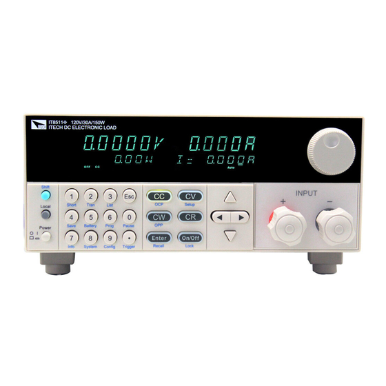
After selftest, VFD display information below. 0.0000V 0.0000A 0.00W CC=0.000A OFF CC Auto Information description: The first line display actual voltage and current value. The second line display the actual power value and the setting current/voltage/power/resistance value Copyright © Itech Electronics Co., Ltd. - Page 21 See the table blow for matching information of fuse and machine model. Fuse specification Fuse specification Model (220VAC) (110VAC) IT8511+ T0.5A 250V T1.25A 250V IT8511A+ T0.5A 250V T1.25A 250V IT8511B+ T0.5A 250V T1.25A 250V Copyright © Itech Electronics Co., Ltd.
- Page 22 IT8513C+ T1.25A 250V T2.5A 250V IT8514B+ T1.25A 250V T2.5A 250V IT8514C+ T1.25A 250V T2.5A 250V IT8516C+ T2.5A 250V T5A 250V After replacement, install the fuse box back to original position, as shown below. Copyright © Itech Electronics Co., Ltd.
-
Page 23: Chapter3 Functions And Characteristics
Constant voltage mode (CV) Constant resistance mode (CR) Constant power mode(CW) 3.2.1 Constant Current Mode (CC) In constant current mode, the DC load will comsume a constant current, regardless of the voltage at its terminals. Copyright © Itech Electronics Co., Ltd. -
Page 24: Constant Voltage Mode (Cv)
In constant power mode,the DC load will cause a constant power to be dissipated in the load.As shown below,the load current is decreasing with the rising of input voltage,while power always maintain the setting value. Copyright © Itech Electronics Co., Ltd. -
Page 25: Input On/Off Control
SAVE 0 to recall when power on POWER-ON the DC load next time. SAV0 Remember state in SAVE 0 BUZZER ON(default) Enable audible beep when key is pressed BUZZER No sound when key is pressed KNOB KNOB Copyright © Itech Electronics Co., Ltd. -
Page 26: Config Menu (Config)
Retrun instrument to factory default settings 3.6 Config Menu (Config) Press [ Shift ]+ [ 9 ] (Config) to enter the menus. Max-P Set hardware power protection PROTECT MAX POWER=150.00W Set hardware OPP value Copyright © Itech Electronics Co., Ltd. - Page 27 VON point living state VON POINT = 0.10V Set the VON value LATCH VON point latch state, ON /OFF VON POINT = 0.10V Set the VON value RESET Reset the config menu RESET Do not reset Reset Copyright © Itech Electronics Co., Ltd.
-
Page 28: Trigger Function
B value and stays at that level for the B timing value.Then the load switches back to the A value and stays there until another trigger is received. Copyright © Itech Electronics Co., Ltd. -
Page 29: Toggled Mode
3.10 Saving and Recalling Settings We can save some often-used parameters in the non volatile memory, including working mode, voltage/current value and so on.IT8500plus series provide 100 non-volatile registers. They are divided into 10 Memory groups: Group0-9.You can set it in the system menu.Group0 means you can save and recall parameters in 0-10 registers. -
Page 30: Von Function
In Living mode, when power is applied to the DC load, the voltage must rise above VON setting before the load draws current from the source.If the voltge below VON setting on the load’s terminals, the load will turn off input. Copyright © Itech Electronics Co., Ltd. -
Page 31: Ocp Operation
Save OCP test file (1-10) Set the power on mode to be OCP test mode: Operation Display on front pannel 1.Press [ Shift ]+ [ 8 ] (system) enter into sysmtem 0.0000V 0.000A POWER-ON BUZZER menu Copyright © Itech Electronics Co., Ltd. -
Page 32: Opp Operation
Display on front pannel 1.Press [ Shift ]+ [ 8 ] (system) enter into 0.0000V 0.000A POWER-ON BUZZER sysmtem menu 2.Press right key,select RUNMODE and 0.0000V 0.000A confirm with [ Enter ] button RUN <NORMAL Copyright © Itech Electronics Co., Ltd. -
Page 33: Battery Test
]. 3.14 Battery Test IT8500plus series products test the battery capability in CC/CW/CR mode. The test mode should be set first, and then the discharge stop conditions. There are three discharge stop conditions to be set for IT8500 plus series products. - Page 34 (7)Recall Battery File Press [ Shift ] + [ Enter ] button to select programe file,the panel displays “RECALL BATTERY 1.Enter the file name(1-10),press [ Enter ] button to Copyright © Itech Electronics Co., Ltd.
-
Page 35: Cr-Led Test Function
[Enter] key. Press [ ] to select “TimeV2”. Press [Enter] key. Press numeric keys to set final voltage value and press [Enter] key. Press [ESC] to exit setting. Start timer function Copyright © Itech Electronics Co., Ltd. -
Page 36: Protection Features
VFD displays OCP. Operations to clear the OCP state Disconnect the instrument under test. Press any key on the front panel, the displayed on the VFD will disappear, the DC load exits OCP protection state. Copyright © Itech Electronics Co., Ltd. -
Page 37: Over Power Protection (Opp)
When using remote sensing, the power displayed by the instrument includes both the power dissipated inside the instrument and the power dissipated in the Copyright © Itech Electronics Co., Ltd. -
Page 38: External Triggering
3.19.3 Current Monitoring (I Monitor) Current monitoring terminal will output 0-10V analog signal to corresponding to 0 to full range of input current. You can connect an external voltmeter or an oscilloscope to display the input current’s changing Copyright © Itech Electronics Co., Ltd. -
Page 39: 4Ripple Function
Functions and Characteristics 3.19.4Ripple Function IT8500plus series DC electronic loads have test ripple function.You can read ripple voltage and ripple current by sending instructions.See in IT8500+ programming guide. Copyright © Itech Electronics Co., Ltd. -
Page 40: Chapter4 Basic Operation
VFD Display [Shift] +[CV] RANGE=120.00V Press [CV], then voltage range, press RANGE=10.00V Enter] to confirm Press [Esc] to escape. HIGH=30.000A Note: When you set the voltage range to low range,the resolution of voltage will rise. Copyright © Itech Electronics Co., Ltd. -
Page 41: Constant Power Operation
(only in pulse mode), frequency, duty and running mode (Continuous/Pulse/Toggled). If in CC dynamic mode, user can set current rising and falling slope additionally. Following is an example to illustrate the three transient operations. Copyright © Itech Electronics Co., Ltd. -
Page 42: Continuous Transient Operation
Trig 0.00W TRAN. Trig Turn on the load, press [Shift]+[ (Trigger) to trigger Press anyone of [CC/CV/CW/CR] button can quit the transient test,if you want to continue the test again, please repeat 1-11 steps Copyright © Itech Electronics Co., Ltd. -
Page 43: Pulse Transient Operation
Turn on the load, press [Shift]+[ ] (Trigger) to trigger Press anyone of [CC/CV/CW/CR] button will quit the transient test,if you want to continue the test again,please repeat 1-10 steps. 4.5.3 Toggle Transient Operation Copyright © Itech Electronics Co., Ltd. -
Page 44: List Operation
Before run a list file,you should edit the list file firstly and save it in a non-volatile memory.The following examples will help you understand the function well.In the example, the output voltage and current are 10V and 3A,and the DC load is in CC mode. Copyright © Itech Electronics Co., Ltd. - Page 45 ] (Trigger) to trigger. Press any function ksys if you want to quit list mode If you want to run a list file you’ve saved, please recall it first.The steps is: Steps Operation VFD Display Copyright © Itech Electronics Co., Ltd.
-
Page 46: Test Files
Set Toff for the first step, if you SEQ01 OFF =2S want to load off 2S, press [2], then press [Enter] to confirm Toff range 0~60S Set testing delay time, range SEQ01 P/F =1S 0~60S e.g. 1S, press [1]. Copyright © Itech Electronics Co., Ltd. - Page 47 E-load.The unit can auto start to run test file when detect a rising edge from 0-2V.Auto start voltage is not suggested to be a big value.2V is suitable. Ton, Toff and Tpf (P/F) Relation: Copyright © Itech Electronics Co., Ltd.
- Page 48 [ to confirm Set the rise speed of current, UP=1A/uS Enter] press [ to confirm Set the fall speed of current, DOWN=1A/uS Enter] press [ to confirm Finish the setup 10.0000V 0.000A 0.00W CC=0.000A Copyright © Itech Electronics Co., Ltd.
- Page 49 Go into Autotest Mode Operation Display on Front Pannel 1.Press [Shift] (system) enter +[8] 0.0000V 0.000A into sysmtem menu POWER-ON BUZZER 2.Press right key,select 0.0000V 0.000A RUNMODE confirm with RUN <NORMAL [Enter] button Copyright © Itech Electronics Co., Ltd.
- Page 50 Press [Shift]+[Enter] button to select programe file,the panel displays “RECALL PROGRAM= 1.Enter the file name(1-10),press [Enter] button to confirm. If you need a pause, please press [Shift]+[0] (pause).Press [ ] can continue the test. Copyright © Itech Electronics Co., Ltd.
-
Page 51: Chapter5 Communication Interfaces
,so that can be directly connected to the standard LAN interface. IT-E121A communication cable IT-E122 Communication Module The DB9 interface connector on the rear panel of the DC load is TTL voltage level; Copyright © Itech Electronics Co., Ltd. -
Page 52: Communication With Pc
DC load are the same as in the computer software, otherwise, the communication will fail, you can change the baud rate and communication address from the front panel or from computer. Copyright © Itech Electronics Co., Ltd. - Page 53 CTS, clear to send RTS, request to send No conjunction Communication Setup Please ensure the PC and the load have the same configuration in the following items. Baudrate: 9600(4800、9600、19200、38400).You could enter the system menu Copyright © Itech Electronics Co., Ltd.
-
Page 54: Usb Interface
(each end). All functions of the load can be programmed via USB. After connecting the load and computer by USB, you need to install IT-E122 driver or IT-E132 driver ( see in ITECH CD or contact ITECH agent). The device manager of PC will display ‘Prolific USB-to-Serial COM Port’ after installing. -
Page 55: Chapter6 Specifications
150W 300W Readback resolution 10mW 10mW power accuracy ±(0.1%+0.1%FS) ±(0.1%+0.1%FS) Protection range ≒160W ≒320W Protection ≒3.3A ≒33A ≒3.3A ≒33A Protection ≒125V ≒125V Protection ≒85℃ ≒85℃ Protection Specification ≒3.3/3A ≒33/30A ≒3.3/3A ≒33/30A current(CC) Short voltage(CV) Copyright © Itech Electronics Co., Ltd. - Page 56 0.1mA 0.1mA current accuracy ±(0.05%+0.05%FS) ±(0.05%+0.05%FS) range 150W 300W Readbac resolution 10mW 10mW k power accuracy ±(0.1%+0.1%FS) ±(0.1%+0.1%FS) Protection range ≒320W ≒160W Protecti ≒3.3A ≒33A ≒3.3A ≒33A Protecti ≒160V ≒160V Protecti ≒85℃ ≒85℃ Protecti Copyright © Itech Electronics Co., Ltd.
- Page 57 ±(0.025%+0.025%FS) ±(0.025%+0.025%FS) range 0~3A 0~10A Readback resolution 0.1mA current accuracy ±(0.05%+0.05%FS) range 150W resolution 10mW Readback power accuracy ±(0.1%+0.2%FS) ≒160W Protection range OPP Protection ≒11A ≒3.3A OCP Protection ≒530V OVP Protection ≒85℃ OTP Protection Copyright © Itech Electronics Co., Ltd.
- Page 58 0~6A 0~60A Readback resolution 0.1mA 0.1mA current accuracy ±(0.05%+0.05%FS) ±(0.05%+0.05%FS) range 300W 300W Readback resolution 10mW 10mW power accuracy ±(0.1%+0.1%FS) ±(0.1%+0.1%FS) Protection range ≒320W ≒320W Protection ≒3.3A ≒16A ≒6.5A ≒65A Protection ≒530V ≒125V Protection Copyright © Itech Electronics Co., Ltd.
- Page 59 1 mV 10 mV voltage accuracy ±(0.025%+0.025%FS) ±(0.025%+0.025%FS) range 0~1A 0~5A Readback resolution 0.1mA current accuracy ±(0.05%+0.05%FS) range 300W Readback power resolution 10mW accuracy ±(0.2%+0.2%FS) Protection range ≒320W OPP Protection ≒1.1A ≒5.5A OCP Protection Copyright © Itech Electronics Co., Ltd.
- Page 60 Measuring range range 0~18V 0~150V Readback resolution 0.1 mV voltage accuracy ±(0.025%+0.025%FS) ±(0.025%+0.025%FS) range 0~6A 0~60A Readback resolution 0.1mA current accuracy ±(0.05%+0.05%FS) range 400W Readback resolution 10mW power accuracy ±(0.2%+0.2%FS) ≒420W Protection range Copyright © Itech Electronics Co., Ltd.
- Page 61 0~18V 0~120V 0~18V 0~120V Readback resolution 0.1 mV 0.1 mV voltage accuracy ±(0.025%+0.025%FS) range 0~12A 0~120A 0~24A 0~240A Readback resolution 10mA 10mA current accuracy ±(0.05%+0.05%FS) ±(0.05%+0.05%FS) range 600W 1500W Readback power resolution 10mW 10mW Copyright © Itech Electronics Co., Ltd.
- Page 62 0~120V Readback resolution 0.1 mV 0.1 mV voltage accuracy ±(0.025%+0.025%FS) range 0~6A 0~60A 0~24A 0~240A Readback resolution 10mA 10mA current accuracy ±(0.05%+0.05%FS) ±(0.1%+0.1%FS) range 1500W 3000W Readback resolution 10mW 10mW power accuracy ±(0.2%+0.2%FS) ±(0.2%+0.2%FS) Copyright © Itech Electronics Co., Ltd.
-
Page 63: Supplementary Characteristics
50Hz/60Hz Cooling type Intelligent fans Fans working principle: Fans running speed is determined by radiator temperature.When temperature reaches 40 ℃,fans start to work and intellig ently adjust its speed with temperature variation. Copyright © Itech Electronics Co., Ltd. -
Page 64: Appendix
Specifications of Red and Black Test Lines ITECH provides you with optional red and black test lines, which individual sales and you can select for test. For specifications of ITECH test lines and maximum current values, refer to the table below. - Page 65 Contact Us Thanks for purchasing ITECH products. In case of any doubts, please contact us as follows: 1. Refer to accompanying data disk and relevant manual. 2. Visit ITECH website: www.itechate.com. 3. Select the most convenient contact method for further information.
Need help?
Do you have a question about the IT8500plus Series and is the answer not in the manual?
Questions and answers