ITech IT8500+ Series Manual
Hide thumbs
Also See for IT8500+ Series:
- Programming manual (85 pages) ,
- User manual (80 pages) ,
- Manual (32 pages)

Related Manuals for ITech IT8500+ Series


Summary of Contents for ITech IT8500+ Series
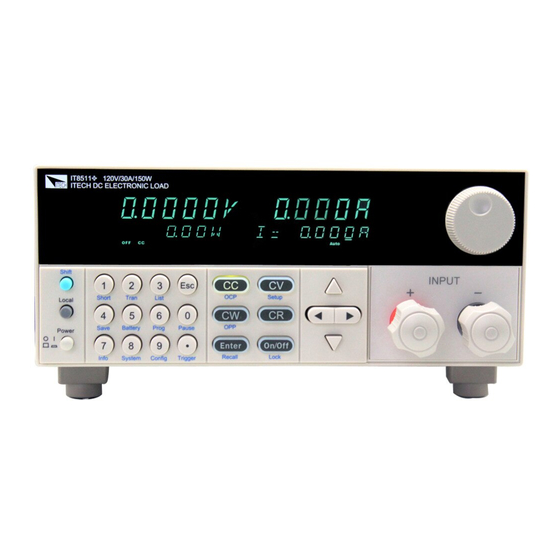
- Page 1 IT8500+ Series Frame Format Programmable DC Electronic Load Models IT8500+ © Copyright 2005 All Rights Reserved Ver1.1/MAR, 2008/8500-401...
- Page 2 Directory WARRANTY INFORMATION ........................3 SAFETY SUMMARY ..........................3 CHAPTER 1 REMOTE OPERATION MODE .................... 5 1.1 IT-E121 RS232 C ................5 OMMUNICATION CABLE 1.2 IT-E122 USB C ................5 OMMUNICATION CABLE CHAPTER 2 COMMUNICATION ORDER FOR IT8500+ ................. 5 ........................
- Page 3 Warranty Information Certification We certify that this product met its published specifications at time of shipment from the factory. Warranty This hardware product is warranted against defects in material and workmanship for a period of ONE year from date of delivery. IT8500 series electronic load for use with a hardware product and when properly installed on that hardware product, are warranted not to fail to execute their programming instructions due to defects in material and workmanship for a period of 90 days from date of delivery.
-
Page 4: Safety Symbols
Ground the Instrument This product is a Safety Class 1 instrument (provided with a protective earth terminal). To minimize shock hazard, the instrument chassis and cover must be connected to an electrical ground. The instrument must be connected to the ac power mains through a grounded power cable, with the ground wire firmly connected to an electrical ground (safety ground) at the power outlet. -
Page 5: Chapter 1 Remote Operation Mode
Chapter 1 Remote Operation Mode DB9 in the rear panel of electronic load could connect with RS-232 through a TTL connector. The following information may help you to know how to control the electronic load through PC. 1.1 IT-E121 RS232 Communication cable The DB9 interface connector on the rear panel of electronic load is TTL level.You can use the communication cable (IT-E121) to connect the DB9 interface with RS232 interface of PC. - Page 6 Enquire CC mode current value Set CV mode voltage value Enquire CV mode voltage value Set CW mode watt value Enquire CW mode watt value Set CR mode resistance value Enquire CR mode resistance value Set CC mode transient current and timer parameter. Enquire CC mode transient parameter Set CV mode transient voltage and timer parameter.
- Page 7 Enquire hardware OPP point Set software OCP point Enquire software OCP point Set OCP delay time Enquire OCP delay time Enable/disable OCP function Enquire the state of OCP function Set software OPP point Enquire software OPP point Set software OPP delay time Enquire software OPP delay time Set the first measuring point Enquire the first measuring point...
- Page 8 Enquire the voltage upper limit in CP mode Set the voltage lower limit in CP mode Enquire the voltage lower limit in CP mode Set the max input resistance Enquire the max input resistance Set the voltage upper limit in CR mode Enquire the voltage upper limit in CR mode Set the voltage lower limit in CR mode Enquire the voltage lower limit in CR mode...
-
Page 9: Communication Protocol
Communication Protocol 1. Set control mode(20H) byte Start bit ( AAH ) byte Address (0—31,0XFF) byte Command(20H) .byte Operation mode (0 is front panel operation mode , 1 is remote operation mode ) From 5 to 25 byte System reserve byte Sum code NOTE... - Page 10 4. Set / Read the max input current .(24H/25H) byte Start bit ( AAH ) byte Address(0—31,0XFF) byte Command(24H/25H) byte The Lowest byte of max current value byte The Lowest byte of max current value byte The higher byte of max current value byte The highest byte of max current value From 8...
- Page 11 From 5 to 25 byte System reserve byte Sum code 7. Set / Read current value of CC mode(2AH/2BH) byte Start bit ( AAH ) byte Address (0—31,0XFF) byte Command (2AH/2BH) byte The lowest byte of current value byte The lower byte of current value. byte The higher byte of current value.
- Page 12 byte Command(2EH/2FH) byte The lowest byte of max power value byte The lower byte of max power value byte The higher byte of max power value byte The highest byte of max power value to 25 byte System reserve byte Sum code NOTE Represent power by 4 bytes of Hex.
- Page 13 From 14 to 15 byte Time value of timer B (Lower bytes are in the front location, higher bytes are in the later location) (1 represent 0.1mS) byte Transition operation mode (0 is CONTINUES, 1 is PULSE, 2 is TOGGLED) From 17 to 25 byte...
- Page 14 byte Command(38H/39H) From 4 byte to 7 byte Setting value of resistance A (Lower bytes are in the front location, higher bytes are in the later location) From 8 byte to 9 byte. Time value of timer A (Lower bytes are in the front location, higher bytes are in the later location) (1 represents 0.1mS) From 10 byte to 13...
- Page 15 byte Address (0—31,0XFF) byte Command(40H/41H) From 4 byte to 5 byte Appointed one step From 6 to 9 byte Current value of current step (Lower bytes are in the front location, higher bytes are in the later location) From 10 to 11 byte Time value of current step (Lower bytes are in the front location, higher bytes are...
- Page 16 byte Command (54H) byte New communication address (0~31) From 5 to 25 byte System reserve byte Sum code 23. Enable/Disable LOCAL control mode. (55H) byte Start bit ( AAH ) byte Address (0—31) byte Command(55H) State of LOCAL button(0:disable,1:enable “) byte From 5 to 25...
- Page 17 byte Start bit ( AAH ) byte Address (0—31,0XFF) byte Command(5BH/5CH) byte Storing area From 5 to 25 byte System reserve byte Sum code 28. Selecting / Getting FIXED/SHORT/TRAN/LIST/ BATTERY function mode. (5DH/5EH) byte Start bit ( AAH ) byte Address (0—31,0XFF) byte Command(5DH/5EH)...
- Page 18 Reverse voltage Over voltage Over current Over power Over temperature remote sense wires are disconnected Constant current Constant voltage Constant power Constant resistance PASS Pass autotest FAULT fail to pass autotest COMPLET Complete autotest Get the information of E-Load(rated max current,max voltage,min voltage,max power,max resistance,min resistance).
- Page 19 Start bit ( AAH ) byte Address (0—31,0XFF) byte Command(80H/81H) byte OCP value From 4 to 7 byte Lower bytes are in the former location, higher bytes are in the later location System reserve From 8 to 25 byte byte Sum code 32.
- Page 20 Sum code byte 36. Set/Enquire the first measuring point.( 8AH/8BH) byte Start bit ( AAH ) Address (0—31,0XFF) byte byte Command(8AH/8BH) The first measuring value From 4 to 7 byte Lower bytes are in the former location, higher bytes are in the later location From 8 to 25 byte...
- Page 21 Auto voltage range state(0:off 1:on) From 4 System reserve From 5 to 25 byte byte Sum code 41. Enabel/Disable CR-LED function.( 93H/94H) byte Start bit ( AAH ) Address (0—31,0XFF) byte Command(93H/94H) byte CR-LED mode(0: OFF 1:ON) From 4 System reserve From 5 to 25 byte...
- Page 22 bytes are in the later location Max input current ( From 12 to 15 Lower bytes are in the former location, higher byte bytes are in the later location Min input current( From 16 to 19 Lower bytes are in the former location, higher bytes byte are in the later location System reserve...
- Page 23 ),reset this value after enquire higher bytes are in the later location Syetem reserve From 8 to 25 byte byte Sum code 49. Read on-load capacitance.( A6H) byte Start bit ( AAH ) Address (0—31,0XFF) byte Command(A6H) byte From 4 to 7 byte On-load capacitace (...
- Page 24 53. Set/Enquire the voltage lower limit in CC mode.( B6H/B7H) byte Start bit ( AAH ) Address (0—31,0XFF) byte byte Command(B6H/B7H) The voltaeg lower limit in CC mode ( From 4 to 7 byte Lower bytes are in the former location, higher bytes are in the later location From 8 to 25...
- Page 25 Command(BEH/BFH) byte The voltaeg lower limit ( From 4 to 7 byte Lower bytes are in the former location, higher bytes are in the later location Syetem reserve From 8 to 25 byte byte Sum code 58. Set/Read max input resistance setting of E-load.( C0H/C1H) Start bit ( AAH ) byte byte...
- Page 26 Sum code byte 62. Set/Enquire autotest steps.( D0H/D1H) byte Start bit ( AAH ) Address (0—31,0XFF) byte byte Command (D0H/D1H) Autotest steps From 4 to 5 byte Lower bytes are in the former location, higher bytes ),when one step is selected,then are in the later location corresponding bit should be set to 1.
- Page 27 Sum code byte 66. Set/Enquire delay time of single-step in autotest mode.(D8H/89H) byte Start bit ( AAH ) Address (0—31,0XFF) byte byte Command(D8H/D9H) byte Step number Single step delay time From 5 to 7 byte Lower bytes are in the former location, higher bytes are in the later location System reserve From 8...
- Page 28 Address (0—31,0XFF) byte Command(E0H/E1H) byte File number byte (0 repersents do not save) System reserve From 5 to 25 byte byte Sum code 71. Set/Enquire Von mode.(0EH/0FH) Start bit ( AAH ) byte byte Address (0—31,0XFF) Command(0EH/0FH) byte Von mode(0:Living 1:Latch) byte System reserve From 5...
- Page 29 2 Visit the ITECH online service Web site is www.itechate.com ,ITECH is available to all ITECH customers. It is the fastest source for up-to-date product information and expert assistance and includes the following features : Fast access to email AE...
Need help?
Do you have a question about the IT8500+ Series and is the answer not in the manual?
Questions and answers