Sign In
Upload
Download
Table of Contents
Contents
Add to my manuals
Delete from my manuals
Share
URL of this page:
HTML Link:
Bookmark this page
Add
Manual will be automatically added to "My Manuals"
Print this page
×
Bookmark added
×
Added to my manuals
Manuals
Brands
ITech Manuals
Test Equipment
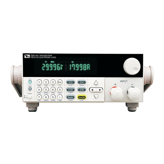
IT8511A
Manual
ITech IT8511A Manual
Programmable electronic load
Hide thumbs
1
2
3
4
5
6
7
8
9
10
11
12
13
14
15
16
17
18
19
20
21
22
23
24
25
26
27
28
29
30
31
32
33
34
35
36
37
38
39
40
41
42
43
44
45
46
47
48
49
50
51
52
53
54
55
56
57
58
59
60
61
62
63
64
65
66
67
68
69
page
of
69
Go
/
69
Contents
Table of Contents
Bookmarks
Table of Contents
Immediate Action Keys
Options and Accessories
Saving and Recalling Settings
Computer Connections
Turn-On Checkout
Checkout Procedure
Front Panel Operation
Function Keys
Entry Keys
Menu Description
Continuous Transient Operation
Pulse Transient Operation
Toggled Transient Operation
List Operation
Specifications
Remote Operation Mode
Communication Setting
Communication Protocol
Advertisement
Quick Links
1
Immediate Action Keys
2
Remote Operation Mode
Download this manual
사용자 가이드
DC 전자로드
모델: IT 8511, IT 8512
© 저작권 2004 판권 소유
Ver1.0 /FEB, 2004/ IT8500-603
1
Table of
Contents
Previous
Page
Next
Page
1
2
3
4
5
Advertisement
Table of Contents
Need help?
Do you have a question about the IT8511A and is the answer not in the manual?
Ask a question
Questions and answers
Related Manuals for ITech IT8511A
Test Equipment ITech IT8500plus Series User Manual
Dc programmable electronic loads (65 pages)
Test Equipment ITech IT8500plus Series User Manual
Dc programmable electronic load (56 pages)
Test Equipment ITech IT8500+ Series Programming Manual
Dc programmable electronic load (85 pages)
Test Equipment ITech IT8300 Series Programming Manual
Energy-regenerative dc electronic load (100 pages)
Test Equipment ITech IT8817 User Manual
Dc programmable electronic load (44 pages)
Test Equipment ITech IT8800 Series User Manual
Programmable dc electronic load (92 pages)
Test Equipment ITech IT8800 Series User Manual
Programmable dc electronic load (53 pages)
Test Equipment ITech IT8800 User Manual
Dc programmal electronic load (65 pages)
Test Equipment ITech IT8700 Series Programming Manual
Dc programmable electronic loads (133 pages)
Test Equipment ITech IT8000 Series User Manual
Regenerative dc electronic load (136 pages)
Test Equipment ITech IT8600 Series Manual
Programmable ac/dc electronic load (78 pages)
Test Equipment ITech IT8600 Series Programming Manual
Programmable ac/dc electronic load (77 pages)
Test Equipment ITech IT8211 User Manual
Digital control electronic load (16 pages)
Test Equipment ITech IT8512A Manual
Programmable electronic load (69 pages)
Test Equipment ITech IT5101 User Manual
Internal resistance testet (53 pages)
Test Equipment ITech IT5101 Programming Manual
Internal resistance tester (48 pages)
This manual is also suitable for:
It8512a
Table of Contents
Print
Rename the bookmark
Delete bookmark?
Delete from my manuals?
Login
Sign In
OR
Sign in with Facebook
Sign in with Google
Upload manual
Upload from disk
Upload from URL


Need help?
Do you have a question about the IT8511A and is the answer not in the manual?
Questions and answers