
Related Manuals for Danfoss VACON 100 INDUSTRIAL


Summary of Contents for Danfoss VACON 100 INDUSTRIAL
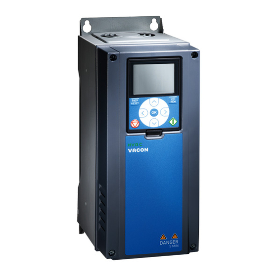
- Page 1 Operating Guide VACON® 100 Wall-mounted Drives VACON® 100 INDUSTRIAL, VACON® 100 FLOW, VACON® 100 HVAC...
-
Page 3: Table Of Contents
Using the Product Modified Label 5 Mounting Wall-mounting Requirements Flange-mounting Requirements Cooling Requirements 5.3.1 General Cooling Requirements 5.3.2 Cooling 5.3.3 Necessary Quantity of Cooling Air 6 Electrical Installation Cable Connections 6.1.1 General Cable Requirements Danfoss A/S © 2019.05 AQ298036140958en-000101 / | 3... - Page 4 General Cabling Instructions for Fieldbus 7.4.3.1 Cable Routing 7.4.3.2 Strain Relief 7.4.4 Ethernet Commissioning and Cabling 7.4.4.1 General Cabling Instructions for Ethernet 7.4.4.2 Grounding the Cable Shield 7.4.4.3 Using Fieldbus through an Ethernet Cable 4 | Danfoss A/S © 2019.05 AQ298036140958en-000101 /...
- Page 5 10.2.2.3 Dimensions for Flange-mounting for MR6 10.2.2.4 Dimensions for Flange-mounting for MR7 10.3 Cable and Fuse Sizes 10.3.1 List of Cable and Fuse Size Information 10.3.2 Cable and Fuse Sizes, Mains Voltage 208–240 V and 380–500 V Danfoss A/S © 2019.05 AQ298036140958en-000101 / | 5...
- Page 6 Brake Resistance and Brake Power, Mains Voltage 525–600 V 10.8.8 Brake Resistance and Brake Power, Mains Voltage 525–690 V 10.9 Control Connections 10.10 Technical Data, VACON® 100 INDUSTRIAL 10.11 Technical Data, VACON® 100 FLOW 10.12 Technical Data, VACON® 100 HVAC 6 | Danfoss A/S © 2019.05 AQ298036140958en-000101 /...
-
Page 7: Introduction
Do not dispose of equipment containing electrical components together with domestic waste. Collect it separately in accordance with local and currently valid legislation. 1.3 Type Approvals and Certifications The following list is a selection of possible type approvals and certifications for Danfoss drives: Danfoss A/S © 2019.05 AQ298036140958en-000101 / DPD01711| 7... - Page 8 N O T I C E The specific approvals and certification for the drive are on the nameplate of the drive. For more information, contact the local Danfoss office or partner. 8 | Danfoss A/S © 2019.05 AQ298036140958en-000101 / DPD01711...
-
Page 9: Safety
Do not touch the motor terminals U, V, W, the brake resistor terminals, or the DC terminals when the drive is connected to mains. Before connecting the drive to mains, make sure that the covers of the drive are closed. Danfoss A/S © 2019.05 AQ298036140958en-000101 / DPD01711| 9... - Page 10 (RCM) device can lead to the RCD not providing the intended protection and therefore can result in death or serious injury. Use a type B RCD or RCM device on the mains side of the drive. 10 | Danfoss A/S © 2019.05 AQ298036140958en-000101 / DPD01711...
-
Page 11: Cautions And Notices
Some of the electronic components inside the AC drive are sensitive to ESD. Static voltage can damage the components. Remember to use ESD protection always when working with electronic components of the AC drive. Do not touch the components on the circuit boards without proper ESD protection. Danfoss A/S © 2019.05 AQ298036140958en-000101 / DPD01711| 11... - Page 12 N O T I C E VOLTAGE WITHSTAND TESTS Doing voltage withstand tests can damage the drive. Do not do voltage withstand tests on the AC drive. The manufacturer has already done the tests. 12 | Danfoss A/S © 2019.05 AQ298036140958en-000101 / DPD01711...
-
Page 13: Product Overview
100 IP00 drive modules was removed. Hyperlink to company web page was updated. Structure of the manual was changed. Minor changes throughout the manual. 3.2 Package Label The package label gives detailed information about the delivery. Danfoss A/S © 2019.05 AQ298036140958en-000101 / DPD01711| 13... -
Page 14: Description Of The Type Code
3.3 Description of the Type Code ® The type code of VACON is made of standard codes and optional codes. Each part of the type code agrees to the data in the order. 14 | Danfoss A/S © 2019.05 AQ298036140958en-000101 / DPD01711... -
Page 15: Enclosure Sizes
Label). Use these values to find out the enclosure size of the AC drive from the table. In the example "VACON0100-3L-0061-5+IP54", the code for nominal current is 0003 and the code for nominal mains voltage is 5. Danfoss A/S © 2019.05 AQ298036140958en-000101 / DPD01711| 15... - Page 16 Table 3: Enclosure Sizes Nominal mains voltage Nominal current Enclosure size 2 (208–240 V) 0003 0004 0007 0008 0011 0012 0018 0024 0031 0048 0062 0075 0088 0105 0140 0170 0205 0261 MR9A 0310 16 | Danfoss A/S © 2019.05 AQ298036140958en-000101 / DPD01711...
- Page 17 Nominal mains voltage Nominal current Enclosure size 5 (380–500 V) 0003 0004 0005 0008 0009 0012 0016 0023 0031 0038 0046 0061 0072 0087 0105 0140 0170 0205 0261 MR9A 0310 0386 MR9B Danfoss A/S © 2019.05 AQ298036140958en-000101 / DPD01711| 17...
- Page 18 0062 0080 0100 0125 0144 MR9A 0208 0262 MR9B 7 (525–690 V) 0007 0010 0013 0018 0022 0027 0034 0041 0052 0062 0080 0100 0125 0144 MR9A 0170 0208 0262 MR9B 18 | Danfoss A/S © 2019.05 AQ298036140958en-000101 / DPD01711...
-
Page 19: Receiving The Delivery
M4x16 screw Screws for the grounding clamps for cable shield (6), the grounding clamps for control cable (3), and the grounding clamps for grounding conductor (4) M4x8 screw Screw for the optional grounding Danfoss A/S © 2019.05 AQ298036140958en-000101 / DPD01711| 19... -
Page 20: Accessories Bag, Mr6
Nuts for the grounding clamps for cable shield M4x16 screw Screws for the grounding clamps for control cable M6x12 screw Screw for the external grounding of the drive Grounding clamp for control cable Control cable grounding 20 | Danfoss A/S © 2019.05 AQ298036140958en-000101 / DPD01711... -
Page 21: Accessories Bag, Mr8
Cable grommet, hole diameter 25.3 mm Sealing for the cables Bushing rubber Sealing for the control cables M4x8 screw For installation M8 hexagon nut For installation Split spring washer For grounding clamp installation Danfoss A/S © 2019.05 AQ298036140958en-000101 / DPD01711| 21... -
Page 22: Storing The Product
Not following the safe lifting instructions can result in death or serious injury. Do not walk under suspended loads. Use lifting devices that are appropriate for the weight of the unit. Use the recommended lifting method. 22 | Danfoss A/S © 2019.05 AQ298036140958en-000101 / DPD01711... -
Page 23: Using The Product Modified Label
In the accessories bag, there is also a "product modified" label. The function of the label is to tell the service personnel about the changes that are made in the AC drive. Danfoss A/S © 2019.05 AQ298036140958en-000101 / DPD01711| 23... - Page 24 1. Attach the label on the side of the AC drive to know where to find it. 2. If changes are made in the AC drive, write the change on the label. 24 | Danfoss A/S © 2019.05 AQ298036140958en-000101 / DPD01711...
-
Page 25: Mounting
The protection classes are different in different sections of the drive. A The cabinet wall or other surface B The front C The rear D IP21/UL Type 1 E IP54/UL Type 12 Illustration 4: Example of Flange Mounting Danfoss A/S © 2019.05 AQ298036140958en-000101 / DPD01711| 25... - Page 26 Table 11: The Dimensions of the Opening for the Flange Mounting, MR4 to MR7, in mm (in inch) Enclosure size 315 (12.4) 137 (5.4) 24 (0.9) 408 (16.1) 152 (6.0) 23 (0.9) 541 (21.3) 203 (8.0) 23 (0.9) 655 (25.8) 240 (9.4) 13 (0.5) 26 | Danfoss A/S © 2019.05 AQ298036140958en-000101 / DPD01711...
-
Page 27: Cooling Requirements
B The distance from a drive to a second drive, or the distance to the cabinet wall C The free space above the drive D The free space below the drive Illustration 6: Installation Space Danfoss A/S © 2019.05 AQ298036140958en-000101 / DPD01711| 27... - Page 28 20 (0.8) 300 (11.8) 150 (5.9) 20 (0.8) 20 (0.8) 350 (13.8) 200 (7.9) For a drive with IP54/UL Type 12, the minimum clearances A and B are 0 mm/0 in. 28 | Danfoss A/S © 2019.05 AQ298036140958en-000101 / DPD01711...
- Page 29 Make also sure that the outlet air from the lower drive goes to a different direction than the air intake of the top drive. To do this, attach a metal plate to the cabinet wall between the drives. • When the drives are installed in a cabinet, make sure to prevent recirculation of air. Danfoss A/S © 2019.05 AQ298036140958en-000101 / DPD01711| 29...
-
Page 30: Necessary Quantity Of Cooling Air
Operating Guide | VACON® 100 Wall-mounted Drives Mounting 5.3.3 Necessary Quantity of Cooling Air Table 13: The Necessary Quantity of Cooling Air Enclosure size The quantity of cooling air, CFM The quantity of cooling air, m 30 | Danfoss A/S © 2019.05 AQ298036140958en-000101 / DPD01711... -
Page 31: Electrical Installation
These instructions are valid only for processes that have 1 motor and 1 cable connection from the AC drive to the motor. In other conditions, speak to the manufacturer to get more information. Danfoss A/S © 2019.05 AQ298036140958en-000101 / DPD01711| 31... -
Page 32: Ul Standards On Cabling
When using parallel cables, make sure to obey the requirements of the cross-sectional area and the maximum number of cables. For important information on the requirements of the grounding conductor, see the Underwriters Laboratories standard UL 61800-5-1. 32 | Danfoss A/S © 2019.05 AQ298036140958en-000101 / DPD01711... -
Page 33: Fuse Selection
MR6 have the brake chopper as standard. N O T I C E ® The VACON 100 FLOW and HVAC software do not have the dynamic braking or the brake resistor functions. Danfoss A/S © 2019.05 AQ298036140958en-000101 / DPD01711| 33... -
Page 34: Emc-Compliant Installation
For the definitions of EMC protection levels, see IEC/EN 61800-3 + A1. A The PE conductor and the shield B The PE conductors C The shield Illustration 9: Cables with PE Conductors 34 | Danfoss A/S © 2019.05 AQ298036140958en-000101 / DPD01711... -
Page 35: Installation In A Corner-Grounded Network
There must be an automatic disconnection of the mains, if the protective earthing conductor breaks. OR • There must be a terminal for a second protective earthing conductor in the same cross-sectional area as the first protective earthing conductor. Danfoss A/S © 2019.05 AQ298036140958en-000101 / DPD01711| 35... -
Page 36: Get Access And Locate The Terminals
6.4 Get Access and Locate the Terminals 6.4.1 Get Access and Locate the Terminals for MR4-MR7 Context: Follow these instructions to open the AC drive for installing the cables, for example. 36 | Danfoss A/S © 2019.05 AQ298036140958en-000101 / DPD01711... - Page 37 1. Open the cover of the AC drive. M4x55 2. Remove the screws of the cable cover. Remove the cable cover. Do not open the cover of the power unit. M4x8 3. Locate the terminals. Danfoss A/S © 2019.05 AQ298036140958en-000101 / DPD01711| 37...
-
Page 38: Get Access And Locate The Terminals For Mr8
C Motor terminals Illustration 10: Locating the Terminals, MR4-MR7 6.4.2 Get Access and Locate the Terminals for MR8 Context: Follow these instructions to open the AC drive for installing the cables, for example. 38 | Danfoss A/S © 2019.05 AQ298036140958en-000101 / DPD01711... - Page 39 Operating Guide | VACON® 100 Wall-mounted Drives Electrical Installation Procedure 1. Open the cover of the AC drive. 2. Remove the cable cover. M4x8 3. Remove the cable entry plate. M4x8 4. Remove the EMC shield plate. Danfoss A/S © 2019.05 AQ298036140958en-000101 / DPD01711| 39...
-
Page 40: Get Access And Locate The Terminals For Mr9
5. Find the motor terminals. The location of the terminals is different than usually, especially in MR8. R+ R- L2 L3 DC- 6.4.3 Get Access and Locate the Terminals for MR9 Context: Follow these instructions to open the AC drive for installing the cables, for example. 40 | Danfoss A/S © 2019.05 AQ298036140958en-000101 / DPD01711... - Page 41 Operating Guide | VACON® 100 Wall-mounted Drives Electrical Installation Procedure 1. Open the cover of the AC drive. M4x10 2. Remove the cable cover. M4x8 3. Remove the cable entry plate. Danfoss A/S © 2019.05 AQ298036140958en-000101 / DPD01711| 41...
- Page 42 Operating Guide | VACON® 100 Wall-mounted Drives Electrical Installation M5x10 4. Loosen the screws and remove the sealing plate. M4x8 5. Remove the EMC shield plate. 42 | Danfoss A/S © 2019.05 AQ298036140958en-000101 / DPD01711...
-
Page 43: Installation Of Cables
The distance between ca- The length of the shielded cable The distance between ca- The length of the shielded cable bles [m] bles [ft] [ft] ≤ 50 ≤ 164.0 ≤ 300 ≤ 656.1 Danfoss A/S © 2019.05 AQ298036140958en-000101 / DPD01711| 43... -
Page 44: Installing The Cables, Mr4-Mr7
Make sure that the delivery contains all necessary components. For the installation, the contents of the accessories bag is needed, see Accessories. Open the covers according to instructions in 6.4.1 Get Access and Locate the Terminals for MR4-MR7. 44 | Danfoss A/S © 2019.05 AQ298036140958en-000101 / DPD01711... - Page 45 If this is not possible, make the connection tight with some insulation tape or a cable tie. 6. Remove the grounding clamps for cable shield and the grounding clamps for grounding conductor. The tightening torque is 2.2 Nm or 19.5 lb-in. Danfoss A/S © 2019.05 AQ298036140958en-000101 / DPD01711| 45...
- Page 46 C Attach the grounding conductor of each cable to a grounding terminal with a grounding clamp for grounding conductor. D Make sure that the external grounding conductor is connected to the grounding bar. See Grounding. 46 | Danfoss A/S © 2019.05 AQ298036140958en-000101 / DPD01711...
- Page 47 B If a double grounding is necessary, use the grounding terminal under the drive. Use an M5 screw and tighten it to 2.0 Nm or 17.7 lb-in. = M5; 2 Nm 10. Attach again the cable cover. Danfoss A/S © 2019.05 AQ298036140958en-000101 / DPD01711| 47...
-
Page 48: Installing The Cables, Mr8-Mr9
Make sure that the delivery contains all necessary components. For the installation, the contents of the accessories bag is needed, see Accessories. Open the covers according to instructions in 6.4.2 Get Access and Locate the Terminals for MR8 6.4.3 Get Access and Locate the Terminals for MR9. 48 | Danfoss A/S © 2019.05 AQ298036140958en-000101 / DPD01711... - Page 49 A With the protection rating IP54 (UL Type 12), the connection between the grommet and the cable must be tight. Pull the first bit of the cable out of the grommet so that it stays straight. B If this is not possible, make the connection tight with some insulation tape or a cable tie. Danfoss A/S © 2019.05 AQ298036140958en-000101 / DPD01711| 49...
- Page 50 B Attach the grounding conductor of each cable to a grounding terminal with a grounding clamp for grounding conductor. C Make sure that the external grounding conductor is connected to the grounding bar. See Grounding. 50 | Danfoss A/S © 2019.05 AQ298036140958en-000101 / DPD01711...
- Page 51 Connecting the Cables, MR8 A The grounding connection Illustration 15: Connecting the Cables, MR9 6. If many cables are used on one connector, put the cable lugs on top of each other. Danfoss A/S © 2019.05 AQ298036140958en-000101 / DPD01711| 51...
- Page 52 A To comply with the requirements of the standard EN 61800-5-1, obey the instructions in Grounding. B Connect the protective conductor to one of the screw connectors with a cable shoe and an M8 screw. 52 | Danfoss A/S © 2019.05 AQ298036140958en-000101 / DPD01711...
-
Page 53: Installation In An It System
Use these instructions to change the EMC protection of the AC drive to level C4. Prerequisites: Open the cover of the AC drive (for MR4-MR6) and remove the cable cover (for MR4-MR5) as instructed in 6.4.1 Get Access and Locate the Terminals for MR4-MR7. Danfoss A/S © 2019.05 AQ298036140958en-000101 / DPD01711| 53... - Page 54 1. Find the EMC jumpers that connect the RFI filters to ground. MR6, 200–500 V MR6, 600/690 V 2. To disconnect the RFI filters from ground, remove the EMC jumpers. Pull the EMC jumper out with the tool. 54 | Danfoss A/S © 2019.05 AQ298036140958en-000101 / DPD01711...
-
Page 55: Installing The Ac Drive In An It System, Mr7
Use these instructions to change the EMC protection of the AC drive to level C4. Prerequisites: Open the cover of the AC drive and remove the cable cover (for 600/690 V) as instructed in 6.4.1 Get Access and Locate the Terminals MR4-MR7. Danfoss A/S © 2019.05 AQ298036140958en-000101 / DPD01711| 55... - Page 56 2. Remove the EMC jumper. Attach the cover of the EMC box again. 3. Find the DC grounding busbar between the terminals R- and U. To remove the busbar from the frame, remove the M4 screw. 56 | Danfoss A/S © 2019.05 AQ298036140958en-000101 / DPD01711...
- Page 57 4. After the change, write "The EMC level was changed" and the date on the "product modified" label. If the label is not yet attached, attach it on the drive near the nameplate. Product modified Date: Date: Date: Danfoss A/S © 2019.05 AQ298036140958en-000101 / DPD01711| 57...
-
Page 58: Installing The Ac Drive In An It System, Mr8
Use these instructions to change the EMC protection of the AC drive to level C4. Prerequisites: Open the cover of the AC drive and remove the cable cover as instructed in 6.4.2 Get Access and Locate the Terminals for MR8. 58 | Danfoss A/S © 2019.05 AQ298036140958en-000101 / DPD01711... - Page 59 6. After the change, write "The EMC level was changed" and the date on the "product modified" label. If the label is not yet attached, attach it on the drive near the nameplate. Danfoss A/S © 2019.05 AQ298036140958en-000101 / DPD01711| 59...
-
Page 60: Installing The Ac Drive In An It System, Mr9
Use these instructions to change the EMC protection of the AC drive to level C4. Prerequisites: Open the cover of the AC drive as instructed in 6.4.3 Get Access and Locate the Terminals for MR9. 60 | Danfoss A/S © 2019.05 AQ298036140958en-000101 / DPD01711... - Page 61 8. After the change, write "The EMC level was changed" and the date on the "product modified" label. If the label is not yet attached, attach it on the drive near the nameplate. Product modified Date: Date: Date: Danfoss A/S © 2019.05 AQ298036140958en-000101 / DPD01711| 61...
- Page 62 2. After the change, write "The EMC level was changed" and the date on the "product modified" label. If the label is not yet attached, attach it on the drive near the nameplate. Product modified Date: Date: Date: 62 | Danfoss A/S © 2019.05 AQ298036140958en-000101 / DPD01711...
-
Page 63: Installation In A Marine Environment
Product modified Date: Date: Date: 6.7 Installation in a Marine Environment When you install the AC drive in a marine environment, see the Marine Installation Guide. Danfoss A/S © 2019.05 AQ298036140958en-000101 / DPD01711| 63... -
Page 64: Control Unit
K A fan (only in IP54 of MR4 and of MR5) M The location and the default position of the Safe Torque Off (STO) jumper Illustration 19: Components of the Control Unit 64 | Danfoss A/S © 2019.05 AQ298036140958en-000101 / DPD01711... -
Page 65: Control Unit Cabling
8 relay board terminals. Some terminals are assigned for signals that have optional functions that can be used with the DIP switches. For more information, see 7.3 DIP Switches on the Control Unit. Danfoss A/S © 2019.05 AQ298036140958en-000101 / DPD01711| 65... - Page 66 RO2 CM FAULT RO2 NO RO3 CM Relay output 3 READY RO3 NO Illustration 20: The Signals of the Control Terminals on the Default I/O Board and the Default Control Connections 66 | Danfoss A/S © 2019.05 AQ298036140958en-000101 / DPD01711...
-
Page 67: Dip Switches On The Control Unit
Two selections for specified terminals can be done with the DIP switches. The switches have two positions: up and down. See the location of the DIP switches and the possible selections in illustration Danfoss A/S © 2019.05 AQ298036140958en-000101 / DPD01711| 67... - Page 68 E The RS485 bus termination Illustration 23: The Selections of the DIP Switches Table 18: The Default Positions of the DIP Switches The DIP switch The default position RS485 bus termination 68 | Danfoss A/S © 2019.05 AQ298036140958en-000101 / DPD01711...
-
Page 69: Isolation Of The Digital Inputs From Ground
• If an RS485 cable is used, connect it to terminals A and B of the standard I/O board. • If an Ethernet cable is used, connect it to the Ethernet terminal. Danfoss A/S © 2019.05 AQ298036140958en-000101 / DPD01711| 69... -
Page 70: Internal Fieldbuses In Vacon® 100 Products
LED is dimmed (dark) when the port is connected to a 1000 Mbit/s network. The AC drive does not support a 1000 Mbit/s Ethernet, so there is no communication. ® The VACON 100 product family supports internally three RS485 fieldbuses: 70 | Danfoss A/S © 2019.05 AQ298036140958en-000101 / DPD01711... -
Page 71: General Cabling Instructions For Fieldbus
Use cables with right length. If there is extra cable, put it in a noise free location. Multiple rounds of cable and a large circumstance area make an antenna (see illustration 27). Noise connects to fieldbus cable and can cause communication problems. Danfoss A/S © 2019.05 AQ298036140958en-000101 / DPD01711| 71... - Page 72 Example of Good Routing of Extra Fieldbus Cable N O T I C E To prevent shield fracture, do not bend the cable too much or run the cable back and forth on the same path. 72 | Danfoss A/S © 2019.05 AQ298036140958en-000101 / DPD01711...
-
Page 73: Strain Relief
29). This grounds the disturbances and, to some degree, prevents current from flowing in the cable shield. To do this, use shielded Ethernet cable (S/FTP or STP) which grounds devices via a RJ45 connector and thus uses a built-in drive RC circuit. Danfoss A/S © 2019.05 AQ298036140958en-000101 / DPD01711| 73... - Page 74 We recommend grounding the cable shield as in examples A and C (see illustration 32). Do not ground the cable shield as in example A Cable clamp B Ground terminal C Cable gland Illustration 32: Grounding the Cable Shield 74 | Danfoss A/S © 2019.05 AQ298036140958en-000101 / DPD01711...
-
Page 75: Using Fieldbus Through An Ethernet Cable
Open the covers according to instructions in 6.4.1 Get Access and Locate the Terminals for MR4-MR7, 6.4.2 Get Access and Locate the Terminals for MR8, or 6.4.3 Get Access and Locate the Terminals for MR9. Danfoss A/S © 2019.05 AQ298036140958en-000101 / DPD01711| 75... -
Page 76: Danfoss A/S © 2019.05 Aq298036140958En
2. In IP21, cut free the opening on the cover of the AC drive for the Ethernet cable. 3. In IP54, cut a hole in a grommet and move the cable through it. 76 | Danfoss A/S © 2019.05 AQ298036140958en-000101 / DPD01711... - Page 77 4. Put the cover of the drive back. Pull the fieldbus cables away from other cables. A Ethernet cable Illustration 34: Routing the Ethernet Cables in IP21 Danfoss A/S © 2019.05 AQ298036140958en-000101 / DPD01711| 77...
-
Page 78: Rs485 Commissioning And Cabling
Table 20: The RS485 Cable Lengths Baud rate (kbit/s) Length of line A (m) Length of line B (m) 1200 1200 19.2 1200 1200 93.75 1200 1200 187.5 1000 1500 3000–12000 78 | Danfoss A/S © 2019.05 AQ298036140958en-000101 / DPD01711... -
Page 79: Grounding The Cable Shield
Grounding in Noisy Environment with Poor Equipotential. An Example of Cutting the Shield. We recommend grounding the cable shield as in examples A and C (see illustration 38). Do not ground the cable shield as in example Danfoss A/S © 2019.05 AQ298036140958en-000101 / DPD01711| 79... -
Page 80: The Rs485 Bus Biasing
Open the covers according to instructions in 6.4.1 Get Access and Locate the Terminals for MR4-MR7, 6.4.2 Get Access and Locate the Terminals for MR8, or 6.4.3 Get Access and Locate the Terminals for MR9. 80 | Danfoss A/S © 2019.05 AQ298036140958en-000101 / DPD01711... - Page 81 A = negative • B = positive 3. Attach the shield of the cable to the frame of the drive with a grounding clamp for the control cable to make a grounding connection. Danfoss A/S © 2019.05 AQ298036140958en-000101 / DPD01711| 81...
- Page 82 The termination resistors are placed at both ends of the fieldbus line to decrease signal reflections on the line. Biasing is built in the bus termination resistor. The termination resistance is 220 Ω. 82 | Danfoss A/S © 2019.05 AQ298036140958en-000101 / DPD01711...
- Page 83 6. Put the cover of the drive back. Pull the RS485 cables to the side. A Keep the distance of the Ethernet, I/O and Fieldbus cables from the motor cable at a minimum of 30 cm (11.81 in). Danfoss A/S © 2019.05 AQ298036140958en-000101 / DPD01711| 83...
-
Page 84: Available Option Boards
C, D, E OPTBH The Temperature measurement board C, D, E OPTBJ The Safe Torque Off board OPTC4 The LonWorks fieldbus board D, E OPTE2 The RS485 (Modbus/N2) fieldbus board D, E 84 | Danfoss A/S © 2019.05 AQ298036140958en-000101 / DPD01711... -
Page 85: Option Board Installation
If the installed board is an OPTB or an OPTC option board, make sure that the label on it says "dv" (dual voltage). This marking shows that the option board is compatible with the drive. Danfoss A/S © 2019.05 AQ298036140958en-000101 / DPD01711| 85... - Page 86 The option board has a slot coding, because of which it is not possible to install the option board in an incorrect slot. A The slot coding B The option slots Illustration 43: Installing the Option Boards 3. Close the cover of the control unit. 86 | Danfoss A/S © 2019.05 AQ298036140958en-000101 / DPD01711...
-
Page 87: Battery For The Real-Time Clock (Rtc)
The digital inputs on the standard I/O board can be galvanically isolated from the I/O ground. To isolate the digital inputs, use the DIP switch that has the positions FLOAT and GND. See 7.3.2 Isolation of the Digital Inputs from Ground. Danfoss A/S © 2019.05 AQ298036140958en-000101 / DPD01711| 87... -
Page 88: Description Of The Control Panel
The control panel is the interface between the AC drive and the user. With the control panel, you can control the speed of a motor and monitor the status of the AC drive. You can also set the parameters of the AC drive. 88 | Danfoss A/S © 2019.05 AQ298036140958en-000101 / DPD01711... -
Page 89: Displays Of The Control Panel
Your location in the menu structure. If the text in the text display is too long for the display, the text scrolls to show the full text string. Some functions are only available in the graphical display. Danfoss A/S © 2019.05 AQ298036140958en-000101 / DPD01711| 89... - Page 90 F The indicators of the rotation direction Illustration 47: Text Display of the Control Panel ® ® ® See more information in the VACON 100 INDUSTRIAL, VACON 100 FLOW, and VACON 100 HVAC Application Guides. 90 | Danfoss A/S © 2019.05 AQ298036140958en-000101 / DPD01711...
-
Page 91: Commissioning
The control terminals can have a dangerous voltage also when the drive is disconnected from mains. A contact with this voltage can lead to injury. Make sure that there is no voltage in the control terminals before touching the control terminals. Danfoss A/S © 2019.05 AQ298036140958en-000101 / DPD01711| 91... -
Page 92: Commissioning The Ac Drive
8.3.1 Insulation Checks of the Motor Cable • The insulation checks of the mains cable, see 8.3.2 Insulation Checks of the Mains Cable • The insulation checks of the motor, see 8.3.3 Insulation Checks of the Motor 92 | Danfoss A/S © 2019.05 AQ298036140958en-000101 / DPD01711... -
Page 93: Insulation Checks Of The Motor Cable
5. Connect the motor cables to the motor. 6. Do the final insulation check on the drive side. Put all phases together and measure to the ground. 7. Connect the motor cables to the drive. Danfoss A/S © 2019.05 AQ298036140958en-000101 / DPD01711| 93... -
Page 94: Checking The Ac Drive After Commissioning
3. Activate the Start-up wizard. See the relevant application guide. 4. Set the maximum frequency reference (that is, the maximum speed of the motor) to agree with the motor and the device that is connected to the motor. 94 | Danfoss A/S © 2019.05 AQ298036140958en-000101 / DPD01711... -
Page 95: Maintenance
Clean the heat sink and the cooling channel. ent environments.) 3–6 years In IP54, change the internal fan. 6–10 years Change the main fan. 10 years Replace the battery of the RTC. Danfoss A/S © 2019.05 AQ298036140958en-000101 / DPD01711| 95... -
Page 96: Specifications
10.2.1.1 Dimensions for Wall-mounting for MR4 128 (5.04) 190 (7.48) Ø7 (0.28) IP21 100 (3.94) Ø13 (0.51) Ø25 (0.98) IP54 Ø25 (0.98) 100 (3.94) Illustration 48: Dimensions of the AC Drive, MR4, mm (in) 96 | Danfoss A/S © 2019.05 AQ298036140958en-000101 / DPD01711... -
Page 97: Dimensions For Wall-Mounting For Mr5
100 (3.94) 115 (4.53) A Mounting holes for replacing a VACON ® ® NX AC drive with a VACON 100 Wall-mounted AC drive Illustration 49: Dimensions of the AC Drive, MR5, mm (in) Danfoss A/S © 2019.05 AQ298036140958en-000101 / DPD01711| 97... -
Page 98: Dimensions For Wall-Mounting For Mr6
Ø9 (0.35) 229 (9.02) 148 (5.83) Ø40 Ø33 Ø40 Ø15.5 (0.61) 1.57 1.30 1.57 IP54 Ø25 (0.98) 148 (5.83) Ø9 (0.35) Illustration 50: Dimensions of the AC Drive, MR6, mm (in) 98 | Danfoss A/S © 2019.05 AQ298036140958en-000101 / DPD01711... -
Page 99: Dimensions For Wall-Mounting For Mr7
10.2.1.4 Dimensions for Wall-mounting for MR7 237 (9.33) 259 (10.20) Ø9 (0.35) IP21 190 (7.48) Ø20 (0.79) Ø16 (0.63) Ø51 (2.01) IP54 Ø25 (0.98) Ø50 (1.97) Illustration 51: Dimensions of the AC Drive, MR7, mm (in) Danfoss A/S © 2019.05 AQ298036140958en-000101 / DPD01711| 99... -
Page 100: Dimensions For Wall-Mounting For Mr8
Ø25 (0.98) Ø60 (2.36) 9 (0.35) 22 (0.87) 663 (26.10) 262 (10.31) Ø9 (0.35) Ø11 (0.43) Ø9 (0.35) Ø22 (0.87) 966 (38.03) Illustration 52: Dimensions of the AC Drive, MR8, mm (in) 100 | Danfoss A/S © 2019.05 AQ298036140958en-000101 / DPD01711... -
Page 101: Dimensions For Wall-Mounting For Mr9
Ø9 (0.35) 810 (31.89) 284 (11.18) 27.5 (1.08) Ø22 (0.87) M8 GND Ø9 (0.35) 1122 (44.17) Ø9 (0.35) 14 (0.55) 1150 (45.28) Illustration 53: Dimensions of the AC Drive, MR9, mm (in) Danfoss A/S © 2019.05 AQ298036140958en-000101 / DPD01711| 101... -
Page 102: Dimensions For Flange-Mounting
10.2.2.1 Dimensions for Flange-mounting for MR4 152 (5.98) 122 (4.80) Ø7 (0.28) (0.59) 72 (2.83) 134 (5.28) 113 (4.45) 77 (3.03) 128 (5.04) 190 (7.48) Illustration 54: Flange Mounting Dimensions of MR4, mm (in) 102 | Danfoss A/S © 2019.05 AQ298036140958en-000101 / DPD01711... -
Page 103: Dimensions For Flange-Mounting For Mr5
10.2.2.2 Dimensions for Flange-mounting for MR5 145 (5.71) 11.5 (0.45) 72 (2.83) 145 (5.71) 100 (3.94) 114 (4.49) (0.47) 169 (6.65) 214 (8.43) 144 (5.67) 150 (5.91) Illustration 55: Flange Mounting Dimensions of MR5, mm (in) Danfoss A/S © 2019.05 AQ298036140958en-000101 / DPD01711| 103... -
Page 104: Dimensions For Flange-Mounting For Mr6
12 (0.47) 196 (7.72) 72 (2.83) (0.24) 18 (0.71) 184 (7.24) (4.17) (4.84) 220 (8.66) 229 (9.02) 232 (9.13) 201 (7.91) 195 (7.68) Illustration 56: Flange Mounting Dimensions of MR6, mm (in) 104 | Danfoss A/S © 2019.05 AQ298036140958en-000101 / DPD01711... -
Page 105: Dimensions For Flange-Mounting For Mr7
For AC Drives in North America, see: • 10.3.4 Cable and Fuse Sizes, Mains Voltage 208–240 V and 380–500 V, North America • 10.3.5 Cable and Fuse Sizes, Mains Voltage 525–690 V, North America Danfoss A/S © 2019.05 AQ298036140958en-000101 / DPD01711| 105... -
Page 106: Cable And Fuse Sizes, Mains Voltage 208-240 V And 380-500 V
6–70 0072 5 72.0 3x50+16 (Al) 0088 2 88.0 3x35+16 (Cu) 6–70 Cu/Al 6–70 0087 5 87.0 3x70+21 (Al) 0105 2 105.0 3x50+25 (Cu) 6–70 Cu/Al 6–70 0105 5 3x70+21 (Al) 106 | Danfoss A/S © 2019.05 AQ298036140958en-000101 / DPD01711... -
Page 107: Cable And Fuse Sizes, Mains Voltage 525-690
Cu [mm size L) [A] ble size 0004 6 3x1.5+1.5 1–10 Cu 1–10 0006 6 3x1.5+1.5 1–10 Cu 1–10 0009 6 3x2.5+2.5 1–10 Cu 1–10 0011 6 11.0 3x2.5+2.5 1–10 Cu 1–10 Danfoss A/S © 2019.05 AQ298036140958en-000101 / DPD01711| 107... - Page 108 3x120+41 (Al) 0170 6 170.0 3x95+50 (Cu) Bolt size M10 Bolt size M8 0170 7 3x150+41 (Al) 0208 6 208.0 3x120+70 (Cu) Bolt size M10 Bolt size M8 0208 7 3x185+57 (Al) 108 | Danfoss A/S © 2019.05 AQ298036140958en-000101 / DPD01711...
-
Page 109: Cable And Fuse Sizes, Mains Voltage 208-240 V And 380-500 V, North America
0009 5 0012 2 12.5 24–10 17–10 0012 5 12.0 0018 2 18.0 20–6 17–8 0016 5 16.0 0024 2 24.0 20–6 17–8 0023 5 23.0 0031 2 31.0 20–6 17–8 0031 5 Danfoss A/S © 2019.05 AQ298036140958en-000101 / DPD01711| 109... - Page 110 If you use a multi-conductor cable, 1 of the conductors of the brake resistor cable stays unconnected. It is also possible to use a single cable if you obey the minimum cross-sectional area of the cable. To obey the UL regulations with the 500 V drive, it is necessary to have cables with a +194 °F heat resistance. 110 | Danfoss A/S © 2019.05 AQ298036140958en-000101 / DPD01711...
-
Page 111: Cable And Fuse Sizes, Mains Voltage 525-690 V, North America
0080 6 80.0 1 AWG–350 kcmil 1 AWG–350 kcmil 0080 7 0100 6 100.0 1 AWG–350 kcmil 1 AWG–350 kcmil 0100 7 0125 6 125.0 1 AWG–350 kcmil 1 AWG–350 kcmil 0125 7 Danfoss A/S © 2019.05 AQ298036140958en-000101 / DPD01711| 111... -
Page 112: Cable Stripping Lengths
2 Motor cable Illustration 58: Cable Stripping Table 28: Cable Stripping Lengths, in mm Enclosure size As short as possible As short as possible As short as possible As short as possible 112 | Danfoss A/S © 2019.05 AQ298036140958en-000101 / DPD01711... -
Page 113: Tightening Torques Of The Terminals
0007 7 - 0034 7 0075 2 - 0105 2 1.5 (13.3) /5.6 (70.8 /49.6 /5.6 (70.8 /49.6 0072 5 - 0105 5 0041 6 - 0062 6 0041 7 - 0062 7 Danfoss A/S © 2019.05 AQ298036140958en-000101 / DPD01711| 113... -
Page 114: Power Ratings
0012 12.5 10.9 13.8 16.5 19.6 0018 18.0 16.1 19.8 12.5 11.5 18.8 25.0 0024 24.0 21.7 26.4 18.0 16.1 27.0 36.0 0031 31.0 27.7 34.1 25.0 22.5 37.5 46.0 10.0 114 | Danfoss A/S © 2019.05 AQ298036140958en-000101 / DPD01711... - Page 115 The currents in given ambient temperatures are achieved only when the switching frequency is the same or smaller than the factory default 10.7 Overload Capability 230 V If the process includes a cyclical load, for example if there are lifts or winches, speak to the manufacturer to get the dimensioning information. Danfoss A/S © 2019.05 AQ298036140958en-000101 / DPD01711| 115...
-
Page 116: Power Ratings Of Vacon® 100 Industrial, 380-500
10.7 Overload Capability 400 V 480 V If the process includes a cyclical load, for example if there are lifts or winches, speak to the manufacturer to get the dimensioning information. 116 | Danfoss A/S © 2019.05 AQ298036140958en-000101 / DPD01711... -
Page 117: Power Ratings Of Vacon® 100 Industrial, 525-600
144.0 156.0 158.4 125.0 140.0 187.5 250.0 150.0 125.0 0208 208.0 212.0 228.8 170.0 177.0 255.0 340.0 200.0 150.0 MR9B 0262 261.0 272.0 287.1 208.0 223.0 312.0 416.0 250.0 200.0 600 V Danfoss A/S © 2019.05 AQ298036140958en-000101 / DPD01711| 117... -
Page 118: Power Ratings Of Vacon® 100 Industrial, 525-690
160.0 132.0 0208 208.0 212.0 228.8 170.0 177.0 255.0 340.0 200.0 150.0 200.0 160.0 MR9B 0262 261.0 272.0 287.1 208.0 223.0 312.0 416.0 250.0 200.0 250.0 200.0 600 V 690 V 118 | Danfoss A/S © 2019.05 AQ298036140958en-000101 / DPD01711... -
Page 119: Power Ratings Of Vacon® 100 Flow, 208-240
The currents in given ambient temperatures are achieved only when the switching frequency is the same or smaller than the factory default 10.7 Overload Capability 230 V If the process includes a cyclical load, for example if there are lifts or winches, speak to the manufacturer to get the dimensioning information. Danfoss A/S © 2019.05 AQ298036140958en-000101 / DPD01711| 119... -
Page 120: Power Ratings Of Vacon® 100 Flow, 380-500
10.7 Overload Capability 400 V 480 V If the process includes a cyclical load, for example if there are lifts or winches, speak to the manufacturer to get the dimensioning information. 120 | Danfoss A/S © 2019.05 AQ298036140958en-000101 / DPD01711... -
Page 121: Power Ratings Of Vacon® 100 Flow, 525-600
75.0 0100 100.0 106.0 110.0 160.0 100.0 0125 125.0 127.0 137.5 200.0 125.0 MR9A 0144 144.0 156.0 158.4 250.0 150.0 0208 208.0 212.0 228.8 340.0 200.0 MR9B 0262 287.1 250.0 600 V Danfoss A/S © 2019.05 AQ298036140958en-000101 / DPD01711| 121... -
Page 122: Power Ratings Of Vacon® 100 Flow, 525-690
144.0 156.0 158.4 250.0 150.0 132.0 0170 170.0 179.0 187.0 288.0 160.0 0208 208.0 212.0 228.8 340.0 200.0 200.0 MR9B 0262 261.0 272.0 287.1 416.0 250.0 250.0 600 V 690 V 122 | Danfoss A/S © 2019.05 AQ298036140958en-000101 / DPD01711... -
Page 123: Power Ratings Of Vacon® 100 Hvac, 208-240
310.0 301.0 341.0 90.0 125.0 The currents in given ambient temperatures are achieved only when the switching frequency is the same or smaller than the factory default. 10.7 Overload Capability 230 V Danfoss A/S © 2019.05 AQ298036140958en-000101 / DPD01711| 123... -
Page 124: Power Ratings Of Vacon® 100 Hvac, 380-500
) is required for 1 minute every 10 minutes, the remaining 9 minutes must be approximately 98% of I or less. This is to make sure that the output current is not more than I during the duty cycle. 124 | Danfoss A/S © 2019.05 AQ298036140958en-000101 / DPD01711... - Page 125 1 min 9 min Illustration 60: High Overload For more information, refer to the standard IEC61800-2. N O T I C E ® High overload is available only for VACON 100 INDUSTRIAL Danfoss A/S © 2019.05 AQ298036140958en-000101 / DPD01711| 125...
-
Page 126: Brake Resistor Ratings
The heavy duty cycle is for brake resistor cyclic use (1 HD pulse in a 120-second period). The heavy duty resistor is rated for a 3-second full power braking with a 7-second ramp to 0. P [%] t [s] A Light duty (LD) B Heavy duty (HD) P Brake power Illustration 61: LD and HD Pulses 126 | Danfoss A/S © 2019.05 AQ298036140958en-000101 / DPD01711... -
Page 127: Brake Resistor Types, Mains Voltage 208-240 V And 380-500
Table 42: Recommended Brake Resistor Types, Mains Voltage 525–690 V Enclosure size Drive type Duty cycle Type of brake resistor Resistance [Ω] 0004–0011 Light duty BRR 0013 LD 6 Heavy duty BRR 0013 HD 6 Danfoss A/S © 2019.05 AQ298036140958en-000101 / DPD01711| 127... -
Page 128: Brake Resistance And Brake Power, Mains Voltage 208-240 V
Table 43: The Minimum Brake Resistance and Brake Power, Mains Voltage 208–240 V Enclosure size The minimum brake resistance [Ω] Brake power @405 VDC [kW] 30.0 20.0 10.0 11.7 25.2 MR9A 49.7 When using recommended resistor types. 128 | Danfoss A/S © 2019.05 AQ298036140958en-000101 / DPD01711... -
Page 129: Brake Resistance And Brake Power, Mains Voltage 380-500
Table 46: The Minimum Brake Resistance and Brake Power, Mains Voltage 525–690 V Enclosure size The minimum brake resistance [Ω] Brake power @1166 VDC [kW] MR9A MR9B When using recommended resistor types. Danfoss A/S © 2019.05 AQ298036140958en-000101 / DPD01711| 129... -
Page 130: Control Connections
0–5 V = 0 15–30 V = 1 Common A for DIN 1- Digital inputs can be disconnected from ground (see 7.3.2 Isolation of the Digital Inputs from DIN 6 Ground). 130 | Danfoss A/S © 2019.05 AQ298036140958en-000101 / DPD01711... - Page 131 Change-over contact (SPDT) relay. 5.5 mm isolation between channels. Relay output 1 Switching capacity: • 24 VDC/8 A • 250 VAC/8 A • 125 VDC/0.4 A Minimum switching load: • 5 V/10 mA Danfoss A/S © 2019.05 AQ298036140958en-000101 / DPD01711| 131...
- Page 132 Change-over contact (SPDT) relay. 5.5 mm isolation between channels. Relay output 2 Switching capacity: • 24 VDC/8 A • 250 VAC/8 A • 125 VDC/0.4 A Minimum switching load: • 5 V/10 mA 132 | Danfoss A/S © 2019.05 AQ298036140958en-000101 / DPD01711...
-
Page 133: Technical Data, Vacon® 100 Industrial
: Ambient temperature max. +50 °C overload 1.5 x I (1 min/10 min) in 600/690 V drives: Ambient temperature max. +40 °C overload 1.5 x I (1 min/10 min) Output frequency 0–320 Hz (standard) Frequency resolution 0.01 Hz Danfoss A/S © 2019.05 AQ298036140958en-000101 / DPD01711| 133... - Page 134 Automatic switching frequency derating in case of overload. Frequency reference: Resolution 0.1% (10-bit), accuracy ±1% • Analog input Resolution 0.01 Hz • Panel reference Field weakening point 8–320 Hz Acceleration time 0.1–3000 s Deceleration time 0.1–3000 s 134 | Danfoss A/S © 2019.05 AQ298036140958en-000101 / DPD01711...
- Page 135 Storage and shipping: maximum 15 G, 11 ms (in package) Enclosure class IP21/UL Type 1: standard in entire kW/HP range IP54/UL Type 12: option NOTE! For IP54/Type 12, a control panel adapter is necessary. Danfoss A/S © 2019.05 AQ298036140958en-000101 / DPD01711| 135...
- Page 136 IEC/EN 61800-5-1, UL 61800-5-1, CSA C22.2 No.274. Approvals CE, cULus, RCM, KC, EAC, UA. (See the nameplate of the drive for more ap- provals.) The UL approval is valid for input voltage up to 600 V. 136 | Danfoss A/S © 2019.05 AQ298036140958en-000101 / DPD01711...
- Page 137 For the motor thermal memory and the memory retention function to obey the UL 61800-5-1 requirements, you must use the system software version FW0072V007 or a newer version. If you use an older system software version, you must install a motor overtemperature protection to obey the UL regulations. Danfoss A/S © 2019.05 AQ298036140958en-000101 / DPD01711| 137...
-
Page 138: Technical Data, Vacon® 100 Flow
Automatic switching frequency derating in case of overload. Frequency reference: Resolution 0.1% (10-bit), accuracy ±1% • Analog input Resolution 0.01 Hz • Panel reference Field weakening point 8–320 Hz Acceleration time 0.1–3000 s Deceleration time 0.1–3000 s 138 | Danfoss A/S © 2019.05 AQ298036140958en-000101 / DPD01711... - Page 139 Storage and shipping: maximum 15 G, 11 ms (in package) Enclosure class IP21/UL Type 1: standard in entire kW/HP range IP54/UL Type 12: option NOTE! For IP54/Type 12, a control panel adapter is necessary. Danfoss A/S © 2019.05 AQ298036140958en-000101 / DPD01711| 139...
- Page 140 IEC/EN 61800-5-1, UL 61800-5-1, CSA C22.2 No.274. Approvals CE, cULus, RCM, KC, EAC, UA. (See the nameplate of the drive for more ap- provals.) The UL approval is valid for input voltage up to 600 V. 140 | Danfoss A/S © 2019.05 AQ298036140958en-000101 / DPD01711...
- Page 141 For the motor thermal memory and the memory retention function to obey the UL 61800-5-1 requirements, you must use the system software version FW0159V003 or a newer version. If you use an older system software version, you must install a motor overtemperature protection to obey the UL regulations. Danfoss A/S © 2019.05 AQ298036140958en-000101 / DPD01711| 141...
-
Page 142: Technical Data, Vacon® 100 Hvac
Automatic switching frequency derating in case of overload. Frequency reference: Resolution 0.1% (10-bit), accuracy ±1% • Analog input Resolution 0.01 Hz • Panel reference Field weakening point 8–320 Hz Acceleration time 0.1–3000 s Deceleration time 0.1–3000 s 142 | Danfoss A/S © 2019.05 AQ298036140958en-000101 / DPD01711... - Page 143 Storage and shipping: maximum 15 G, 11 ms (in package) Enclosure class IP21/UL Type 1: standard in entire kW/HP range IP54/UL Type 12: option NOTE! For IP54/Type 12, a control panel adapter is necessary. Danfoss A/S © 2019.05 AQ298036140958en-000101 / DPD01711| 143...
- Page 144 For the motor thermal memory and the memory retention function to obey the UL 61800-5-1 requirements, you must use the system software version FW0065V021 or a newer version. If you use an older system software version, you must install a motor overtemperature protection to obey the UL regulations. 144 | Danfoss A/S © 2019.05 AQ298036140958en-000101 / DPD01711...
- Page 145 Commissioning, checks after Installation space Commissioning, safety Insulation checks Control connections Control panel Control unit Lifting Components Light duty DIP switches Low overload Fieldbus terminals Real-time clock Terminals Maintenance Cooling Cooling space Corner-grounded network Danfoss A/S © 2019.05 AQ298036140958en-000101 / DPD01711| 145...
- Page 146 Terminal connections Terminals, MR4, MR5, MR6, MR7 Terminals, MR8 Terminals, MR9 Tightening torques, grounding clamps Tightening torques, terminals Type code UL certification UL requirements, cables Version history Wall-mounting Weight of the drive 146 | Danfoss A/S © 2019.05 AQ298036140958en-000101 / DPD01711...
- Page 147 Operating Guide | VACON® 100 Wall-mounted Drives Danfoss A/S © 2019.05 AQ298036140958en-000101 / DPD01711| 147...
- Page 148 Danfoss can accept no responsibility for possible errors in catalogues, brochures and other printed material. Danfoss reserves the right to alter its products without notice. This also applies to products already on order provided that such alterations can be made without subsequential changes being necessary in specifications already agreed. All trademarks in this material are property of the respective companies.