Advertisement
Quick Links
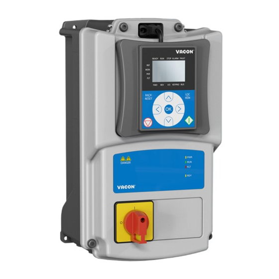
Vacon 20 X - Simple operator panel
1.
V
20 X - S
ACON
1.1
Mounting instructions
Document code: DPD01577A
1.1.1
QDSH Simple operator panel kit
Figure 1. The Simple operator panel option spare kit (MU2 example) .
Frame
Description and type code
size
MU2 QDSH option spare kit
MU2
MU3 QDSH option spare kit
MU3
Service support: find your nearest Vacon service center at www.vacon.com
IMPLE OPERATOR PANEL
Main switch 40A NLT40 and operator
60S01208
Main switch 40A NLT40 and operator
60S01209
Table 1. Simple operator panel kit content.
Item
panel assembly
MU2 cover for main switch
M4x14 screw
M5x23 screws
panel assembly
MU3 cover for main switch
M4x14 screw
M5x23 screws
vacon • 1
Quantity
1
1
2
4
1
1
2
6
1
Advertisement

Subscribe to Our Youtube Channel
Related Manuals for Danfoss VACON 20 X


Summary of Contents for Danfoss VACON 20 X
- Page 1 Vacon 20 X - Simple operator panel vacon • 1 20 X - S ACON IMPLE OPERATOR PANEL Mounting instructions Document code: DPD01577A 1.1.1 QDSH Simple operator panel kit Figure 1. The Simple operator panel option spare kit (MU2 example) .
- Page 2 • 2 Vacon 20 X - Simple operator panel 1.1.2 Installation • Remove the cover from the drive. See the Figure 2. Figure 2. Cover open. • Open only the inlet holes where you need to run the cables. Cables pass through this inlet hole.
- Page 3 Vacon 20 X - Simple operator panel vacon • 3 Figure 3. Simple operator panel connected. • Connect the GROUND wire to the proper terminal (see the yellow-green cable on Figure 3. • Connect the cables from the potentiometer and from the selector to the I/O control terminals.
- Page 4 • 4 Vacon 20 X - Simple operator panel Table 2. Control I/O terminal signal connections to the simple operator panel. Standard I/O terminals Terminal Signal RS485_A Serial bus, negative RS485_B Serial bus, positive RED WIRE +10 Vref Reference output...
Need help?
Do you have a question about the VACON 20 X and is the answer not in the manual?
Questions and answers