Advertisement
Vacon 20 X - Mains switch installation
1.
V
20 X - M
ACON
1.1
Mounting instructions
Document code: DPD01585A
1.1.1
QDSS Mains switch kit
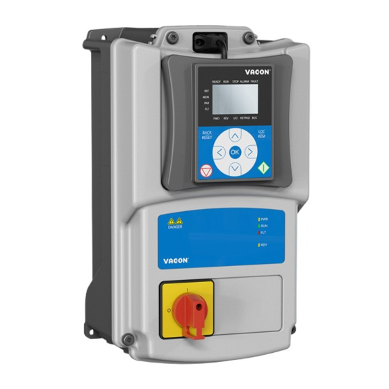
Figure 1. The mains switch option spare kit (MU2 example) .
Frame
Description and type code
size
MU2 QDSS option spare kit
MU2
MU3 QDSS option spare kit
MU3
Service support: find your nearest Vacon service center at www.vacon.com
AINS SWITCH INSTALLATION
60S01128
60S01129
Table 1. Mains switch kit content.
Item
Main switch 40A NLT40 assembly
MU2 cover for main switch
M4x14 screw
M5x23 screws
Main switch 40A NLT40 assembly
MU3 cover for main switch
M4x14 screw
M5x23 screws
vacon • 1
Quantity
1
1
2
4
1
1
2
6
1
Advertisement
Table of Contents

Related Manuals for Danfoss VACON 20 X


Summary of Contents for Danfoss VACON 20 X
- Page 1 Vacon 20 X - Mains switch installation vacon • 1 20 X - M ACON AINS SWITCH INSTALLATION Mounting instructions Document code: DPD01585A 1.1.1 QDSS Mains switch kit Figure 1. The mains switch option spare kit (MU2 example) . Frame...
- Page 2 • 2 Vacon 20 X - Mains switch installation 1.1.2 Installation • Remove the cover from the drive. See the Figure 2. Figure 2. Cover open. • Open only the inlet holes where you need to run the cables. Cables pass through this inlet hole.
- Page 3 Vacon 20 X - Mains switch installation vacon • 3 Figure 3. Mains switch and cables connected. • Connect the GROUND wire to the proper terminal (see the yellow-green cable on Figure 3. Service support: find your nearest Vacon service center at www.vacon.com...
- Page 4 • 4 Vacon 20 X - Mains switch installation • Mount the plastic cover onto the drive with its screws and the HMI cap: the installation process has been completed. See Figure 4. Figure 4. Mount the plastic cover.
Need help?
Do you have a question about the VACON 20 X and is the answer not in the manual?
Questions and answers