Sign In
Upload
Manuals
Brands
Danfoss Manuals
DC Drives
VACON 100 HVAC
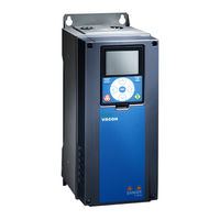
User Manuals: Danfoss VACON 100 HVAC Speed Drive
Manuals and User Guides for Danfoss VACON 100 HVAC Speed Drive. We have
1
Danfoss VACON 100 HVAC Speed Drive manual available for free PDF download: Operating Manual
Danfoss VACON 100 HVAC Operating Manual (148 pages)
Wall-mounted Drives
Brand:
Danfoss
| Category:
DC Drives
| Size: 7 MB
Table of Contents
Table of Contents
3
1 Introduction
7
Additional Resources
7
Disposal
7
Type Approvals and Certifications
7
2 Safety
9
Safety Symbols
9
Danger and Warnings
9
Cautions and Notices
11
3 Product Overview
13
Manual Version
13
Package Label
13
Description of the Type Code
14
Enclosure Sizes
15
4 Receiving the Delivery
19
Checking the Delivery
19
Accessories
19
Accessories Bag, MR4
19
Accessories Bag, MR5
19
Accessories Bag, MR6
20
Accessories Bag, MR7
20
Accessories Bag, MR8
21
Accessories Bag, MR9
21
Storing the Product
22
Lifting the Enclosure Sizes MR8 and MR9
22
Using the Product Modified Label
23
5 Mounting
25
Wall-Mounting Requirements
25
Flange-Mounting Requirements
25
Cooling Requirements
27
General Cooling Requirements
27
Cooling
27
Necessary Quantity of Cooling Air
30
6 Electrical Installation
31
Cable Connections
31
General Cable Requirements
31
UL Standards on Cabling
32
Cable Selection and Dimensioning
32
Cable Selection and Dimensioning, North America
32
Fuse Selection
33
Fuse Selection, North America
33
Brake Resistor Cables
33
EMC-Compliant Installation
34
Installation in a Corner-Grounded Network
35
Grounding
35
Get Access and Locate the Terminals
36
Get Access and Locate the Terminals for MR4-MR7
36
Get Access and Locate the Terminals for MR8
38
Get Access and Locate the Terminals for MR9
40
Installation of Cables
43
Additional Instructions for Cable Installation
43
Installing the Cables, MR4-MR7
44
Installing the Cables, MR8-MR9
48
Installation in an IT System
53
Installing the AC Drive in an IT System, MR4-MR6
53
Installing the AC Drive in an IT System, MR7
55
Installing the AC Drive in an IT System, MR8
58
Installing the AC Drive in an IT System, MR9
60
Installation in a Marine Environment
63
7 Control Unit
64
Control Unit Components
64
Control Unit Cabling
65
Selection of the Control Cables
65
Control Unit Terminals
65
DIP Switches on the Control Unit
67
Selection of Terminal Functions with DIP Switches
67
Isolation of the Digital Inputs from Ground
69
Fieldbus Connection
69
Fieldbus Terminals
69
Internal Fieldbuses in VACON® 100 Products
70
General Cabling Instructions for Fieldbus
71
Cable Routing
71
Strain Relief
73
Ethernet Commissioning and Cabling
73
General Cabling Instructions for Ethernet
73
Grounding the Cable Shield
73
Using Fieldbus through an Ethernet Cable
75
Danfoss A/S © 2019.05 Aq298036140958En
76
RS485 Commissioning and Cabling
78
General Cabling Instructions for RS485
78
Grounding the Cable Shield
79
The RS485 Bus Biasing
80
Using Fieldbus through an RS485 Cable
80
Available Option Boards
84
Option Board Installation
85
Battery for the Real-Time Clock (RTC)
87
Galvanic Isolation Barriers
87
Description of the Control Panel
88
Control Panel and the Keypad
88
Displays of the Control Panel
89
8 Commissioning
91
Safety Checks before Starting the Commissioning
91
Commissioning the AC Drive
92
Measuring the Cable and Motor Insulation
92
Insulation Checks of the Motor Cable
93
Insulation Checks of the Mains Cable
93
Insulation Checks of the Motor
93
Checking the AC Drive after Commissioning
94
9 Maintenance
95
Maintenance Schedule
95
10 Specifications
96
Weight of the Drive
96
Dimensions
96
Dimensions for Wall-Mounting
96
Dimensions for Wall-Mounting for MR4
96
Dimensions for Wall-Mounting for MR5
97
Dimensions for Wall-Mounting for MR6
98
Dimensions for Wall-Mounting for MR7
99
Dimensions for Wall-Mounting for MR8
100
Dimensions for Wall-Mounting for MR9
101
Dimensions for Flange-Mounting
102
Dimensions for Flange-Mounting for MR4
102
Dimensions for Flange-Mounting for MR5
103
Dimensions for Flange-Mounting for MR6
104
Dimensions for Flange-Mounting for MR7
105
Cable and Fuse Sizes
105
List of Cable and Fuse Size Information
105
Cable and Fuse Sizes, Mains Voltage 208-240 V and 380-500 V
106
Cable and Fuse Sizes, Mains Voltage 525-690
107
Cable and Fuse Sizes, Mains Voltage 208-240 V and 380-500 V, North America
109
Cable and Fuse Sizes, Mains Voltage 525-690 V, North America
111
Cable Stripping Lengths
112
Tightening Torques of the Terminals
113
Power Ratings
114
Power Ratings of VACON® 100 INDUSTRIAL, 208-240
114
Power Ratings of VACON® 100 INDUSTRIAL, 380-500
116
Power Ratings of VACON® 100 INDUSTRIAL, 525-600
117
Power Ratings of VACON® 100 INDUSTRIAL, 525-690
118
Power Ratings of VACON® 100 FLOW, 208-240
119
Power Ratings of VACON® 100 FLOW, 380-500
120
Power Ratings of VACON® 100 FLOW, 525-600
121
Power Ratings of VACON® 100 FLOW, 525-690
122
Power Ratings of VACON® 100 HVAC, 208-240
123
Power Ratings of VACON® 100 HVAC, 380-500
124
Overload Capability
124
Brake Resistor Ratings
126
Brake Resistance in Light Duty and Heavy Duty
126
Brake Resistor Types, Mains Voltage 208-240 V and 380-500
127
Brake Resistor Types, Mains Voltage 525-690
127
Brake Resistance and Brake Power, Mains Voltage 208-240 V
128
Brake Resistance and Brake Power, Mains Voltage 380-500
129
Brake Resistance and Brake Power, Mains Voltage 525-600
129
Brake Resistance and Brake Power, Mains Voltage 525-690
129
Control Connections
130
Technical Data, VACON® 100 INDUSTRIAL
133
Technical Data, VACON® 100 FLOW
138
Technical Data, VACON® 100 HVAC
142
Advertisement
Advertisement
Related Products
Danfoss VACON OPTEA
Danfoss Vacon OPTBL
Danfoss Vacon OPTBM
Danfoss Vacon OPTBN
Danfoss VACON 3000
Danfoss VLT 5016
Danfoss VFD500-045G/055PT4
Danfoss VFD500-250G/280PT4
Danfoss VFD500-315G/355PT4
Danfoss VFD500-560G/630PT4
Danfoss Categories
Controller
DC Drives
Thermostat
Control Unit
Air Compressor
More Danfoss Manuals
Login
Sign In
OR
Sign in with Facebook
Sign in with Google
Upload manual
Upload from disk
Upload from URL