Siemens SIMATIC Ident System Manual
Hide thumbs
Also See for SIMATIC Ident:
- System manual (290 pages) ,
- Function manual (142 pages) ,
- Operating manual (80 pages)
Table of Contents
Advertisement
Quick Links
Advertisement
Table of Contents

Related Manuals for Siemens SIMATIC Ident


Summary of Contents for Siemens SIMATIC Ident
- Page 3 ___________________ SIMATIC RF200 Introduction ___________________ Safety notes ___________________ SIMATIC Ident System overview ___________________ RF200 system planning RFID systems SIMATIC RF200 ___________________ Readers ___________________ Antennas System Manual ___________________ Transponder ___________________ System integration ___________________ System diagnostics ___________________ Appendix 07/2015 J31069-D0227-U001-A9-7618...
- Page 4 Note the following: WARNING Siemens products may only be used for the applications described in the catalog and in the relevant technical documentation. If products and components from other manufacturers are used, these must be recommended or approved by Siemens. Proper transport, storage, installation, assembly, commissioning, operation and maintenance are required to ensure that the products operate safely and without any problems.
-
Page 5: Table Of Contents
Table of contents Introduction ............................15 Abbreviations and naming conventions .................. 16 Safety notes ............................17 System overview ........................... 19 RFID components and their function ..................20 Overview of transponders ....................... 23 RF200 system planning......................... 25 Fundamentals of application planning ..................25 4.1.1 Selection criteria for SIMATIC RF200 components .............. - Page 6 Table of contents Further information ......................... 87 Readers ..............................89 SIMATIC RF210R ........................90 5.1.1 Features ..........................90 5.1.2 RF210R ordering data ......................90 5.1.3 Pin assignment RF210R with RS422 interface ..............91 5.1.4 Display elements of the RF210R reader ................91 5.1.5 Minimum distance between RF210R readers ................
- Page 7 Table of contents 5.6.3 Pin assignment RF260R ....................... 122 5.6.4 Display elements of the RF260R reader ................122 5.6.5 Minimum distance between several RF260R ............... 123 5.6.6 Technical data of the RF260R reader................... 124 5.6.7 Approvals ..........................126 5.6.8 Dimension drawing ....................... 127 SIMATIC RF290R .........................
- Page 8 Table of contents 6.4.5 Minimum spacing ......................... 160 6.4.6 Technical data ........................161 6.4.7 Dimension drawing ......................162 ANT 30 ..........................163 6.5.1 Features ..........................163 6.5.2 Ordering data ........................163 6.5.3 Transmission window ......................164 6.5.4 Flush-mounted in metal ....................... 165 6.5.5 Minimum spacing .........................
- Page 9 Table of contents 7.3.5 Dimension drawing ....................... 195 MDS D124 ..........................196 7.4.1 Characteristics ........................196 7.4.2 Ordering data ........................196 7.4.3 Mounting on metal ........................ 197 7.4.4 Technical specifications ......................198 7.4.5 Use of the MDS D124 in hazardous area ................199 7.4.6 Dimension drawing .......................
- Page 10 Table of contents 7.11.3 Technical data ........................228 7.11.4 Dimension drawing ......................229 7.12 MDS D324 ..........................230 7.12.1 Characteristics ........................230 7.12.2 Ordering data ........................230 7.12.3 Metal-free area ........................231 7.12.4 Technical specifications ....................... 232 7.12.5 Dimension drawing ......................233 7.13 MDS D339 ..........................
- Page 11 Table of contents 7.19 MDS D425 ..........................262 7.19.1 Characteristics ........................262 7.19.2 Ordering data ........................263 7.19.3 Application example of MDS D425 ..................263 7.19.4 Technical specifications ......................264 7.19.5 Dimension drawing ....................... 265 7.20 MDS D426 ..........................266 7.20.1 Characteristics ........................
- Page 12 Table of contents 7.27 MDS D526 ..........................293 7.27.1 Characteristics ........................293 7.27.2 Ordering data ........................293 7.27.3 Technical specifications ....................... 294 7.27.4 Dimension drawing ......................295 7.28 MDS D528 ..........................296 7.28.1 Characteristics ........................296 7.28.2 Ordering data ........................296 7.28.3 Application example ......................
- Page 13 Table of contents Ordering data ........................340 Service & Support ......................... 350 Glossary ............................. 353 Index..............................359 SIMATIC RF200 System Manual, 07/2015, J31069-D0227-U001-A9-7618...
- Page 14 Table of contents SIMATIC RF200 System Manual, 07/2015, J31069-D0227-U001-A9-7618...
-
Page 15: Introduction
● RS-422 for connecting to the communications modules ● RS-232 with a simple ASCII protocol for connection to PCs and third-party controllers ● IO-Link for connection to IO Link masters from Siemens and third-party controllers Readers with an internal antenna have a particularly compact design (RF210R/RF220R/RF240R/RF260R). -
Page 16: Abbreviations And Naming Conventions
Introduction 1.1 Abbreviations and naming conventions ● Operating instructions "RF310M" (https://support.industry.siemens.com/cs/us/en/view/51812642) ● Product information "RF200 command set" (https://support.industry.siemens.com/cs/us/en/view/44864850) History The following issues of the SIMATIC RF200 system manual have been published: Output Note 03/2011 First edition 05/2011 Expansion of the documentation with the addition of the device variant RF260R with... -
Page 17: Safety Notes
Safety notes SIMATIC RFID products comply with the salient safety specifications to IEC, VDE, EN, UL and CSA. If you have questions about the validity of the installation in the planned environment, please contact your service representative. NOTICE Alterations to the devices are not permitted. Failure to observe this requirement shall constitute a revocation of the radio equipment approval, CE approval and manufacturer's warranty. - Page 18 Safety notes SIMATIC RF200 System Manual, 07/2015, J31069-D0227-U001-A9-7618...
-
Page 19: System Overview
System overview SIMATIC RF200 is an inductive identification system that is compatible with the ISO 15693 standard and was specially designed for use in industrial production for the control and optimization of material flows. In contrast to SIMATIC RF300, SIMATIC RF200 is intended for RFID applications where performance requirements are not very high, for example with regard to data volume, transfer rate or diagnostics options. -
Page 20: Rfid Components And Their Function
System overview 3.1 RFID components and their function RFID components and their function RF200 system components Figure 3-1 RF200 system overview SIMATIC RF200 System Manual, 07/2015, J31069-D0227-U001-A9-7618... - Page 21 System overview 3.1 RFID components and their function Table 3- 1 Possible reader-transponder combinations Tran- RF210R/ RF220R RF240R RF250R RF260R RF290R RF310M sponder RF210M with ANT 3 ANT 8 ANT 12 ANT 18 ANT 30 ○ ✓ ○ ○ ✓ ✓...
- Page 22 System overview 3.1 RFID components and their function Tran- RF210R/ RF220R RF240R RF250R RF260R RF290R RF310M sponder RF210M with ANT 3 ANT 8 ANT 12 ANT 18 ANT 30 ✓ ✓ ✓ ✓ ✓ ✓ ✓ ✓ D522 ✓ ✓ ✓...
-
Page 23: Overview Of Transponders
System overview 3.2 Overview of transponders Overview of transponders Overview of typical areas of application of ISO transponders for RF200 Transponder Area of application MDS D100 From simple identification such as electronic barcode replacement or supplementation, through ware- house and distribution logistics, right up to product identification. With this transponder, the maximum ranges are achieved in combination with the SIMATIC RF260R reader. - Page 24 System overview 3.2 Overview of transponders Transponder Area of application MDS D400 Simple identification such as electronic barcode replacement/supplements, from warehouse and distribu- tion logistics right through to product identification. MDS D421 The MDS D421 is designed for tool coding according to DIN 69873. It can be used wherever small data carriers and exact positioning are required, e.g.
-
Page 25: Rf200 System Planning
RF200 system planning Fundamentals of application planning 4.1.1 Selection criteria for SIMATIC RF200 components Assess your application according to the following criteria, in order to choose the right SIMATIC RF200 components: ● Static or dynamic data transfer ● Data volume to be transferred ●... - Page 26 RF200 system planning 4.1 Fundamentals of application planning The picture below shows the transmission window of the SIMATIC RF210R and SIMATIC RF220R readers between transponder and reader: Operating distance between transponder and reader Limit distance (maximum clear distance between upper surface of the reader and the tran- sponder, at which the transmission can still function under normal conditions) Diameter of a transmission window Intersection of the axes of symmetry of the transponder...
- Page 27 RF200 system planning 4.1 Fundamentals of application planning The figure below shows the transmission window of the SIMATIC RF240R and SIMATIC RF260R readers between transponder and reader: Operating distance between transponder and reader Limit distance (maximum clear distance between upper surface of the reader and the tran- sponder, at which the transmission can still function under normal conditions) Length of a transmission window Field centerpoint...
-
Page 28: Width Of The Transmission Window
RF200 system planning 4.1 Fundamentals of application planning From the diagrams above, it can also be seen that operation is possible within the area between S and S . The active operating area reduces as the distance increases, and shrinks to a single point at distance S . -
Page 29: Impact Of Secondary Fields
RF200 system planning 4.1 Fundamentals of application planning 4.1.4 Impact of secondary fields Secondary fields in the range from 0 mm to 30% of the limit distance (S ) generally always exist. They should, however, only be used during configuration in exceptional cases, since the read/write distances are very limited. - Page 30 RF200 system planning 4.1 Fundamentals of application planning Secondary fields without shielding The following graphic shows typical primary and secondary fields, if no shielding measures are taken. ① Main field ② Secondary field Figure 4-4 Secondary field without shielding In this arrangement, the reader can also read tags via the secondary field. Shielding is required in order to prevent unwanted reading via the secondary field, as shown and described in the following.
- Page 31 RF200 system planning 4.1 Fundamentals of application planning Secondary fields with shielding The following graphic shows typical primary and secondary fields, with metal shielding this time. The metal shielding prevents the reader from detecting tags via the secondary field. ① Main field ②...
-
Page 32: Permissible Directions Of Motion Of The Transponder
RF200 system planning 4.1 Fundamentals of application planning 4.1.5 Permissible directions of motion of the transponder Detection area and direction of motion of the transponder The transponder and reader have no polarization axis, i.e. the transponder can come in from any direction, assume any position as parallel as possible to the reader, and cross the transmission window. -
Page 33: Operation In Static And Dynamic Mode
RF200 system planning 4.1 Fundamentals of application planning 4.1.6 Operation in static and dynamic mode Operation in static mode If working in static mode, the transponder can be operated up to the limit distance (S ). The transponder must then be positioned exactly over the reader: Figure 4-7 Operation in static mode Note... -
Page 34: Dwell Time Of The Transponder
RF200 system planning 4.1 Fundamentals of application planning 4.1.7 Dwell time of the transponder The dwell time is the time in which the transponder remains within the transmission window of a reader. The reader can exchange data with the transponder during this time. The dwell time is calculated thus: Dwell time of the transponder Length of the transmission window... -
Page 35: Communication Between Communication Module, Reader And Transponder
RF200 system planning 4.1 Fundamentals of application planning 4.1.8 Communication between communication module, reader and transponder Aids for calculating the data transmission times User-friendly calculation tools are available for the communications modules ASM 456, RF160C, RF170C and RF180C to calculate data transfer times. The calculation tools can be found on the DVD "RFID Systems Software &... -
Page 36: Field Data Of Transponders And Readers
RF200 system planning 4.2 Field data of transponders and readers Aids for calculating the field data You will also find a tool for calculating field data on the DVD "RFID Systems, Software & Documentation". Using this tool, among other things you can calculate the operating distance (S ), limit distance (S ) and transmission window (L). -
Page 37: Field Data
RF200 system planning 4.2 Field data of transponders and readers 4.2.1 Field data The limit distances (S ) and operating distances (S ) along with the length of the transmission window for each reader-transponder combination are listed in the tables below. Table 4- 1 SIMATIC RF210R field data Length of the transmis-... - Page 38 RF200 system planning 4.2 Field data of transponders and readers Length of the transmis- Operating distance (S Limit distance (S sion window (L MDS D522 1 ... 10 MDS D522 1 ... 10 Special variants MDS D524 2 ... 22 MDS D526 2 ...
- Page 39 RF200 system planning 4.2 Field data of transponders and readers Table 4- 4 Field data SIMATIC RF250R, with ANT 3 Length of the transmis- Operating distance (S Limit distance (S sion window (L MDS D124 1 ... 35 MDS D126 0 ...
- Page 40 RF200 system planning 4.2 Field data of transponders and readers Length of the transmis- Operating distance (S Limit distance (S sion window (L MDS D428 1 ... 8 MDS D460 1 ... 10 MDS D521 0 ... 3 MDS D522 1 ...
- Page 41 RF200 system planning 4.2 Field data of transponders and readers Length of the transmis- Operating distance (S Limit distance (S sion window (L MDS D424 0 ... 34 MDS D425 1 ... 12 MDS D426 0 ... 44 MDS D428 1 ...
- Page 42 RF200 system planning 4.2 Field data of transponders and readers Table 4- 10 Field data SIMATIC RF290R, with ANT D5 (at 4 W) Length of the transmis- Operating distance (S Limit distance (S sion window (L) MDS D100 0 ... 400 MDS D124 0 ...
- Page 43 RF200 system planning 4.2 Field data of transponders and readers Table 4- 12 Field data SIMATIC RF290R, with ANT D10 (at 4 W) Length of the transmission Operating distance (S Limit distance (S window (L) X direction Y direction MDS D100 1050 0 ...
-
Page 44: Minimum Clearances
RF200 system planning 4.2 Field data of transponders and readers 4.2.2 Minimum clearances Minimum distance from transponder to transponder The specified distances refer to a metal-free environment. For a metallic environment, the specified minimum distances must be multiplied by a factor of 1.5. Table 4- 13 Minimum clearances for transponders RF210R... - Page 45 RF200 system planning 4.2 Field data of transponders and readers Table 4- 14 Minimum clearances for transponders RF250R RF290R ANT 3 ANT 8 ANT 12 ANT 18 ANT 30 ANT D5 ANT D6 ANT D10 MDS D100 ≥ 1000 ≥ 1500 ≥...
- Page 46 RF200 system planning 4.2 Field data of transponders and readers Minimum distance from reader to reader Table 4- 15 Minimum distances to readers or antennas RF210R to RF220R to RF240R to ANT x to ANT x RF260R to ANT Dx to RF210R RF220R RF240R...
-
Page 47: Installation Guidelines
RF200 system planning 4.3 Installation guidelines Installation guidelines 4.3.1 Overview The transponder and reader complete with their antennas are inductive devices. Any type of metal in the vicinity of these devices affects their functionality. Some points need to be considered during planning and installation if the values described in the "Field data (Page 37)"... - Page 48 RF200 system planning 4.3 Installation guidelines Flush-mounting Flush-mounting of transponders and readers Problem Flush-mounting of transponders and readers is possible in principle. However, the size of the transmis- sion window is significantly reduced. The following measures can be used to counteract the reduction of the window: Remedy: Enlargement of the non-metallic...
-
Page 49: Effects Of Metal On Different Transponders And Readers
RF200 system planning 4.3 Installation guidelines Mounting of several readers on metal frames or racks Any reader mounted on metal couples part of the field to the metal frame. There is normally no interaction as long as the minimum distance D and metal-free areas a, b are maintained. However, interaction may take place if an iron frame is positioned unfavorably. -
Page 50: Impact Of Metal On The Transmission Window
RF200 system planning 4.3 Installation guidelines 4.3.4 Impact of metal on the transmission window In general, the following points should be considered when mounting RFID components: ● Direct mounting on metal is allowed only in the case of specially approved transponders. ●... -
Page 51: Rf210R
RF200 system planning 4.3 Installation guidelines 4.3.4.1 RF210R The RF210R can be flush-mounted in metal. Please allow for a possible reduction in the field data values. The following table shows the different arrangements for the reader with and without a metallic environment: Case Diagram... - Page 52 RF200 system planning 4.3 Installation guidelines To avoid any influence on the field data, in Case d, the distance a should be ≥ 10 mm. Table 4- 16 Reduction of field data due to metal, range as %: Transponder and RF210R Transponder Reader without direct Reader flush-...
- Page 53 RF200 system planning 4.3 Installation guidelines Transponder Reader without direct Reader flush- metal influence mounted in metal (Case a, b and d) (Case c) MDS D522 metal-free Special variant flush-mounted in metal; distance all round 0 mm MDS D524 metal-free on metal, distance 15 mm flush-mounted in metal;...
-
Page 54: Rf220R
RF200 system planning 4.3 Installation guidelines 4.3.4.2 RF220R The RF220R can be flush-mounted in metal. Please allow for a possible reduction in the field data values. The following table shows the different arrangements for the reader with and without a metallic environment: Case Diagram... - Page 55 RF200 system planning 4.3 Installation guidelines To avoid any influence on the field data, in Case d, the distance a should be ≥ 15 mm. Table 4- 17 Reduction of field data due to metal, range as %: Transponder and RF220R Transponder Reader without direct Reader flush-...
-
Page 56: Rf240R
RF200 system planning 4.3 Installation guidelines Transponder Reader without direct Reader flush- metal influence mounted in metal (Case a, b and d) (Case c) MDS D522 metal-free flush-mounted in metal; distance all round 0 mm MDS D522 metal-free Special variant flush-mounted in metal;... - Page 57 RF200 system planning 4.3 Installation guidelines To avoid any impact on the field data, the distance a should be ≥ 20 mm. Table 4- 18 Reduction of field data due to metal, range as %: Transponder and RF240R Transponder Reader without Reader on Reader flush- direct...
- Page 58 RF200 system planning 4.3 Installation guidelines Transponder Reader without Reader on Reader flush- direct metal mounted in metal metal influence (metal plate) (all round 20 mm) MDS D424 without metal on metal, distance 15 mm flush-mounted in metal; distance all round 25 mm MDS D425 without metal on metal, distance 0 mm...
-
Page 59: Rf250R
RF200 system planning 4.3 Installation guidelines 4.3.4.4 RF250R The RF250R reader is operated with the external antennas ANT 3, 8, 12, 18 and 30. The antennas can be flush-mounted in metal. Please allow for a possible reduction in the field data values. - Page 60 RF200 system planning 4.3 Installation guidelines Transponder RF250R with ANT 3 antenna without met- antenna flush- mounted in metal (all round 20 mm) MDS D425 without metal on metal, distance 0 mm MDS D426 without metal on metal, distance 25 mm flush-mounted in metal;...
- Page 61 RF200 system planning 4.3 Installation guidelines Transponder RF250R with ANT 8 antenna without met- antenna flush- mounted in metal MDS D127 without metal flush-mounted in metal; distance all round 0 mm MDS D421 without metal flush-mounted in metal; distance all round 0 mm MDS D521 without metal flush-mounted in metal;...
- Page 62 RF200 system planning 4.3 Installation guidelines Transponder RF250R with ANT 12 antenna without met- antenna flush- mounted in metal (all round 7 mm) MDS D522 without metal flush-mounted in metal; distance all round 0 mm MDS D528 without metal on metal, distance 0 mm Mounting the transponder on or in metal is only possible with the appropriate spacer or if there is adequate clearance to the metal.
- Page 63 RF200 system planning 4.3 Installation guidelines Transponder RF250R with ANT 18 antenna without met- antenna flush- mounted in metal (all round 10 mm) MDS D425 without metal on metal, distance 0 mm MDS D428 without metal on metal, distance 0 mm MDS D460 without metal on metal, distance 10 mm...
- Page 64 RF200 system planning 4.3 Installation guidelines Transponder RF250R with ANT 30 antenna without met- antenna flush- mounted in metal (all round 20 mm) MDS D160 without metal on metal, distance 10 mm MDS D324 without metal on metal, distance 15 mm flush-mounted in metal;...
-
Page 65: Rf260R
RF200 system planning 4.3 Installation guidelines Transponder RF250R with ANT 30 antenna without met- antenna flush- mounted in metal (all round 20 mm) MDS D528 without metal on metal, distance 0 mm Mounting the transponder on or in metal is only possible with the appropriate spacer or if there is adequate clearance to the metal. - Page 66 RF200 system planning 4.3 Installation guidelines Transponder Reader with- Reader on met- Reader flush- out direct mounted in metal metal influ- (metal plate) (all round 20 mm) ence MDS D126 without metal on metal, distance 25 mm flush-mounted in metal; distance all round 50 mm MDS D139 without metal...
-
Page 67: Rf290R
RF200 system planning 4.3 Installation guidelines Transponder Reader with- Reader on met- Reader flush- out direct mounted in metal metal influ- (metal plate) (all round 20 mm) ence MDS D460 without metal on metal, distance 10 mm MDS D524 without metal on metal, distance 15 mm flush-mounted in metal;... - Page 68 RF200 system planning 4.3 Installation guidelines To avoid any influence on the field data, the distance a should be ≥ 150 or 200 mm. Table 4- 25 Reduction of field data due to metal, range as %: Transponder and RF290R with ANT Transponder RF290R with ANT D5 Antenna on metal...
- Page 69 RF200 system planning 4.3 Installation guidelines Transponder RF290R with ANT D5 Antenna on metal antenna flush- mounted in metal (metal plate) (all round 150 mm) MDS D426 without metal on metal, distance 25 mm flush-mounted in metal; distance all round 50 mm MDS D460 without metal on metal, distance 10 mm...
- Page 70 RF200 system planning 4.3 Installation guidelines Transponder RF290R with ANT D6 Antenna on metal antenna flush- mounted in metal (metal plate) (all round 200 mm) MDS D424 without metal on metal, distance 25 mm MDS D426 without metal on metal, distance 25 mm Mounting the transponder on or in metal is only possible with the appropriate spacer or if there is adequate clearance to the metal.
-
Page 71: Installation And Connection Of 2 To 6 Antennas With One Rf290R Reader
RF200 system planning 4.3 Installation guidelines Transponder RF290R with ANT D10 Antenna on metal antenna flush- mounted in metal (metal plate) (all round 200 mm) MDS D426 without metal on metal, distance 25 mm MDS D524 without metal on metal, distance 25 mm MDS D526 without metal on metal, distance 25 mm... -
Page 72: Installation Options With The Antenna Splitter (2-4 Antennas)
RF200 system planning 4.3 Installation guidelines 4.3.5.1 Installation options with the antenna splitter (2-4 antennas) Possible configurations of the antennas The antenna installations described here have been designed for reading smartlabels (transponders) on goods on conveyor belts, conveyor systems or pallets. A prerequisite is that there are no magnetically conducting materials (e.g. - Page 73 RF200 system planning 4.3 Installation guidelines Installation examples Figure 4-16 Installation example with 2 ANT D6 (portal) Figure 4-17 Installation example with ANT D6 (C arrangement) SIMATIC RF200 System Manual, 07/2015, J31069-D0227-U001-A9-7618...
- Page 74 RF200 system planning 4.3 Installation guidelines Figure 4-18 Installation example with ANT D6 (tunnel) Note The minimum spacings between the antennas for operation with only one reader may be less than the distances described because this configuration has the same phase. SIMATIC RF200 System Manual, 07/2015, J31069-D0227-U001-A9-7618...
-
Page 75: Antenna Installation
RF200 system planning 4.3 Installation guidelines 4.3.5.2 Antenna installation Configuring instructions The antenna installation described below enables detection of transponders moving horizontally through the installation. Depending on the installation (antennas exactly opposite each other or offset in parallel), the label is aligned in parallel with the antennas or arbitrarily. The size of the sensing range depends on the label alignment: Note Remember that the entire acquisition range of the antenna is larger than the transmission... - Page 76 RF200 system planning 4.3 Installation guidelines Required components For installation with ● 2 antennas (gate) ● 3 antennas (C arrangement) ● 4 antennas (tunnel) the following components are required: Table 4- 28 Components required for setting up with 2, 3 or 4 antennas Number for installation Component Article number...
- Page 77 RF200 system planning 4.3 Installation guidelines Metal-free space To guarantee perfect functioning of the individual installation versions, all larger metal parts in the vicinity of the antennas must be removed. Figure 4-19 Metal-free space, side view (based on the example of a tunnel arrangement on a conveyor belt) approx.
- Page 78 RF200 system planning 4.3 Installation guidelines ● The metal parts must not form closed loops or circuits. If necessary, these must be electrically interrupted at one point. ● The metal parts in the immediate vicinity of the antenna must be grounded in a mesh with a good HF connection.
-
Page 79: Installation Options With The Antenna Multiplexer (2-6 Antennas)
RF200 system planning 4.3 Installation guidelines 4.3.5.3 Installation options with the antenna multiplexer (2-6 antennas) You can operate up to six antennas on one reader via the multiplexer. The data is processed sequentially. Antenna switchover is performed in time-multiplex mode, so by connecting several antennas together, the processing time / activation time per antenna is lengthened accordingly. -
Page 80: Chemical Resistance Of The Transponders
RF200 system planning 4.3 Installation guidelines 4.3.6 Chemical resistance of the transponders 4.3.6.1 Overview of the transponders and their housing materials The following sections describe the resistance to chemicals of the various transponders. Resistance to chemicals depends on the housing material used to manufacture the transponders. -
Page 81: Polyphenylene Sulfide (Pps)
RF200 system planning 4.3 Installation guidelines Note Chemical substances not listed The following sections describe the resistance of the various transponders to specific substances. If you require information about chemical substances that are not listed, contact Customer Support. 4.3.6.2 Polyphenylene sulfide (PPS) The data memory has special chemical resistance to solutions up to a temperature of 200 °C. -
Page 82: Polycarbonate (Pc)
RF200 system planning 4.3 Installation guidelines Substance Test conditions Rating Concentration [%] Temperature [°C] FAM testing fluid 80 ℃ ○○ acc. to DIN 51 604-A Toluene 1, 1, 1-Trichloroethane 80 ℃ ○○○○ Xylene Zinc chloride (saturated) 80 ℃ ○○ 75 ℃ ○○○○... -
Page 83: Polyvinyl Chloride (Pvc)
RF200 system planning 4.3 Installation guidelines Explanation of the rating ○○○○ Resistant ○○○ Practically resistant ○○ Conditionally resistant ○ Less resistant Not resistant 4.3.6.4 Polyvinyl chloride (PVC) Table 4- 32 Chemical resistance - polyvinyl chloride (PVC) Substance Test conditions Rating Concentration [%] Temperature [°C] Salt water... - Page 84 RF200 system planning 4.3 Installation guidelines Substance Test conditions Rating Concentration [%] Temperature [°C] Ammonia, liquid, water-free 20 ℃ Ammonium hydroxide 10 % 20 ℃ ○○○○ Ethanol 40 ℃ ○○○○ 60 ℃ ○○○○ Ethyl acrylate 20 ℃ ○○○○ Ethyl glycol 60 ℃...
- Page 85 RF200 system planning 4.3 Installation guidelines Substance Test conditions Rating Concentration [%] Temperature [°C] Dimethyl ether 20 ℃ ○○○○ Dioxane 20 ℃ Developer 40 ℃ ○○○○ Acetic acid 100 % 20 ℃ ○○ Ethanol 60 ℃ ○○○○ Fixing bath 40 ℃ ○○○○...
-
Page 86: Pa6.6 Gf30
RF200 system planning 4.3 Installation guidelines Substance Test conditions Rating Concentration [%] Temperature [°C] Sulfuric acid 40 % 20 ℃ Sulfurous acid 20 ℃ ○○ Soap solution 60 ℃ ○○○○ Sulphates (ammonium..., Na– among 60 ℃ ○○○○ others) Sulfites (ammonium..., Na– among 60 ℃... -
Page 87: Further Information
Explanation of the rating ○○○○ Resistant ○○○ Practically resistant ○○ Conditionally resistant ○ Less resistant Not resistant Further information Further information on "Fundamentals of application planning" and "EMC" can be found in RF300 system manual (https://support.industry.siemens.com/cs/ww/en/view/21738946). SIMATIC RF200 System Manual, 07/2015, J31069-D0227-U001-A9-7618... - Page 88 RF200 system planning 4.4 Further information SIMATIC RF200 System Manual, 07/2015, J31069-D0227-U001-A9-7618...
-
Page 89: Readers
Note IO-Link variants of the RF200 readers The IO-Link variants of the readers are not included in the system manual. You will find these in the "SIMATIC RF200 IO-Link (https://support.industry.siemens.com/cs/ww/en/view/60641859)" operating instructions. SIMATIC RF200 System Manual, 07/2015, J31069-D0227-U001-A9-7618... -
Page 90: Simatic Rf210R
Readers 5.1 SIMATIC RF210R SIMATIC RF210R 5.1.1 Features SIMATIC RF210R Characteristics ① Design RS422 interface ② Status display Application Identification tasks on assembly lines in harsh in- dustrial environments 5.1.2 RF210R ordering data Article number RF210R with RS422 interface (3964R) 6GT2821-1AC10 SIMATIC RF200 System Manual, 07/2015, J31069-D0227-U001-A9-7618... -
Page 91: Pin Assignment Rf210R With Rs422 Interface
"Error codes". The optical error display is only reset if the corresponding reset parameter ("option_1 = 2") is set (see Product infor- mation "SIMATIC RF200 command set" (https://support.industry.siemens.com/cs/us/en/view/44864850)). Only in the "with presence" mode. SIMATIC RF200... -
Page 92: Minimum Distance Between Rf210R Readers
Readers 5.1 SIMATIC RF210R 5.1.5 Minimum distance between RF210R readers RF210R side by side D ≥ 60 mm Figure 5-1 Minimum distance between RF210R readers RF210R face to face ≥ 100 mm Figure 5-2 Face-to-face distance between two RF210Rs SIMATIC RF200 System Manual, 07/2015, J31069-D0227-U001-A9-7618... -
Page 93: Technical Specifications Of The Rf210R Reader
Readers 5.1 SIMATIC RF210R 5.1.6 Technical specifications of the RF210R reader Table 5- 1 Technical specifications of the RF210R reader 6GT2821-1AC10 Product type designation SIMATIC RF210R Radio frequencies Operating frequency, rated value 13.56 MHz Electrical data Maximum range 20 mm Maximum data transmission rate reader ↔... -
Page 94: Approvals
(operating voltage, presence, error) 5.1.7 Approvals FCC information Siemens SIMATIC RF210R (MLFB 6GT2821-1AC10) FCC ID NXW-RF210R This device complies with part 15 of the FCC rules. Operation is subject to the following two conditions: (1) This device may not cause harmful interference, and (2) this device must accept any interference received, including interference that may cause undesired operation. -
Page 95: Dimension Drawing
Readers 5.1 SIMATIC RF210R IC information This device complies with Industry Canada licence-exempt RSS standard(s). Operation is subject to the following two conditions: (1) This device may not cause interference, and (2) this device must accept any interference, including interference that may cause undesired operation of the device. -
Page 96: Simatic Rf210M
Readers 5.2 SIMATIC RF210M SIMATIC RF210M 5.2.1 Features SIMATIC RF210M Characteristics ① Design RS422 interface ② Status display Application Reader for hand work and rework places, picking, track and trace, tool Ident 5.2.2 Ordering data RF210M Article number RF210M with RS-422 interface (3964R) 6GT2823-0AA00 SIMATIC RF200 System Manual, 07/2015, J31069-D0227-U001-A9-7618... -
Page 97: Installing The Rf210M Reader
Readers 5.2 SIMATIC RF210M 5.2.3 Installing the RF210M reader The following figure shows the completely mounted reader. Note that you can mount the ① suspension bracket at two different points . If you do not mount the handle, we ② recommend that you close the opening with the protective cap. -
Page 98: Display Elements Of The Rf210M Reader
"Error codes". The optical error display is only reset if the corresponding reset parameter ("option_1 = 2") is set (see Product infor- mation "SIMATIC RF200 command set" (https://support.industry.siemens.com/cs/ww/en/view/44864850)). Only in the "with presence" mode. 5.2.6 Technical specifications of the RF210M reader... - Page 99 Readers 5.2 SIMATIC RF210M 6GT2823-0AA00 Mechanical specifications Housing Material • • Color Black • • Supply voltage, current consumption, power loss Supply voltage 24 VDC Typical current consumption 50 mA Permitted ambient conditions Ambient temperature During operation -20 … +50 °C •...
-
Page 100: Approvals
5.2 SIMATIC RF210M 5.2.7 Approvals FCC information Siemens SIMATIC RF210R (MLFB 6GT2821-1AC10) FCC ID NXW-RF210R This device complies with part 15 of the FCC rules. Operation is subject to the following two conditions: (1) This device may not cause harmful interference, and (2) this device must accept any interference received, including interference that may cause undesired operation. -
Page 101: Dimension Drawing
Readers 5.2 SIMATIC RF210M 5.2.8 Dimension drawing Figure 5-5 Dimension drawing RF210M All dimensions in mm, tolerances ± 1 mm SIMATIC RF200 System Manual, 07/2015, J31069-D0227-U001-A9-7618... -
Page 102: Simatic Rf220R
Readers 5.3 SIMATIC RF220R SIMATIC RF220R 5.3.1 Features SIMATIC RF220R Characteristics ① Design RS422 interface ② Status display Application Identification tasks on assembly lines in harsh in- dustrial environments 5.3.2 RF220R ordering data Article number RF220R with RS-422 interface (3964R) 6GT2821-2AC10 SIMATIC RF200 System Manual, 07/2015, J31069-D0227-U001-A9-7618... -
Page 103: Rf220R Pin Assignment With Rs422 Interface
"Error codes". The optical error display is only reset if the corresponding reset parameter ("option_1 = 2") is set (see Product infor- mation "SIMATIC RF200 command set" (https://support.industry.siemens.com/cs/us/en/view/44864850)). Only in the "with presence" mode. SIMATIC RF200... -
Page 104: Minimum Distance Between Rf220R Readers
Readers 5.3 SIMATIC RF220R 5.3.5 Minimum distance between RF220R readers RF220R side by side D ≥ 100 mm Figure 5-6 Minimum distance between RF220R readers RF220R face to face ≥ 150 mm Figure 5-7 Face-to-face distance between two RF220Rs SIMATIC RF200 System Manual, 07/2015, J31069-D0227-U001-A9-7618... -
Page 105: Technical Specifications Of The Rf220R Reader
Readers 5.3 SIMATIC RF220R 5.3.6 Technical specifications of the RF220R reader Table 5- 3 Technical specifications of the RF220R reader 6GT2821-2AC10 Product type designation SIMATIC RF220R Radio frequencies Operating frequency, rated value 13.56 MHz Electrical data Maximum range 35 mm Maximum data transmission rate reader ↔... -
Page 106: Approvals
(operating voltage, presence, error) 5.3.7 Approvals FCC information Siemens SIMATIC RF220R (MLFB 6GT2821-2AC10) FCC ID NXW-RF220R This device complies with part 15 of the FCC rules. Operation is subject to the following two conditions: (1) This device may not cause harmful interference, and (2) this device must accept any interference received, including interference that may cause undesired operation. -
Page 107: Dimension Drawing
Readers 5.3 SIMATIC RF220R IC information This device complies with Industry Canada licence-exempt RSS standard(s). Operation is subject to the following two conditions: (1) This device may not cause interference, and (2) this device must accept any interference, including interference that may cause undesired operation of the device. -
Page 108: Simatic Rf240R
Readers 5.4 SIMATIC RF240R SIMATIC RF240R 5.4.1 Features SIMATIC RF240R Characteristics ① Structure RS-422 or RS-232 interface ② Operating indicator Field of application Identification tasks on assembly lines in harsh in- dustrial environments 5.4.2 RF240R ordering data Article number RF240R with RS-422 interface (3964R) 6GT2821-4AC10 RF240R with RS-232 interface (3964R) 6GT2821-4AC11... -
Page 109: Pin Assignment Rf240R
"Error codes". The optical error display is only reset if the corresponding reset parameter ("option_1 = 2") is set (see Product infor- mation "SIMATIC RF200 command set" (https://support.industry.siemens.com/cs/ww/en/view/44864850)). Only in the "with presence" mode. SIMATIC RF200... -
Page 110: Minimum Distance Between Several Rf240R Readers
Readers 5.4 SIMATIC RF240R 5.4.5 Minimum distance between several RF240R readers RF240R readers side by side D ≥ 120 mm (with 2 readers) D ≥ 200 mm (with more than 2 readers) Figure 5-9 Minimum distance between several RF240R readers RF240R face-to-face ≥... -
Page 111: Technical Specifications Of The Rf240R Reader
Readers 5.4 SIMATIC RF240R 5.4.6 Technical specifications of the RF240R reader Table 5- 4 Technical specifications of the RF240R reader 6GT2821-4AC10 6GT2821-4AC11 6GT2821-4AC40 Product type designation SIMATIC RF240R Radio frequencies Operating frequency, rated value 13.56 MHz Electrical data Maximum range 65 mm Maximum data transmission rate reader ↔... - Page 112 Readers 5.4 SIMATIC RF240R 6GT2821-4AC10 6GT2821-4AC11 6GT2821-4AC40 Supply voltage, current consumption, power loss Supply voltage 24 VDC Typical current consumption 25 mA Permitted ambient conditions Ambient temperature During operation -20 … +70 °C • • During transportation and storage -25 … +85 °C •...
-
Page 113: Approvals
5.4.7 Approvals FCC information Siemens SIMATIC RF240R (MLFB 6GT2821-4AC10) FCC ID NXW-RF240R Siemens SIMATIC RF240R (MLFB 6GT2821-4AC11) FCC ID NXW-RF240R Siemens SIMATIC RF240R (MLFB 6GT2821-4AC40) FCC ID NXW-RF240R This device complies with part 15 of the FCC rules. Operation is subject to the following two... -
Page 114: Dimension Drawing
Readers 5.4 SIMATIC RF240R 5.4.8 Dimension drawing Figure 5-11 Dimension drawing RF240R Dimensions in mm SIMATIC RF200 System Manual, 07/2015, J31069-D0227-U001-A9-7618... -
Page 115: Simatic Rf250R
Readers 5.5 SIMATIC RF250R SIMATIC RF250R 5.5.1 Features SIMATIC RF250R Characteristics ① Structure RS-422 or RS-232 interface ② Operating indicator ③ Antenna connector, M8 Area of application Identification tasks on assembly lines in harsh in- dustrial environments Note Reader requires external antennas Note that the RF250R reader is designed only for operation with external antennas and can only be operated in conjunction with the antennas ANT 3, ANT 8, ANT 12, ANT 18 or ANT 30. -
Page 116: Pin Assignment Rf250R
"Error codes". The optical error display is only reset if the corresponding reset parameter ("option_1 = 2") is set (see Product infor- mation "SIMATIC RF200 command set" (https://support.industry.siemens.com/cs/ww/en/view/44864850)). Only in the "with presence" mode. SIMATIC RF200... -
Page 117: Technical Specifications Of The Rf250R Reader
Readers 5.5 SIMATIC RF250R 5.5.5 Technical specifications of the RF250R reader Table 5- 5 Technical specifications of the RF250R reader 6GT2821-5AC10 6GT2821-5AC40 Product type designation SIMATIC RF250R Radio frequencies Operating frequency, rated value 13.56 MHz Electrical data Maximum range 35 mm Maximum data transmission rate reader ↔... -
Page 118: Approvals
3-color LED 5.5.6 Approvals FCC information Siemens SIMATIC RF250R (MLFB 6GT2821-5AC10) FCC ID NXW-RF250R Siemens SIMATIC RF250R (MLFB 6GT2821-5AC40) FCC ID NXW-RF250R This device complies with part 15 of the FCC rules. Operation is subject to the following two conditions:... - Page 119 Readers 5.5 SIMATIC RF250R Note This equipment has been tested and found to comply with the limits for a Class A digital device, pursuant to part 15 of the FCC Rules. These limits are designed to provide reasonable protection against harmful interference when the equipment is operated in a commercial environment.
-
Page 120: Dimension Drawing
Readers 5.5 SIMATIC RF250R 5.5.7 Dimension drawing Figure 5-12 Dimension drawing RF250R Dimensions in mm SIMATIC RF200 System Manual, 07/2015, J31069-D0227-U001-A9-7618... -
Page 121: Simatic Rf260R
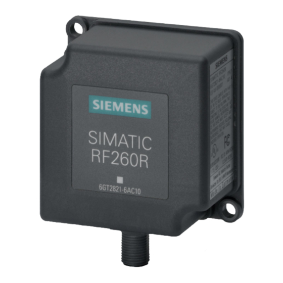
Readers 5.6 SIMATIC RF260R SIMATIC RF260R 5.6.1 Features SIMATIC RF260R Characteristics ① Structure RS-422 or RS-232 interface ② Operating indicator Field of application Identification tasks on assembly lines in harsh in- dustrial environments 5.6.2 Ordering data for RF260R Article number RF260R with RS-422 interface (3964R) 6GT2821-6AC10 RF260R with RS-232 interface (3964R) -
Page 122: Pin Assignment Rf260R
"Error codes". The optical error display is only reset if the corresponding reset parameter ("option_1 = 2") is set (see Product infor- mation "SIMATIC RF200 command set" (https://support.industry.siemens.com/cs/us/en/view/44864850)). Only in the "with presence" mode. SIMATIC RF200... -
Page 123: Minimum Distance Between Several Rf260R
Readers 5.6 SIMATIC RF260R 5.6.5 Minimum distance between several RF260R RF260R side by side D ≥ 150 mm (with 2 readers) D ≥ 250 mm (with more than 2 readers) Figure 5-13 Minimum distance between several RF260R RF260R face to face ≥... -
Page 124: Technical Data Of The Rf260R Reader
Readers 5.6 SIMATIC RF260R 5.6.6 Technical data of the RF260R reader Table 5- 6 Technical specifications of the RF260R reader 6GT2821-6AC10 6GT2821-6AC11 6GT2821-6AC40 Product type designation SIMATIC RF260R Radio frequencies Operating frequency, rated value 13.56 MHz Electrical data Maximum range 135 mm Maximum data transmission rate reader ↔... - Page 125 Readers 5.6 SIMATIC RF260R 6GT2821-6AC10 6GT2821-6AC11 6GT2821-6AC40 Supply voltage, current consumption, power loss Supply voltage 24 VDC Typical current consumption 50 mA Permitted ambient conditions Ambient temperature During operation -20 … +70 °C • • During transportation and storage -25 … +80 °C •...
-
Page 126: Approvals
5.6.7 Approvals FCC information Siemens SIMATIC RF260R (MLFB 6GT2821-6AC10) FCC ID NXW-RF260R Siemens SIMATIC RF260R (MLFB 6GT2821-6AC11) FCC ID NXW-RF260R Siemens SIMATIC RF260R (MLFB 6GT2821-6AC40) FCC ID NXW-RF260R This device complies with part 15 of the FCC rules. Operation is subject to the following two... -
Page 127: Dimension Drawing
Readers 5.6 SIMATIC RF260R 5.6.8 Dimension drawing Figure 5-15 Dimension drawing RF260R Dimensions in mm SIMATIC RF200 System Manual, 07/2015, J31069-D0227-U001-A9-7618... -
Page 128: Simatic Rf290R
Readers 5.7 SIMATIC RF290R SIMATIC RF290R 5.7.1 Features SIMATIC RF290R Characteristics ① Design RS-422/RS-232 interface, 24 V power supply ② Digital I/O ③ External antenna ④ Operating display, 4 LEDs: Power (PWR) • Active (ACT) • Present (PRE) • Error (ERR) •... -
Page 129: Ordering Data Rf290R
Readers 5.7 SIMATIC RF290R 5.7.2 Ordering data RF290R Table 5- 7 Ordering data RF290R Article number RF290R 6GT2821-0AC12 with RS-232 interface for PC mode and RS-422 interface for CM mode Table 5- 8 Ordering data - accessories - RF290R Article number 24 V connecting cable 6GT2491-1HH50 RS-232 connecting cable, with 4-pin M12 connector for... -
Page 130: Pin Assignment Rf290R
Readers 5.7 SIMATIC RF290R 5.7.3 Pin assignment RF290R RS422/RS232 Table 5- 9 Pin assignment of the RS-422/RS 232 interface Interface assignment Device end 8- RS-422 RS-232 pin M12 +24 V +24 V - Transmit + Transmit + Receive not used - Receive not used not used... - Page 131 Readers 5.7 SIMATIC RF290R Digital input (DI): The opto-coupler input is electrically isolated from the reader electronics. The external 24 V must be connected to the DI according to the circuit diagram. Make sure that the polarity of the 24 V is correct. The current is limited to < 10 mA by the integrated resistor. NOTICE Reader may be damaged If you exceed the maximum permitted supply voltage, the reader may be damaged.
-
Page 132: Display Elements Of The Rf290R Reader
"Error codes". The optical error display is only reset if the corre- sponding reset parameter ("option_1 = 2") is set (see product information "Product information "SIMATIC RF200 command set" (https://support.industry.siemens.com/cs/ww/en/view/44864850)"). PC mode: permanently lit: Error when connecting the antenna or the interference level... -
Page 133: Installing The Rf290R Reader
Readers 5.7 SIMATIC RF290R 5.7.5 Installing the RF290R reader 5.7.5.1 Wall mounting Use the holes in the housing to screw the device to the wall or onto a horizontal surface. The position of the drill holes is shown in the following figure: Figure 5-17 Drilling pattern for the RF290R (dimensions in mm) A: M4 threaded socket for potential connection of the reader. -
Page 134: Installing On The S7-300 Standard Rail
Readers 5.7 SIMATIC RF290R 5.7.5.2 Installing on the S7-300 standard rail Follow the steps below to mount the RF290R reader on a vertical S7-300 standard rail: 1. Place the device on the upper edge of the S7-300 standard rail (position A). 2. - Page 135 Readers 5.7 SIMATIC RF290R Fit the adapter to the rear of the device as shown in the following figure: Figure 5-19 Mounting the DIN rail adapter Follow the steps below to mount the RF290R reader on a DIN rail: 1. Place the device on the upper edge of the DIN rail (position A). 2.
-
Page 136: Technical Specifications Of The Rf290R Reader
Readers 5.7 SIMATIC RF290R 5.7.6 Technical specifications of the RF290R reader Table 5- 11 Technical specifications of the RF290R reader 6GT2821-0AC12 Product type designation SIMATIC RF290R Radio frequencies Operating frequency, rated value 13.56 MHz Electrical data Maximum range 65 mm Maximum data transmission rate reader ↔... -
Page 137: Approvals
4 LEDs 5.7.7 Approvals FCC information Siemens SIMATIC RF290R (MLFB 6GT2821-0AC12) FCC ID NXW-RF290R This device complies with part 15 of the FCC rules. Operation is subject to the following two conditions: (1) This device may not cause harmful interference, and (2) this device must accept any interference received, including interference that may cause undesired operation. - Page 138 Readers 5.7 SIMATIC RF290R Note This equipment has been tested and found to comply with the limits for a Class A digital device, pursuant to part 15 of the FCC Rules. These limits are designed to provide reasonable protection against harmful interference when the equipment is operated in a commercial environment.
-
Page 139: Note On The Use Of The Rf290R As A Replacement For Slg D10 / Slg D10S
Readers 5.7 SIMATIC RF290R 5.7.8 Note on the use of the RF290R as a replacement for SLG D10 / SLG D10S The RF290R reader is the successor to the MOBY D readers SLG D10 / SLG D10S rounding off the RF200 family; it is operated with external antennas. The following features distinguish the RF290R from the SLG models: Table 5- 12 Differences between the RF290R readers and SLG D10 / SLG D10S... -
Page 140: Dimension Drawing
Readers 5.7 SIMATIC RF290R 5.7.9 Dimension drawing Figure 5-21 Dimensional drawing RF290R (dimensions in mm) SIMATIC RF200 System Manual, 07/2015, J31069-D0227-U001-A9-7618... -
Page 141: Antennas
Antennas Note The RF250R and RF290R readers require external antennas Note that the RF250R and RF290R readers are designed for operation with external antennas. The RF250R reader can only be used in conjunction with the antennas ANT 3, 8, 12, 18 or 30. -
Page 142: Ant 3
Antennas 6.1 ANT 3 ANT 3 6.1.1 Features ANT 3 Characteristics Area of application Small assembly lines Writing/reading distance up to 50 mm (depending on the transponder) Connecting cable 3 m (plug-in antenna cable) Connectable readers RF250R Degree of protection IP67 6.1.2 Ordering data... -
Page 143: Mounting On/In Metal
Antennas 6.1 ANT 3 6.1.3 Mounting on/in metal The tuning of the ANT 3 antenna is optimized for mounting on metal. ① ANT 3 ② Metal Figure 6-1 ANT 3 mounted on metal ① ANT 3 ② Metal = 10 mm Figure 6-2 ANT 3 flush-mounted in metal SIMATIC RF200... -
Page 144: Operating / Limit Distances
Antennas 6.1 ANT 3 6.1.4 Operating / limit distances The operating / limit distances listed in the following table relate to an ANT 3 mounted on metal. Table 6- 3 Operating / limit distances of the transponders RF250R with ANT 3 RF250R with ANT 3 Operating distance (S Limit distance (S... - Page 145 Antennas 6.1 ANT 3 Minimum distances from transponder to transponder (without multitag mode) Table 6- 4 Minimum distances transponder edge to transponder edge MDS D124 / MDS D160 / MDS D324 / MDS D422 / MDS D425 / MDS D522 MDS D423 / MDS D424 / MDS D428 / MDS D460 / MDS D524 / MDS D528 RF250R with ANT 3...
-
Page 146: Technical Data
Antennas 6.1 ANT 3 6.1.6 Technical data 6GT2398-1CD30-0AX0 6GT2398-1CD40-0AX0 Product type designation ANT 3 Electrical data Maximum write/read distance 50 mm ANT ↔ Transponder (S Interfaces Plug connection M8, 4-pin socket on antenna side (with antenna connecting cable: pin cable end) Mechanical specifications Housing Material... -
Page 147: Dimension Drawing
Antennas 6.1 ANT 3 6.1.7 Dimension drawing Figure 6-5 Dimension drawing ANT 3 (all values in mm) SIMATIC RF200 System Manual, 07/2015, J31069-D0227-U001-A9-7618... -
Page 148: Ant 8
Antennas 6.2 ANT 8 ANT 8 6.2.1 Features ANT 8 Characteristics Area of application Tool identification Writing/reading distance up to 4 mm (depending on the transponder) Connecting cable Connectable readers RF250R Degree of protection IP67 6.2.2 Ordering data Table 6- 5 Ordering data ANT 8 Antenna Article number... -
Page 149: Transmission Window
Antennas 6.2 ANT 8 6.2.3 Transmission window Length of the transmission window (= 3 mm) Operating distance between antenna and transponder Limit distance (maximum clear distance between upper surface of the reader and the antenna, at which the transmission can still function under normal conditions) Figure 6-6 Transmission window ANT 8 6.2.4... -
Page 150: Minimum Spacing
Antennas 6.2 ANT 8 6.2.5 Minimum spacing Note Extension of the data transmission time if distance values are undershot If the distance values specified in the tables are undershot, it is possible that the inductive fields will be affected. In this case, the data transmission time can increase unpredictably or a command is aborted with an error. -
Page 151: Technical Data
Antennas 6.2 ANT 8 > 50 mm Figure 6-9 Face-to-face distance between two ANT 8s 6.2.6 Technical data 6GT2398-1CF10 6GT2398-1CF00 Product type designation ANT 8 Electrical data Maximum write/read distance ANT ↔ transponder 4 mm Interfaces Plug connection 4-pin (pin on antenna side) Mechanical specifications Housing Material... -
Page 152: Dimension Drawing
Antennas 6.2 ANT 8 6GT2398-1CF10 6GT2398-1CF00 Permitted ambient conditions Ambient temperature During operation -25 °C ... +70 °C • • During transportation and storage -40 °C ... +85 °C • • Degree of protection to EN 60529 IP67 Shock-resistant to EN 60721-3-7, Class 7 M3 50 g Vibration-resistant to EN 60721-3-7, Class 7 M3 20 g... -
Page 153: Ant 12
Antennas 6.3 ANT 12 ANT 12 6.3.1 Features ANT 12 Characteristics Area of application Tool identification Writing/reading distance up to 16 mm (depending on the transponder) Connecting cable 3 m or 0.6 m Connectable readers RF250R Degree of protection IP67 (front) 6.3.2 Ordering data Table 6- 7... -
Page 154: Transmission Window
Antennas 6.3 ANT 12 6.3.3 Transmission window Length of the transmission window (= 20 mm) Operating distance between antenna and transponder Limit distance (maximum clear distance between upper surface of the reader and the antenna, at which the transmission can still function under normal conditions) Figure 6-11 Transmission window ANT 12 6.3.4... -
Page 155: Minimum Spacing
Antennas 6.3 ANT 12 6.3.5 Minimum spacing Note Extension of the data transmission time if distance values are undershot If the distance values specified in the tables are undershot, it is possible that the inductive fields will be affected. In this case, the data transmission time can increase unpredictably or a command is aborted with an error. -
Page 156: Technical Data
Antennas 6.3 ANT 12 > 100 mm Figure 6-14 Face-to-face distance between two ANT 12s 6.3.6 Technical data 6GT2398-1CC00 6GT2398-1CC10 Product type designation ANT 12 Electrical data Maximum write/read distance ANT ↔ transponder 16 mm Interfaces Plug connection 4-pin (pin on antenna side) Mechanical specifications Housing Material... -
Page 157: Dimension Drawing
Antennas 6.3 ANT 12 6GT2398-1CC00 6GT2398-1CC10 Permitted ambient conditions Ambient temperature During operation -20 °C ... +70 °C • • During transportation and storage -40 °C ... +85 °C • • Degree of protection to EN 60529 IP67 (front) Shock-resistant to EN 60721-3-7, Class 7 M3 50 g Vibration-resistant to EN 60721-3-7, Class 7 M3 20 g... -
Page 158: Ant 18
Antennas 6.4 ANT 18 ANT 18 6.4.1 Features ANT 18 Characteristics Area of application Small assembly lines Writing/reading distance up to 35 mm (depending on the transponder) Connecting cable 3 m or 0.6 m Connectable readers RF250R Degree of protection IP67 (front) 6.4.2 Ordering data... -
Page 159: Transmission Window
Antennas 6.4 ANT 18 6.4.3 Transmission window Length of the transmission window (= 30 mm) Operating distance between antenna and transponder Limit distance (maximum clear distance between upper surface of the reader and the antenna, at which the transmission can still function under normal conditions) Figure 6-16 Transmission window ANT 18 6.4.4... -
Page 160: Minimum Spacing
Antennas 6.4 ANT 18 6.4.5 Minimum spacing Note Extension of the data transmission time if distance values are undershot If the distance values specified in the tables are undershot, it is possible that the inductive fields will be affected. In this case, the data transmission time can increase unpredictably or a command is aborted with an error. -
Page 161: Technical Data
Antennas 6.4 ANT 18 > 100 mm Figure 6-19 Face-to-face distance between two ANT 18s 6.4.6 Technical data 6GT2398-1CA00 6GT2398-1CA10 Product type designation ANT 18 Electrical data Maximum write/read distance ANT ↔ transponder 35 mm Interfaces Plug connection 4-pin (pin on antenna side) Mechanical specifications Housing Material... -
Page 162: Dimension Drawing
Antennas 6.4 ANT 18 6GT2398-1CA00 6GT2398-1CA10 Permitted ambient conditions Ambient temperature During operation -20 °C ... +70 °C • • During transportation and storage -40 °C ... +85 °C • • Degree of protection to EN 60529 IP67 (front) Shock-resistant to EN 60721-3-7, Class 7 M3 50 g Vibration-resistant to EN 60721-3-7, Class 7 M3 20 g... -
Page 163: Ant 30
Antennas 6.5 ANT 30 ANT 30 6.5.1 Features ANT 18 Characteristics Area of application Small assembly lines Writing/reading distance up to 55 mm (depending on the transponder) Connecting cable Connectable readers RF250R Degree of protection IP67 (front) 6.5.2 Ordering data Table 6- 9 Ordering data ANT 30 Antenna... -
Page 164: Transmission Window
Antennas 6.5 ANT 30 6.5.3 Transmission window Length of the transmission window (= 60 mm) Operating distance between antenna and transponder Limit distance (maximum clear distance between upper surface of the reader and the antenna, at which the transmission can still function under normal conditions) Figure 6-21 Transmission window ANT 30 SIMATIC RF200... -
Page 165: Flush-Mounted In Metal
Antennas 6.5 ANT 30 6.5.4 Flush-mounted in metal = 20 mm = 20 mm Figure 6-22 ANT 30 flush-mounted in metal 6.5.5 Minimum spacing Note Extension of the data transmission time if distance values are undershot If the distance values specified in the tables are undershot, it is possible that the inductive fields will be affected. - Page 166 Antennas 6.5 ANT 30 Definition of distance D > 40 mm (with 2 antennas) > 50 mm (with 3 antennas) Figure 6-23 Minimum distance for ANT 30 > 200 mm Figure 6-24 Face-to-face distance between two ANT 30s SIMATIC RF200 System Manual, 07/2015, J31069-D0227-U001-A9-7618...
-
Page 167: Technical Data
Antennas 6.5 ANT 30 6.5.6 Technical data 6GT2398-1CD00 Product type designation ANT 30 Electrical data Maximum write/read distance ANT ↔ transponder 60 mm Interfaces Plug connection 4-pin (pin on antenna side) Mechanical specifications Housing Material Plastic Crastin • • Color Pale turquoise •... -
Page 168: Dimension Drawing
Antennas 6.5 ANT 30 6.5.7 Dimension drawing Figure 6-25 Dimension drawing ANT 30 (all values in mm) SIMATIC RF200 System Manual, 07/2015, J31069-D0227-U001-A9-7618... -
Page 169: Ant D5
Antennas 6.6 ANT D5 ANT D5 6.6.1 Features ANT D5 Characteristics Area of application Storage, logistics and distribution Writing/reading distance up to 500 mm (depending on the transponder) Connecting cable 3.3 m Readers that can be con- RF290R nected Degree of protection IP65 6.6.2 Ordering data... -
Page 170: Transmission Window
Antennas 6.6 ANT D5 6.6.3 Transmission window Length of the transmission window (= 300 mm) Operating distance between antenna and transponder Limit distance (maximum clear distance between upper surface of the reader and the antenna, at which the transmission can still function under normal conditions) Figure 6-26 Transmission window for ANT D5 SIMATIC RF200... -
Page 171: Flush-Mounted In Metal
Antennas 6.6 ANT D5 6.6.4 Flush-mounted in metal = 150 mm Figure 6-27 Metal-free area for ANT D5 6.6.5 Minimum spacing Note Extension of the data transmission time if distance values are undershot If the distance values specified in the tables are undershot, it is possible that the inductive fields will be affected. - Page 172 Antennas 6.6 ANT D5 Minimum distances from antenna to antenna RF290R with ANT D5 RF290R with ANT D6 RF290R with ANT D10 RF290R with ANT D5 ≥ 2 m ≥ 2 m ≥ 2 m RF290R with ANT D6 ≥ 2 m ≥...
-
Page 173: Technical Data
Antennas 6.6 ANT D5 6.6.6 Technical data 6GT2698-5AA10 Product type designation ANT D5 Electrical data Maximum write/read distance ANT ↔ transponder 500 mm Interfaces Plug connection 1-pin TNC plug Mechanical specifications Housing Material Aluminum/plastic • • Color gray/black • • Permitted ambient conditions Ambient temperature During operation... -
Page 174: Dimension Drawing
Antennas 6.6 ANT D5 6.6.7 Dimension drawing Figure 6-29 Dimension drawing for ANT D5 SIMATIC RF200 System Manual, 07/2015, J31069-D0227-U001-A9-7618... -
Page 175: Ant D6
Antennas 6.7 ANT D6 ANT D6 6.7.1 Features ANT D6 Characteristics Area of application Storage, logistics and distribution • Suitable for high-speed applications • with large writing/reading distance Writing/reading distance up to 650 mm (depending on the tran- sponder) Connecting cable 3.3 m;... -
Page 176: Transmission Window
Antennas 6.7 ANT D6 6.7.3 Transmission window = 520 mm = 420 mm Figure 6-30 Transmission window for ANT D6 SIMATIC RF200 System Manual, 07/2015, J31069-D0227-U001-A9-7618... -
Page 177: Metal-Free Area
Antennas 6.7 ANT D6 6.7.4 Metal-free area Flush-mounted in metal Figure 6-31 Metal-free area for ANT D6 6.7.5 Minimum spacing Definition of distance D Figure 6-32 Distance D: ANT D6 SIMATIC RF200 System Manual, 07/2015, J31069-D0227-U001-A9-7618... -
Page 178: Technical Data
Antennas 6.7 ANT D6 6.7.6 Technical data 6GT2698-5AB00 Product type designation ANT D6 Electrical data Maximum write/read distance ANT ↔ transponder 650 mm Interfaces Plug connection 1-pin TNC plug Mechanical specifications Housing Material Aluminum/plastic • • Color gray/black • • Permitted ambient conditions Ambient temperature During operation... -
Page 179: Dimensional Diagram
Antennas 6.7 ANT D6 6.7.7 Dimensional diagram Figure 6-33 Dimension drawing for ANT D6 SIMATIC RF200 System Manual, 07/2015, J31069-D0227-U001-A9-7618... -
Page 180: Ant D10
Antennas 6.8 ANT D10 ANT D10 6.8.1 Features ANT D10 Characteristics Area of application Storage, logistics and distribution, e.g. clothing industry, • laundries Particularly when small MDS are used (e.g. MDS D124, • MDS D160) and when there is a long transmission field Writing/reading distance up to 480 mm (depending on the transponder) Connecting cable... -
Page 181: Transmission Window
Antennas 6.8 ANT D10 6.8.3 Transmission window 1050 mm 350 mm Figure 6-34 Transmission window for ANT D10 SIMATIC RF200 System Manual, 07/2015, J31069-D0227-U001-A9-7618... -
Page 182: Metal-Free Area
Antennas 6.8 ANT D10 6.8.4 Metal-free area Flush-mounted in metal Figure 6-35 Metal-free area for ANT D10 SIMATIC RF200 System Manual, 07/2015, J31069-D0227-U001-A9-7618... -
Page 183: Minimum Spacing
Antennas 6.8 ANT D10 6.8.5 Minimum spacing Definition of distance D Figure 6-36 Distance D: ANT D10 SIMATIC RF200 System Manual, 07/2015, J31069-D0227-U001-A9-7618... -
Page 184: Technical Data
Antennas 6.8 ANT D10 6.8.6 Technical data 6GT2698-5AF00 Product type designation ANT D10 Electrical data Maximum write/read distance ANT ↔ transponder 480 mm Interfaces Plug connection 1-pin TNC plug Mechanical specifications Housing Material Aluminum/plastic • • Color gray/black • • Permitted ambient conditions Ambient temperature During operation... -
Page 185: Dimensional Diagram
Antennas 6.8 ANT D10 6.8.7 Dimensional diagram Figure 6-37 Dimension drawing for ANT D10 SIMATIC RF200 System Manual, 07/2015, J31069-D0227-U001-A9-7618... - Page 186 Antennas 6.8 ANT D10 SIMATIC RF200 System Manual, 07/2015, J31069-D0227-U001-A9-7618...
-
Page 187: Transponder
Transponder Memory configuration of ISO the transponders Figure 7-1 Memory configuration of ISO the transponders SIMATIC RF200 System Manual, 07/2015, J31069-D0227-U001-A9-7618... -
Page 188: Mds D100
Transponder 7.2 MDS D100 Memory areas Depending on the manufacturer of the transponder chip, the memory configuration of an ISO transponder consists of varying sizes of user memory. The typical sizes are 112 bytes, 256 bytes, 992 bytes EEPROM or 2000 bytes, 8192 bytes FRAM. -
Page 189: Ordering Data
Transponder 7.2 MDS D100 7.2.2 Ordering data Table 7- 1 Ordering data for MDS D100 Article number MDS D100 6GT2600-0AD10 Table 7- 2 Ordering data for MDS D100 accessory Article number Spacer 6GT2190-0AA00 (in conjunction with fixing pocket 6GT2190-0AB00) Fixing pocket 6GT2190-0AB00 (in conjunction with spacer 6GT2190-0AA00) Fixing pocket... - Page 190 Transponder 7.2 MDS D100 Flush-mounting ≥ 20 mm ≥ 20 mm ① Data memory ② Metal ③ Non-metal Figure 7-3 Flush-mounting of MDS D100 in metal with spacer Note If the minimum guide values (h or a) are not observed, a reduction of the field data results. SIMATIC RF200 System Manual, 07/2015, J31069-D0227-U001-A9-7618...
-
Page 191: Technical Data
Transponder 7.2 MDS D100 7.2.4 Technical data Table 7- 3 Technical specifications for MDS D100 6GT2600-0AD10 Product type designation SIMATIC MDS D100 Memory Memory configuration 8 bytes • • User memory 112 bytes EEPROM • • OPT memory 20 bytes EEPROM •... -
Page 192: Dimension Drawing
Transponder 7.2 MDS D100 6GT2600-0AD10 Design, dimensions and weight Dimensions (L x W x H) 85.6 x 54 x 0.9 mm Weight Type of mounting Fixing pocket • Glued • The values for shock and vibration are maximum values and must not be applied continuously. 7.2.5 Dimension drawing Dimensions in mm... -
Page 193: Mds D117
Transponder 7.3 MDS D117 MDS D117 7.3.1 Features MDS D117 Characteristics Area of application Very compact data carrier that can be cemented into objects where precise positioning is necessary; e.g. tool identification, workpiece holders etc.. Memory size 112 bytes of EEPROM user memory Write/read range See section "Field data (Page 37)."... -
Page 194: Technical Specifications
Transponder 7.3 MDS D117 7.3.4 Technical specifications Table 7- 5 Technical specifications for MDS D117 6GT2600-0AG00 Product type designation SIMATIC MDS D117 Memory Memory configuration 8 bytes • • User memory 112 bytes EEPROM • • OPT memory 20 bytes EEPROM •... -
Page 195: Dimension Drawing
Transponder 7.3 MDS D117 6GT2600-0AG00 Design, dimensions and weight Dimensions (Ø x H) 4 x 5.2 mm Weight Type of mounting Fixing pocket • Glued • The values for shock and vibration are maximum values and must not be applied continuously. 7.3.5 Dimension drawing Figure 7-5... -
Page 196: Mds D124
Transponder 7.4 MDS D124 MDS D124 7.4.1 Characteristics MDS D124 Characteristics Area of application Application areas in production automation (e.g. small paintshops up to +180 °C) Memory size 112 bytes of EEPROM user memory Write/read range See section "Field data (Page 37)". Mounting on metal Yes, with spacer ISO standard... -
Page 197: Mounting On Metal
Transponder 7.4 MDS D124 7.4.3 Mounting on metal Mounting on metal Direct mounting of the MDS D124 on metal is not possible. A distance of ≥ 15 mm is recommended. This can be achieved by mounting the transponder on a spacer, (see section "Ordering data (Page 340)"). -
Page 198: Technical Specifications
Transponder 7.4 MDS D124 7.4.4 Technical specifications Table 7- 8 Technical specifications for MDS D124 6GT2600-0AC10 Product type designation SIMATIC MDS D124 Memory Memory configuration 8 bytes • • User memory 112 bytes EEPROM • • OPT memory 20 bytes EEPROM •... -
Page 199: Use Of The Mds D124 In Hazardous Area
Transponder 7.4 MDS D124 6GT2600-0AC10 Vibration-resistant to EN 60721-3-7, class 7M3 20 g Torsion and bending load Not permitted Design, dimensions and weight Dimensions (Ø x H) 4 x 5.2 mm Weight Type of mounting 1 x M3 screw • ≤... - Page 200 Transponder 7.4 MDS D124 The temperature class or the maximum surface temperature depends on the maximum ambient temperature. The relationship between temperature class (gas) or maximum surface temperature (dust) can be found in the following table. Table 7- 9 Ambient temperature Ambient temperature range Temperature class Max.
-
Page 201: Dimension Drawing
Transponder 7.5 MDS D126 7.4.6 Dimension drawing Dimensions in mm Figure 7-8 Dimension drawing of MDS D124 MDS D126 7.5.1 Characteristics MDS D126 Characteristics Area of application Compact and rugged ISO transponder; suitable for identification of transport units in production-related logistics; can also be deployed in harsh conditions Memory size 112 bytes of EEPROM user memory... -
Page 202: Ordering Data
Transponder 7.5 MDS D126 7.5.2 Ordering data Table 7- 10 Ordering data for MDS D126 Article number MDS D126 6GT2600-0AE00 Table 7- 11 Ordering data for MDS D126 accessories Article number Spacer 6GT2690-0AL00 7.5.3 Technical specifications Table 7- 12 Technical specifications for the MDS D126 6GT2600-0AE00 Product type designation SIMATIC MDS D126... -
Page 203: Dimension Drawing
Transponder 7.5 MDS D126 6GT2600-0AE00 Permitted ambient conditions Ambient temperature During operation -25 to +85 ℃ • • During transportation and storage -40 to +125 ℃ • • Degree of protection to EN 60529 IP68 2 hours, 2 bar, +20 °C Shock-resistant to EN 60721-3-7 class 7M3 50 g Vibration-resistant to EN 60721-3-7, class 7M3... -
Page 204: Mds D127
Transponder 7.6 MDS D127 MDS D127 7.6.1 Features MDS D127 Characteristics Area of application Very compact data carrier that can be screwed into areas where precise positioning is necessary; e.g. tool identification, workpiece holders etc. Memory size 112 bytes of EEPROM user memory Write/read range See section "Field data (Page 37)"... -
Page 205: Mounting In Metal
Transponder 7.6 MDS D127 7.6.3 Mounting in metal Flush-mounted in metal ① Metal ② Transponders Note Damage to the transponder due to improper mounting To screw the MDS D127 into a suitable thread, use the supplied screw-in tool. This avoids damage to the MDS D127. -
Page 206: Technical Specifications
Transponder 7.6 MDS D127 7.6.4 Technical specifications Table 7- 14 Technical specifications for MDS D127 6GT2600-0AF00 Product type designation SIMATIC MDS D127 Memory Memory configuration 8 bytes • • User memory 112 bytes EEPROM • • OPT memory 20 bytes EEPROM •... -
Page 207: Dimension Drawing
Transponder 7.6 MDS D127 6GT2600-0AF00 Design, dimensions and weight Dimensions (Ø x H) M6 x 5.8 mm Weight Type of mounting Glued • 1 x M3 screw • The values for shock and vibration are maximum values and must not be applied continuously. 7.6.5 Dimension drawing Figure 7-11... -
Page 208: Mds D139
Transponder 7.7 MDS D139 MDS D139 7.7.1 Characteristics MDS D139 Characteristics Area of application Applications in production logistics and in assembly lines subject to high temperatures (up to +220 °C) Typical application areas: Paintshops and their preparatory treatments) • Primer coat, electrolytic dip area, cataphoresis •... -
Page 209: Metal-Free Area
Transponder 7.7 MDS D139 7.7.3 Metal-free area Direct mounting of the MDS D139 on metal is not allowed. A distance of ≥ 30 mm is recommended. This can be achieved using spacers, see Transponder holders (Page 329). Mounting on metal ≥... -
Page 210: Mounting In Metal
Transponder 7.7 MDS D139 Note If the minimum guide values (h) are not observed, a reduction of the field data results. It is possible to mount the MDS with metal screws (M5). This has no tangible impact on the range. It is recommended that a test is performed in critical applications. 7.7.4 Mounting in metal It is possible to mount the MDS D139 in metal. -
Page 211: Technical Specifications
Transponder 7.7 MDS D139 7.7.6 Technical specifications Table 7- 17 Technical specifications for MDS D139 6GT2600-0AA10 Product type designation SIMATIC MDS D139 Memory Memory configuration 8 bytes • • User memory 112 bytes EEPROM • • OPT memory 20 bytes EEPROM •... -
Page 212: Use Of The Mds D139 In Hazardous Areas
Transponder 7.7 MDS D139 6GT2600-0AA10 Degree of protection to EN 60529 IP68 • 2 hours, 2 bar, +20 °C IPx9K • steam jet: 150 mm; 10 to 15 l/min; 100 bar; 75 °C Shock-resistant to EN 60721-3-7 class 7M3 50 g Vibration-resistant to EN 60721-3-7, class 7M3 20 g Torsion and bending load... - Page 213 Transponder 7.7 MDS D139 Identification II 3 G Ex nA II T2 II 3 D Ex tD A22 IP68 T 220°C KEMA 09 ATEX 0133 X Ta: -25 ... +220°C WARNING Gefahr durch elektrostatische Entladungen Potential electrostatic charging hazard Danger potentiel de charges électrostatiques Note Installations- und Betriebsbedingungen für den Ex-Schutzbereich: a) Der Einsatz des Gerätes in der Nähe von stark ladungserzeugenden Prozessen ist...
-
Page 214: Dimension Drawings
Transponder 7.7 MDS D139 7.7.8 Dimension drawings Dimensional drawing of MDS D139 Figure 7-15 Dimensional drawing of MDS D139 Dimensions in mm SIMATIC RF200 System Manual, 07/2015, J31069-D0227-U001-A9-7618... -
Page 215: Mds D160
Transponder 7.8 MDS D160 MDS D160 7.8.1 Characteristics MDS D160 Characteristics Area of application Thanks to its rugged packaging, the MDS D160 is a transponder that can be used under extreme environmental conditions. It is washable, heat-resistant and resistant to all chemicals generally used in the laundry process. -
Page 216: Mounting On Metal
Transponder 7.8 MDS D160 7.8.3 Mounting on metal Mounting on metal ≥ 10 mm Figure 7-16 Mounting the MDS D160 on metal with spacer Note If the minimum guide values (h) are not observed, a reduction of the field data results. In critical applications, it is recommended that a test is performed. -
Page 217: Technical Specifications
Transponder 7.8 MDS D160 7.8.4 Technical specifications Table 7- 20 Technical specifications for the MDS D160 6GT2600-0AB10 Product type designation SIMATIC MDS D160 Memory Memory configuration 8 bytes • • User memory 112 bytes EEPROM • • OPT memory 20 bytes EEPROM •... - Page 218 Transponder 7.8 MDS D160 6GT2600-0AB10 Mechanical strength Isostatic pressure 300 bar for 5 min • • Axial pressure 1000 N for 10 s • • Radial pressure 1000 N for 10 s • • Resistance to chemicals All chemicals normally used in the washing pro- cess MDS lifespan At least 100 wash cycles...
-
Page 219: Dimension Drawings
Transponder 7.8 MDS D160 7.8.5 Dimension drawings Dimensional drawing of MDS D160 Dimensions in mm Figure 7-17 Dimensional drawing of MDS D160 Dimensional drawing of spacer Dimensions in mm Figure 7-18 Dimensional drawing of spacer SIMATIC RF200 System Manual, 07/2015, J31069-D0227-U001-A9-7618... -
Page 220: Mds D165
Transponder 7.9 MDS D165 MDS D165 7.9.1 Features MDS D165 (special version) Characteristics Area of application The design of the transponder (self-adhesive label) permits a variety of designs, guaranteeing optimum dimensioning for the widest variety of applications. From simple identification such as electronic barcode replacement/supplementation, through warehouse and distribution logistics, right up to product identifi- cation. -
Page 221: Technical Data
Transponder 7.9 MDS D165 7.9.3 Technical data Table 7- 22 Technical specifications for MDS D165 6GT2600-1AB00-0AX0 Product type designation SIMATIC MDS D165 Memory Memory configuration 8 bytes • • User memory 112 bytes EEPROM • • OPT memory 20 bytes EEPROM •... -
Page 222: Dimension Drawing
Transponder 7.9 MDS D165 6GT2600-1AB00-0AX0 Design, dimensions and weight Dimensions (L x W x H) 86 x 54 x 0.3 mm Weight Type of mounting Glued with self-adhesive label 7.9.4 Dimension drawing Dimensions in mm Figure 7-19 Dimension drawing of MDS D165 SIMATIC RF200 System Manual, 07/2015, J31069-D0227-U001-A9-7618... -
Page 223: Mds D200
Transponder 7.10 MDS D200 7.10 MDS D200 7.10.1 Features MDS D200 Characteristics Area of application From simple identification such as elec- tronic barcode replace- ment/supplementation, through warehouse and distribution logistics, right up to product identification. Memory size 256 bytes of EEPROM user memory Write/read range See section Field data (Page 37). -
Page 224: Mounting On Metal
Transponder 7.10 MDS D200 7.10.3 Mounting on metal Mounting on metal ≥ 20 mm ① Data memory ② Metal ③ Non-metal Figure 7-20 Mounting of the MDS D200 on metal with spacer SIMATIC RF200 System Manual, 07/2015, J31069-D0227-U001-A9-7618... -
Page 225: Technical Data
Transponder 7.10 MDS D200 Flush-mounting ≥ 20 mm ≥ 20 mm ① Data memory ② Metal ③ Non-metal Figure 7-21 Flush-mounting of MDS D200 in metal with spacer Note If the minimum guide values (h) are not observed, a reduction of the field data results. 7.10.4 Technical data Table 7- 25... - Page 226 Transponder 7.10 MDS D200 6GT2600-1AD00-0AX0 Read cycles (at < 25 ℃) > 10 Write cycles (at < 25 ℃) > 10 Data retention time (at < 25 ℃) > 10 years Write/read distance (S Dependent on the reader used, see section "Field data (Page 37)"...
-
Page 227: Dimension Drawing
Transponder 7.11 MDS D261 7.10.5 Dimension drawing Dimensions in mm Figure 7-22 Dimension drawing of MDS D200 7.11 MDS D261 7.11.1 Features MDS D261 Characteristics Area of application The design of the transponder (self-adhesive label) permits a variety of designs, guaranteeing optimum dimensioning for the widest variety of applications. -
Page 228: Technical Data
Transponder 7.11 MDS D261 Type of delivery Minimum order quantity: 1250 units (5 rolls with 250 units each) 7.11.3 Technical data Table 7- 27 Technical specifications of MDS D261 6GT2600-1AA01-0AX0 Product type designation SIMATIC MDS D261 Memory Memory configuration 8 bytes •... -
Page 229: Dimension Drawing
Transponder 7.11 MDS D261 6GT2600-1AA01-0AX0 Permitted ambient conditions Ambient temperature During operation -25 to +85 ℃ • • During transportation and storage -25 to +30 °C • • (Can be stored for 2 years, determined by du- rability of the adhesive) Degree of protection IP65 Design, dimensions and weight... -
Page 230: Mds D324
Transponder 7.12 MDS D324 7.12 MDS D324 7.12.1 Characteristics MDS D324 Characteristics Area of application Production and distribution logistics and product identification Can also be used in harsh environ- ments under extreme environmental conditions (e.g. with higher temperature load). Memory size 992 bytes of EEPROM user memory Write/read range See section "Field data (Page 37)."... -
Page 231: Metal-Free Area
Transponder 7.12 MDS D324 7.12.3 Metal-free area ≥ 15 mm Figure 7-24 Mounting the MDS D324 on metal with spacer ≥ 15 mm ≥ 25 mm Figure 7-25 Flush-mounting of the MDS D324 in metal with spacer Note If the minimum guide values (h) are not observed, a reduction of the field data results. It is possible to mount the MDS with metal screws (M3 countersunk head screws). -
Page 232: Technical Specifications
Transponder 7.12 MDS D324 7.12.4 Technical specifications Table 7- 30 Technical specifications of MDS D324 6GT2600-3AC00 Product type designation SIMATIC MDS D324 Memory Memory configuration 8 bytes • • User memory 992 bytes EEPROM • • OPT memory 20 bytes EEPROM •... -
Page 233: Dimension Drawing
Transponder 7.12 MDS D324 6GT2600-3AC00 Design, dimensions and weight Dimensions (Ø x H) 27 x 4 mm Weight Type of mounting 1 x M3 screw • ≤ 1 Nm Glued • The values for shock and vibration are maximum values and must not be applied continuously. ) To prevent it loosening during operation, secure the screw with screw locking varnish. -
Page 234: Mds D339
Transponder 7.13 MDS D339 7.13 MDS D339 7.13.1 Characteristics MDS D339 Characteristics Area of application Applications in production automation with high temperature demands (up to +220 °C) Typical application areas: Paintshops and their preparatory treatments • Primer coat, electrolytic dip area, cataphoresis •... -
Page 235: Mounting On Metal
Transponder 7.13 MDS D339 7.13.3 Mounting on metal Direct mounting of the MDS D339 on metal is not allowed. A distance of ≥ 30 mm is recommended. This can be achieved using spacers, see Transponder holders (Page 329). Mounting on metal ≥... -
Page 236: Mounting In Metal
Transponder 7.13 MDS D339 Note If the minimum guide values (h) are not observed, a reduction of the field data results. It is possible to mount the MDS with metal screws (M5). This has no tangible impact on the range. It is recommended that a test is performed in critical applications. 7.13.4 Mounting in metal It is possible to mount the MDS D339 in metal. -
Page 237: Technical Specifications
Transponder 7.13 MDS D339 7.13.6 Technical specifications Table 7- 33 Technical specifications of MDS D339 6GT2600-3AA10 Product type designation SIMATIC MDS D339 Memory Memory configuration 8 bytes • • User memory 992 bytes EEPROM • • OPT memory 20 bytes EEPROM •... -
Page 238: Use Of The Mds D339 In Hazardous Areas
Transponder 7.13 MDS D339 6GT2600-3AA10 Degree of protection to EN 60529 IP68 • 2 hours, 2 bar, +20 °C IPx9K • steam jet: 150 mm; 10 to 15 l/min; 100 bar; 75 °C Shock-resistant to EN 60721-3-7 class 7M3 50 g Vibration-resistant to EN 60721-3-7, class 7M3 20 g Torsion and bending load... - Page 239 Transponder 7.13 MDS D339 Identification II 3 G Ex nA II T6 Ii 3 D Ex tD A22 IP68 T 210°C KEMA 09 ATEX 0133 X WARNING Gefahr durch elektrostatische Entladungen Potential electrostatic charging hazard Danger potentiel de charges électrostatiques Note Installations- und Betriebsbedingungen für den Ex-Schutzbereich: a) Der Einsatz des Gerätes in der Nähe von stark ladungserzeugenden Prozessen ist...
-
Page 240: Dimensional Drawing
Transponder 7.13 MDS D339 7.13.8 Dimensional drawing MDS D339 Figure 7-30 Dimension drawing of the MDS D339 Dimensions in mm SIMATIC RF200 System Manual, 07/2015, J31069-D0227-U001-A9-7618... -
Page 241: Mds D400
Transponder 7.14 MDS D400 7.14 MDS D400 7.14.1 Features MDS D400 Characteristics Area of application Simple identification such as electronic barcode re- placement/supplements, from warehouse and distribu- tion logistics right through to product identification. Memory size 2000 bytes of FRAM user memory Write/read range See section "Field data (Page 37)"... -
Page 242: Mounting On Metal
Transponder 7.14 MDS D400 7.14.3 Mounting on metal Mounting on metal It is possible to mount the MDS D400 on metal. ≥ 20 mm ① Transponder ② Metal ③ Non-metal Figure 7-31 Mounting of the MDS D400 on metal with spacer SIMATIC RF200 System Manual, 07/2015, J31069-D0227-U001-A9-7618... -
Page 243: Technical Specifications
Transponder 7.14 MDS D400 Flush-mounted in metal ≥ 20 mm ≥ 20 mm ① Transponder ② Metal ③ Non-metal Figure 7-32 Flush-mounting of MDS D400 in metal with spacer Note If the minimum guide values (h) are not observed, this will result in a reduction of the field data. - Page 244 Transponder 7.14 MDS D400 6GT2600-1AD00-0AX0 Read cycles (at < 25 ℃) > 10 Write cycles (at < 25 ℃) > 10 Data retention time (at < 25 ℃) > 10 years Write/read distance (S Dependent on the reader used, see section "Field data (Page 37)"...
-
Page 245: Dimension Drawing
Transponder 7.14 MDS D400 7.14.5 Dimension drawing Figure 7-33 Dimensional drawing MDS D400 (dimensions in mm) SIMATIC RF200 System Manual, 07/2015, J31069-D0227-U001-A9-7618... -
Page 246: Mds D421
Transponder 7.15 MDS D421 7.15 MDS D421 7.15.1 Characteristics MDS D421 Characteristics Area of application The MDS D421 is designed for tool coding in accordance with DIN 69873. It can be used wherever small data carriers and exact posi- tioning are required, e.g. tool identification, workpiece hold- ers. -
Page 247: Mounting On Metal
Transponder 7.15 MDS D421 7.15.3 Mounting on metal Mounting on metal Figure 7-34 Mounting of MDS D421 on metal Flush-mounting Figure 7-35 Mounting of MDS D421 in metal SIMATIC RF200 System Manual, 07/2015, J31069-D0227-U001-A9-7618... - Page 248 Transponder 7.15 MDS D421 Flush-mounting of MDS D421 in metal with tools Figure 7-36 Flush-mounting of MDS D421 in metal with tools 0.5 x 45° 0.3 x 45° or R 0.3 10 (-0.04.. -0.13) 10 (+0.09... 0) 4.5 (-0... -0.1) 4.6 (+0.2...
-
Page 249: Technical Specifications
Transponder 7.15 MDS D421 Installation examples Figure 7-37 Installation example of MDS D421 in a steep cone Figure 7-38 Installation example of MDS D421 in a stud bolt 7.15.4 Technical specifications Table 7- 38 Technical specifications for the MDS D421 6GT2600-4AE00 Product type designation SIMATIC MDS D421... -
Page 250: Dimension Drawing
Transponder 7.15 MDS D421 6GT2600-4AE00 Recommended distance to metal > 25 mm Power supply Inductive, without battery Permitted ambient conditions Ambient temperature During operation -25 to +85 ℃ • • During transportation and storage -40 to +100 ℃ • • Degree of protection to EN 60529 IP67 •... -
Page 251: Mds D422
Transponder 7.16 MDS D422 7.16 MDS D422 7.16.1 Characteristics MDS D422 Characteristics Area of application Identification of metallic workpiece holders, workpieces or containers Memory size 2000 bytes of FRAM user memory Write/read range See section "Field data (Page 37). Mounting on metal ISO standard ISO 15693 Degree of protection... -
Page 252: Technical Specifications
Transponder 7.16 MDS D422 Mounting information for screws You can screw the transponder into a pre-drilled threaded hole using the screw-in aid. Mounting information for adhesion ● Drill installation hole ● The adhesive surfaces must be dry, free from dust, oil, stripping agents and other impurities ●... -
Page 253: Dimension Drawing
Transponder 7.16 MDS D422 6GT2600-4AF00 Permitted ambient conditions Ambient temperature During operation -25 to +85 ℃ • • During transportation and storage -40 to +100 ℃ • • Degree of protection to EN 60529 IP68 • 2 hours, 2 bar, +20 °C Shock-resistant to EN 60721-3-7 class 7M3 50 g Vibration-resistant to EN 60721-3-7, class 7M3... -
Page 254: Mds D423
Transponder 7.17 MDS D423 7.17 MDS D423 7.17.1 Characteristics MDS D423 Characteristics Area of application Identification of metallic workpiece holders, work- pieces or containers, production automation Memory size 2000 bytes of FRAM user memory Write/read range See section "Field data (Page 37)" Mounting on metal Yes, flush-mounted in metal ISO standard... -
Page 255: Mounting On Metal
Transponder 7.17 MDS D423 7.17.3 Mounting on metal Mounting on metal Direct mounting of the MDS D423 on metal is possible. Figure 7-42 Mounting the MDS D423 on metal Flush-mounted in metal It is possible to mount the MDS D423 in metal. ≥... -
Page 256: Technical Specifications
Transponder 7.17 MDS D423 Figure 7-44 Flush-mounting of the MDS D423 in metal without clearance Note Reduction of the write/read range Note that when the device is flush-mounted in metal without a surrounding clearance ≥ 10 mm, the write/read range is significantly reduced. 7.17.4 Technical specifications Table 7- 43... - Page 257 Transponder 7.17 MDS D423 6GT2600-4AA00 Mechanical specifications Housing Material Plastic PPS • • Color Black • • Recommended distance to metal > 0 mm Power supply Inductive, without battery Permitted ambient conditions Ambient temperature During operation -25 to +85 ℃ •...
-
Page 258: Dimensional Drawing
Transponder 7.18 MDS D424 7.17.5 Dimensional drawing Dimensions in mm Figure 7-45 Dimension drawing for MDS D423 7.18 MDS D424 7.18.1 Characteristics MDS D424 Characteristics Area of application Production and distribution logistics as well as in assembly and production lines, can also be used in a harsh industrial environment without problem Memory size... -
Page 259: Ordering Data
Transponder 7.18 MDS D424 7.18.2 Ordering data Table 7- 44 Ordering data of MDS D424 Article number MDS D424 6GT2600-4AC00 Table 7- 45 Ordering data of MDS D424 accessories Article number Spacer 6GT2690-0AK00 7.18.3 Mounting on metal Mounting on metal ≥... -
Page 260: Technical Specifications
Transponder 7.18 MDS D424 Flush-mounting ≥ 15 mm ≥ 25 mm Figure 7-47 Flush-mounting of the MDS D424 in metal with spacer Note If the minimum guide values (h) are not observed, a reduction of the field data results. It is possible to mount the MDS with metal screws (M3 countersunk head screws). - Page 261 Transponder 7.18 MDS D424 6GT2600-4AC00 MTBF (Mean Time Between Failures) 2 x 10 hours Mechanical specifications Housing Material Epoxy resin • • Color Black • • Recommended distance to metal > 25 mm Power supply Inductive, without battery Permitted ambient conditions Ambient temperature During operation -25 to +85 ℃...
-
Page 262: Dimension Drawing
Transponder 7.19 MDS D425 7.18.5 Dimension drawing Dimensions in mm Figure 7-48 Dimension drawing of MDS D424 7.19 MDS D425 7.19.1 Characteristics MDS D425 Characteristics Area of application Compact and rugged ISO transponder; suitable for screw mounting Use in assembly and production lines in the powertrain sector;... -
Page 263: Ordering Data
Transponder 7.19 MDS D425 7.19.2 Ordering data Table 7- 47 Ordering data of MDS D425 Article number MDS D425 6GT2600-4AG00 7.19.3 Application example of MDS D425 Figure 7-49 Application example SIMATIC RF200 System Manual, 07/2015, J31069-D0227-U001-A9-7618... -
Page 264: Technical Specifications
Transponder 7.19 MDS D425 7.19.4 Technical specifications Table 7- 48 Technical specifications for the MDS D425 6GT2600-4AG00 Product type designation SIMATIC MDS D425 Memory Memory configuration 8 bytes • • User memory 2000 bytes FRAM • • OPT memory 16 bytes FRAM •... -
Page 265: Dimension Drawing
Transponder 7.19 MDS D425 6GT2600-4AG00 Design, dimensions and weight Dimensions (Ø x H) 24 x 10 mm Weight 35 g Type of mounting 1 x transponder thread M6 ≤ 6 Nm The values for shock and vibration are maximum values and must not be applied continuously. 7.19.5 Dimension drawing Dimensions in mm... -
Page 266: Mds D426
Transponder 7.20 MDS D426 7.20 MDS D426 7.20.1 Characteristics MDS D426 Characteristics Area of application Compact and rugged ISO transponder; suitable for identification of transport units in production-related logistics; can also be deployed in harsh conditions Memory size 2000 bytes of FRAM user memory Write/read range See section Field data (Page 37) Mounting on metal... -
Page 267: Technical Specifications
Transponder 7.20 MDS D426 7.20.3 Technical specifications Table 7- 51 Technical specifications for the MDS D426 6GT2600-4AH00 Product type designation SIMATIC MDS D426 Memory Memory configuration 8 bytes • • User memory 2000 bytes FRAM • • OPT memory 16 bytes FRAM •... -
Page 268: Dimension Drawing
Transponder 7.20 MDS D426 6GT2600-4AH00 Design, dimensions and weight Dimensions (Ø x H) 50 x 3.6 mm Weight 13 g Type of mounting 1 x M4 screw ≤ 1 Nm The values for shock and vibration are maximum values and must not be applied continuously. ) To prevent it loosening during operation, secure the screw with screw locking varnish. -
Page 269: Mds D428
Transponder 7.21 MDS D428 7.21 MDS D428 7.21.1 Characteristics MDS D428 Characteristics Area of application Compact and rugged ISO transponder; suitable for screw mounting. Use in assembly and production lines in the powertrain sector. The rugged housing of the MDS D428 means that it can also be used in extreme environmental conditions without problems. -
Page 270: Application Example
Transponder 7.21 MDS D428 7.21.3 Application example Figure 7-52 Application example 7.21.4 Technical specifications Table 7- 53 Technical specifications for the MDS D428 6GT2600-4AK00 Product type designation SIMATIC MDS D428 Memory Memory configuration 8 bytes • • User memory 2000 bytes FRAM •... - Page 271 Transponder 7.21 MDS D428 6GT2600-4AK00 Mechanical specifications Housing Material Plastic PA 6.6 GF • • Color Black • • Recommended distance to metal > 0 mm Power supply Inductive, without battery Permitted ambient conditions Ambient temperature During operation -25 to +85 ℃ •...
-
Page 272: Dimension Drawing
Transponder 7.22 MDS D460 7.21.5 Dimension drawing Dimensions in mm Figure 7-53 Dimension drawing of MDS D428 7.22 MDS D460 7.22.1 Characteristics MDS D460 Characteristics Area of application Identification in small assembly lines; can also be used in a harsh in- dustrial environment Memory size 2000 bytes of FRAM user memory... -
Page 273: Ordering Data
Transponder 7.22 MDS D460 7.22.2 Ordering data Table 7- 54 Ordering data of MDS D460 Article number MDS D460 6GT2600-4AB00 Table 7- 55 Ordering data of MDS D460 accessories Article number Spacer 6GT2690-0AG00 7.22.3 Mounting on metal Mounting option on metal with spacer ①... -
Page 274: Technical Specifications
Transponder 7.22 MDS D460 7.22.4 Technical specifications Table 7- 56 Technical specifications for MDS D460 6GT2600-4AB00 Product type designation SIMATIC MDS D460 Memory Memory configuration 8 bytes • • User memory 2000 bytes FRAM • • OPT memory 16 bytes FRAM •... -
Page 275: Dimension Drawings
Transponder 7.22 MDS D460 6GT2600-4AB00 Design, dimensions and weight Dimensions (Ø x H) 16 x 3 mm Weight Type of mounting Glued • With spacer • The values for shock and vibration are maximum values and must not be applied continuously. 7.22.5 Dimension drawings Dimensional drawing of MDS D460... -
Page 276: Mds D521
Transponder 7.23 MDS D521 7.23 MDS D521 7.23.1 Characteristics MDS D521 Characteristics Area of application The MDS D521 is designed for tool coding according to DIN 69873. It can be used wherever small data carriers and exact positioning are required, e.g. tool identification, workpiece holders. The rugged housing of the MDS D521 means that it can also be used in a harsh industrial environment without problems. - Page 277 Transponder 7.23 MDS D521 Flush-mounting Figure 7-58 Mounting of MDS D521 in metal Flush-mounting of MDS D521 in metal with tools Figure 7-59 Flush-mounting of MDS D521 in metal with tools 0.5 x 45° 0.3 x 45° or R 0.3 10 (-0.04..
- Page 278 Transponder 7.23 MDS D521 Mounting information for adhesion ● Drill installation hole ● The adhesive surfaces must be dry, free from dust, oil, stripping agents and other impurities ● Apply adhesive according to the manufacturer's processing instructions ● Press in MDS D521 using your finger; antenna side to the outside (see figure "Flush- mounting of MDS D521 in metal with tools") ●...
-
Page 279: Technical Specifications
Transponder 7.23 MDS D521 7.23.4 Technical specifications Table 7- 58 Technical specifications for MDS D521 6GT2600-5AE00 Product type designation SIMATIC MDS D521 Memory Memory configuration 8 bytes • • User memory 8192 bytes FRAM • • Read cycles (at < 40 ℃) >... -
Page 280: Dimension Drawing
Transponder 7.23 MDS D521 6GT2600-5AE00 Design, dimensions and weight Dimensions (Ø x H) 10 x 4.5 mm Weight Type of mounting Glued The values for shock and vibration are maximum values and must not be applied continuously. The manufacturer's processing instructions must be observed. 7.23.5 Dimension drawing Figure 7-62... -
Page 281: Mds D522
Transponder 7.24 MDS D522 7.24 MDS D522 7.24.1 Characteristics MDS D522 Characteristics Area of application Identification of metallic workpiece holders, work- pieces or containers Memory size 8192 bytes of FRAM user memory Write/read range See "Field data (Page 37)." Mounting in metal ISO standard ISO 15693 Degree of protection... -
Page 282: Technical Specifications
Transponder 7.24 MDS D522 Mounting information for screws You can screw the transponder into a pre-drilled threaded hole using the screw-in aid. Mounting information for adhesion ● Drill installation hole ● The adhesive surfaces must be dry, free from dust, oil, stripping agents and other impurities ●... -
Page 283: Dimension Drawing
Transponder 7.24 MDS D522 6GT2600-5AF00 Permitted ambient conditions Ambient temperature During operation -25 to +85 ℃ • • During transportation and storage -40 to +100 ℃ • • Degree of protection to EN 60529 IP68 • 2 hours, 2 bar, +20 °C Shock-resistant to EN 60721-3-7 class 7M3 50 g Vibration-resistant to EN 60721-3-7, class 7M3... -
Page 284: Mds D522 Special Variant
Transponder 7.25 MDS D522 special variant 7.25 MDS D522 special variant 7.25.1 Characteristics MDS D522 special version Characteristics Area of application Identification of metallic workpiece holders or work- pieces Memory size 8192 bytes of FRAM user memory Write/read range See "Field data (Page 37)." Mounting in metal ISO standard ISO 15693... -
Page 285: Mounting In Metal
Transponder 7.25 MDS D522 special variant 7.25.3 Mounting in metal Flush-mounting Figure 7-65 Flush installation of the MDS D522 special version in metal without clearance SIMATIC RF200 System Manual, 07/2015, J31069-D0227-U001-A9-7618... -
Page 286: Installation Instructions
Transponder 7.25 MDS D522 special variant 7.25.4 Installation instructions The transponder MDS D522 special version is designed to be mounted once. Note the following instructions when mounting the MDS D522 in a workpiece to avoid damaging the transponder: ● Prepare the workpiece according to the following drawing. ●... -
Page 287: Technical Specifications
Transponder 7.25 MDS D522 special variant 7.25.5 Technical specifications Table 7- 62 Technical data of MDS D522 special version 6GT2600-5AF00-0AX0 Product type designation SIMATIC MDS D522 special version Memory Memory configuration 8 bytes • • User memory 8192 bytes FRAM •... -
Page 288: Dimensional Drawing
Transponder 7.25 MDS D522 special variant 7.25.6 Dimensional drawing Figure 7-67 Dimension drawing MDS D522 special version All dimensions in mm SIMATIC RF200 System Manual, 07/2015, J31069-D0227-U001-A9-7618... -
Page 289: Mds D524
Transponder 7.26 MDS D524 7.26 MDS D524 7.26.1 Characteristics MDS D524 Characteristics Area of application Production and distribution logistics as well as in assem- bly and production lines, can also be used in a harsh industrial environment without problem Memory size 8192 bytes of FRAM user memory Write/read range See section "Field data (Page 37)."... -
Page 290: Mounting On Metal
Transponder 7.26 MDS D524 7.26.3 Mounting on metal Mounting on metal ≥ 15 mm Figure 7-68 Mounting the MDS D524 on metal with spacer Flush-mounting ≥ 15 mm ≥ 25 mm Figure 7-69 Flush-mounting of the MDS D524 in metal with spacer Note If the minimum guide values (h) are not observed, a reduction of the field data results. -
Page 291: Technical Specifications
Transponder 7.26 MDS D524 7.26.4 Technical specifications Table 7- 65 Technical specifications for MDS D524 6GT2600-5AC00 Product type designation SIMATIC MDS D524 Memory Memory configuration 8 bytes • • User memory 8192 bytes FRAM • • Read cycles (at < 40 ℃) >... -
Page 292: Dimension Drawing
Transponder 7.26 MDS D524 6GT2600-5AC00 Design, dimensions and weight Dimensions (Ø x H) 27 x 4 mm Weight Type of mounting Glued • 1 x M3 screw • ≤ 1 Nm The values for shock and vibration are maximum values and must not be applied continuously. ) To prevent it loosening during operation, secure the screw with screw locking varnish. -
Page 293: Mds D526
Transponder 7.27 MDS D526 7.27 MDS D526 7.27.1 Characteristics MDS D526 Characteristics Area of application Compact and rugged ISO transponder; suitable for identification of transport units in production-related logistics; can also be de- ployed in harsh conditions Memory size 8192 bytes of FRAM user memory Write/read range See section "Field data (Page 37)."... -
Page 294: Technical Specifications
Transponder 7.27 MDS D526 7.27.3 Technical specifications Table 7- 68 Technical specifications for MDS D526 6GT2600-5AH00 Product type designation SIMATIC MDS D526 Memory Memory configuration 8 bytes • • User memory 8192 bytes FRAM • • Read cycles (at < 40 ℃) >... -
Page 295: Dimension Drawing
Transponder 7.27 MDS D526 6GT2600-5AH00 Design, dimensions and weight Dimensions (Ø x H) 50 x 3.6 mm Weight 13 g Type of mounting 1 x M4 screw ≤ 1 Nm The values for shock and vibration are maximum values and must not be applied continuously. ) To prevent it loosening during operation, secure the screw with screw locking varnish. -
Page 296: Mds D528
Transponder 7.28 MDS D528 7.28 MDS D528 7.28.1 Characteristics MDS D528 Characteristics Area of application Compact and rugged ISO transponder; suitable for screw mounting Use in assembly and production lines in the powertrain sector The rugged housing of the MDS D528 means that it can also be used in extreme environmental conditions without problems. -
Page 297: Application Example
Transponder 7.28 MDS D528 7.28.3 Application example Figure 7-72 Application example 7.28.4 Technical specifications Table 7- 70 Technical specifications for MDS D528 6GT2600-5AK00 Product type designation SIMATIC MDS D528 Memory Memory configuration 8 bytes • • User memory 8192 bytes FRAM •... - Page 298 Transponder 7.28 MDS D528 6GT2600-5AK00 Mechanical specifications Housing Material Plastic PA 6.6 GF • • Color Black • • Recommended distance to metal > 0 mm Power supply Inductive, without battery Permitted ambient conditions Ambient temperature During operation -25 to +85 ℃ •...
-
Page 299: Dimension Drawing
Transponder 7.28 MDS D528 7.28.5 Dimension drawing Figure 7-73 Dimensional drawing of MDS D528 All dimensions in mm SIMATIC RF200 System Manual, 07/2015, J31069-D0227-U001-A9-7618... - Page 300 Transponder 7.28 MDS D528 SIMATIC RF200 System Manual, 07/2015, J31069-D0227-U001-A9-7618...
-
Page 301: System Integration
"init_run"(RESET) command. You will find information on the following blocks on the Internet in "Industry Online Support - RFID (https://support.industry.siemens.com/cs/ww/en/ps/15105/man)". ● FB 45 for MOBY U, MOBY D, RF200, RF300 ● FB 55 ●... - Page 302 System integration Interface modules/communication modules and function blocks The following table shows the most important features of the interface modules/communication modules, as well as the compatible function blocks. When assigning parameters (HW Config) to the communications and interface modules, MOBY U, MOBY D, RF200, RF300 or RF600 must be selected. Table 8- 1 Overview of interface modules/communication modules ASM/...
- Page 303 System integration The following table shows the program blocks compatible with the interface modules/communications modules. Table 8- 2 Compatible program blocks ASM/ Compatible program blocks in conjunction with ... communications mod- S7-300 / S7-400 and S7-300 / S7-400 and S7-1200 / S7-1500 and STEP 7 Classic V5.5 STEP 7 Basic/Professional STEP 7 Basic/Professional...
- Page 304 System integration SIMATIC RF200 System Manual, 07/2015, J31069-D0227-U001-A9-7618...
-
Page 305: System Diagnostics
System diagnostics Error codes of the RF200 readers Note Validity of the error codes The following error codes apply only to RF200 readers with an S-422 interface (CM mode) You can determine the error code in two ways: ● directly on the reader/CM by counting the flashing pattern of the red error LED ●... -
Page 306: Diagnostic Functions
D3xx (Infineon), D4xx (Fujitsu): Error 01, 0C Diagnostic functions Further information on RFID diagnostics options can be found in the following function manuals: ● Function Manual FB 45 (https://support.industry.siemens.com/cs/ww/en/view/21738808) ● Function manual Ident profile and Ident blocks (https://support.industry.siemens.com/cs/us/en/view/106368029) Diagnostics with FB 45 is described below. - Page 307 System diagnostics 9.2 Diagnostic functions Name Type Possible values Comment driver char Type of driver 31 hex 3964R driver_version word Driver version: e.g. 3132 (=version 1.2) 0 to FF hex = Version (high byte) 0 to FF hex = Version (low byte) interface byte Interface type...
-
Page 308: Transponder Diagnostics With Mds Status
System diagnostics 9.2 Diagnostic functions 9.2.2 Transponder diagnostics with MDS STATUS The MDS STATUS command can be used to scan the status data of the transponder that is located within the antenna field. MDS STATUS for ISO transponder (mode 03) corresponds to UDT 230 Table 9- 2 MDS STATUS for ISO mode Name... -
Page 309: Appendix
DIN ISO 9001 certificate The quality assurance system for the entire product process (development, production, and marketing) at Siemens fulfills the requirements of ISO 9001 (corresponds to EN29001: 1987). This has been certified by DQS (the German society for the certification of quality management systems). - Page 310 Appendix A.1 Certificates and approvals Country-specific approvals: Safety One of the following markings on a device is indicative of the corresponding approval: Underwriters Laboratories (UL) per UL 60950 (I.T.E) or per UL 508 (IND.CONT.EQ) Underwriters Laboratories (UL) according to Canadian standard C22.2 No. 60950 (I.T.E) or C22.2 No.
-
Page 311: Accessories
Appendix A.2 Accessories One of the following markings on a device is indicative of the corresponding approval: Russia, Belarus and Kazakhstan Accessories A.2.1 Antenna splitter Area of application Antenna splitter Characteristics Area of application Designed for distributed mounting of antennas in warehouses, logistics and distribution Readers that can be connect- RF290R... - Page 312 Appendix A.2 Accessories Table A- 2 Ordering data - accessories - antenna splitter Article number Antenna cable Length 3.3 m 6GT2691-0CH33 Length 10.5 m 6GT2691-0CN10 Antenna cable extension Length 7.2 m 6GT2691-0DH72 Technical specifications Table A- 3 Technical specifications for antenna splitter Technical specifications max.
-
Page 313: Antenna Multiplexer Simatic Rf260X
Appendix A.2 Accessories A.2.2 Antenna multiplexer SIMATIC RF260X A.2.2.1 Characteristics The SIMATIC RF260X antenna multiplexer can be used to operate up to six antennas on one reader. SIMATIC RF260X Characteristics antenna multiplexer Area of application Designed for distributed mounting of antennas in warehouses, logistics and distribution Readers that can be connect-... -
Page 314: Description
Appendix A.2 Accessories A.2.2.3 Description ① 24 V DC power supply ② Antenna connections OUT 1 to OUT 6 with LEDs Color Status LED Yellow Lit when the corresponding antenna output is active. ③ SLG antenna connection "IN" ③ LEDs Color Status LED COMM / ERR... -
Page 315: Connectors
Appendix A.2 Accessories A.2.2.5 Connectors ● Power supply Pin, casing side Assignment 4-pin M12 RF260X Ground (0 V) + 24 V + 24 V Ground (0 V) ● Reader connector ③ Figure A-1 Reader connector If a longer antenna cable is required between the RF290R and SIMATIC RF260X multiplexer, a 7.2 m long cable (e.g. -
Page 316: Configuration
Appendix A.2 Accessories A.2.2.6 Configuration Figure A-2 Configuration example with ANT D5 SIMATIC RF200 System Manual, 07/2015, J31069-D0227-U001-A9-7618... -
Page 317: Parameterization
Appendix A.2 Accessories A.2.2.7 Parameterization Parameter settings can be performed using the tool "RF290R-Set" (V9.5.2). This tool is primarily used for parameterization and commissioning, and is not designed for productive operation. The relevant parameters of the RF260X can be set in the "Configuration" menu under ①... -
Page 318: Rf260X Commands
Appendix A.2 Accessories Note Changing the parameter assignment • Note that if you change the parameter settings of the reader or the RF260X in scanner mode, this may lead to frame collisions. These collisions result when the frame is sent while a transponder is present. -
Page 319: Technical Specifications
Appendix A.2 Accessories A.2.2.9 Technical specifications Technical specifications Max. write/read distance See manual for the relevant antenna ANT ↔ Transponder (S Number of channels Input channels • • Output channels • • Impedance 50 ohm Power supply 24 V (± 10 %) Current consumption max. -
Page 320: Dimensional Drawing
Appendix A.2 Accessories A.2.2.10 Dimensional drawing Figure A-5 RF260X dimension drawing SIMATIC RF200 System Manual, 07/2015, J31069-D0227-U001-A9-7618... -
Page 321: Wide-Range Power Supply Unit For Simatic Rf Systems
Appendix A.2 Accessories A.2.3 Wide-range power supply unit for SIMATIC RF systems A.2.3.1 Features Wide-range power supply unit for SIMATIC RF systems ① DC output 1 ② DC output 2 ③ Network connector Characteristics ③ Wide-range input for use worldwide •... -
Page 322: Scope Of Supply
Appendix A.2 Accessories A.2.3.2 Scope of supply ● Wide-range power supply unit for SIMATIC RF systems ● 2 m mains cable (country-specific) ● Protective cover for flange outlet ● Operating Instructions A.2.3.3 Ordering data Table A- 6 Ordering data for wide-range power supply unit Article number Wide-range power supply unit for SIMATIC RF systems (100 - EU: 6GT2898-0AA00... -
Page 323: Connecting
Appendix A.2 Accessories If the wide-range power supply unit for SIMATIC RF systems is used for an end product other than one from the SIMATIC RF family, the following must be taken into account: ● The electric strength test of the end product is to be based upon a maximum working voltage of: Transition from primary to SELV: 353 VDC, 620 Vpk ●... -
Page 324: Technical Specifications
Appendix A.2 Accessories A.2.3.6 Technical specifications General technical specifications Insulation stability (prim./sec.) U 3.3 kV ins p/s Insulation resistance R >1 GΩ Leakage current I = 230 V , f = 50 Hz < 200 µA leak Safety class (SELV) Designed for installation in devices of Safety Class 2 Mains buffering t = 230 V... - Page 325 Appendix A.2 Accessories Technical specifications - output Regulation Line regulation = min./max. ≤ 1,0 % • • • Load regulation = 10...90...10 % ≤ 1,0 % • • • Short-circuit current I = 4 A (+50 °C) 105 ... 130 % I Settling time t load variations = 10 ...
-
Page 326: Pin Assignment Of Dc Outputs And Mains Connection
Appendix A.2 Accessories A.2.3.7 Pin assignment of DC outputs and mains connection Table A- 7 Pin assignment for DC outputs Assignment (1) Ground (0V) (2) +24 V DC (3) +24 V DC (4) Ground (0V) Table A- 8 Pin assignment mains connector Assignment (1) 100 to 240 V AC (2) n.c. -
Page 327: Dimension Drawing
Appendix A.2 Accessories A.2.3.8 Dimension drawing Figure A-6 Dimension drawing wide-range power supply unit for SIMATIC RF systems (all dimensions in mm) SIMATIC RF200 System Manual, 07/2015, J31069-D0227-U001-A9-7618... -
Page 328: Certificates And Approvals
Appendix A.2 Accessories A.2.3.9 Certificates and approvals Table A- 9 Wide-range power supply unit for SIMATIC RF systems 6GT2898-0AA00 - Europe, 6GT2898-0AA10 - UK Certificate Description CE approval to 2004/108/EC EMC 73/23/EEC LVD Table A- 10 Wide-range power supply unit for SIMATIC RF systems 6GT2898-0AA20 - USA Standard This product is UL-certified for the US and Canada. -
Page 329: Transponder Holders
Appendix A.2 Accessories A.2.4 Transponder holders Table A- 11 Overview of the transponder holders and spacers Product photo Usable transponders Characteristics MDS D100 Spacer for mounting on metal, in conjunction with the • • fixing pocket 6GT2190-0AB00 MDS D200 • Distance from transponder to metal: 25 mm •... - Page 330 Appendix A.2 Accessories Product photo Usable transponders Characteristics MDS D139 Quick change holder for mounting on metal • • MDS D339 Distance from transponder to metal: 30 mm • • Mounting: Screw-in • Material: Stainless steel VA • 6GT2690-0AH00 Weight: 80 g •...
- Page 331 Appendix A.2 Accessories Product photo Usable transponders Characteristics MDS D160 Spacer for mounting on metal • • MDS D460 Distance from transponder to metal: 10 mm • • Mounting: 1 x M3 countersunk screw • Material: PA6 • Weight: 2 g •...
- Page 332 Appendix A.2 Accessories Figure A-8 Dimension drawing of fixing pocket 6GT2390-0AA00 Figure A-9 Dimension drawing of spacer 6GT2690-0AA00 SIMATIC RF200 System Manual, 07/2015, J31069-D0227-U001-A9-7618...
- Page 333 Appendix A.2 Accessories Figure A-10 Dimension drawing of quick change holder 6GT2690-0AH00 Figure A-11 Dimension drawing of quick change holder 6GT2690-0AH10 SIMATIC RF200 System Manual, 07/2015, J31069-D0227-U001-A9-7618...
- Page 334 Appendix A.2 Accessories Figure A-12 Dimension drawing of spacer 6GT2690-0AK00 Figure A-13 Dimension drawing of spacer 6GT2690-0AL00 Figure A-14 Dimension drawing of spacer 6GT2690-0AG00 SIMATIC RF200 System Manual, 07/2015, J31069-D0227-U001-A9-7618...
-
Page 335: Connecting Cable
Appendix A.3 Connecting cable Connecting cable A.3.1 Reader RF2xxR (RS-422) with ASM 456 / RF160C / RF170C / RF180C / RF182C Connecting cable with straight connector Figure A-15 Connecting cable between ASM 456, RF160C, RF170C, RF180C, RF182C and reader RF2xxR (RS-422) Table A- 12 Ordering data Length L... - Page 336 Appendix A.3 Connecting cable Connecting cable with angled connector Figure A-16 Connecting cable between ASM 456, RF160C, RF170C, RF180C and RF2xxR reader (RS-422) with angled connector Table A- 13 Ordering data Length L Article number 6GT2891-4JH20 6GT2891-4JH50 10 m 6GT2891-4JN10 The angled connector has a height of h = 29 mm and a length of l = 38 mm.
-
Page 337: Reader Rf2Xxr (Rs-422) With Asm 475
Appendix A.3 Connecting cable A.3.2 Reader RF2xxR (RS-422) with ASM 475 Reader connection system The connecting cable has a length of 2 m (standard) and 5 m. Extensions up to 1000 m are possible with the 6GT2891-4F… plug-in cables. Figure A-18 Connecting cable between the ASM 475 and RF2xx reader (RS-422) Table A- 14 Ordering data... -
Page 338: Reader Rf2Xxr (Rs-422) With Rf120C
Appendix A.3 Connecting cable A.3.3 Reader RF2xxR (RS-422) with RF120C Figure A-19 Connecting cable between RF120C and RF2xxR reader (RS-422) Table A- 15 Ordering data Length L Article number 6GT2091-4LH20 6GT2091-4LH50 10 m 6GT2091-4LN10 A.3.4 Reader RF240R/RF260R/RF290R (RS232) with PC The connecting cables have a length of 5 m. - Page 339 Appendix A.3 Connecting cable With 4-pin power supply connector Figure A-20 Connecting cable between PC and RF240R/RF260R/RF290R (RS-232) with 4-pin power supply connector Suitable power supply unit: e.g. wide-range power supply unit With open ends for the power supply Figure A-21 Connecting cable between PC and RF240R/RF260R/RF290R (RS-232) with open ends for the power supply Table A- 16 Ordering data connecting cable...
-
Page 340: Ordering Data
Appendix A.4 Ordering data Ordering data RF200 components Table A- 17 RF200 reader Readers Description Article number RF210R 6GT2821-1AC10 With RS422 interface (3964R) • IP67 • Operating temperature: -25 °C ... +70 °C • Dimensions (L x Ø): 83 x 18 mm •... - Page 341 Appendix A.4 Ordering data Readers Description Article number RF250R 6GT2821-5AC10 With RS422 interface (3964R) • IP67 • Operating temperature: -20 °C ... +70 °C • Dimensions (L x W x H): 50 x 50 x 30 mm • Reader with connections for external antennas ANT 8, ANT 12, ANT •...
- Page 342 Appendix A.4 Ordering data Readers Description Article number RF310M 6GT2803-1AC00 IP65 • Operating temperature: -20 °C ... +50 °C • Dimensions (L x W x H): 277 x 100 x 44 mm • Mobile reader with integrated antenna • RF310M 6GT2803-1AC10 IP65 •...
- Page 343 Appendix A.4 Ordering data ISO transponder Description Article number MDS D160 6GT2600-0AB10 IP68; IPx9K • Memory size: 112 bytes of EEPROM user memory • Operating temperature: -25 °C...+70 °C • Dimensions (Ø x H): 16 (±0.2) x 3.0 (±0.2) mm •...
- Page 344 Appendix A.4 Ordering data ISO transponder Description Article number MDS D422 6GT2600-4AF00 IP68 • Memory size: 2000 bytes of FRAM user memory • Operating temperature: -25 °C ... +85 °C • Dimensions (Ø x H): M20 x 6 (±0.2) mm •...
- Page 345 Appendix A.4 Ordering data ISO transponder Description Article number MDS D522 6GT2600-5AF00 IP68 • Memory size: 8192 bytes of FRAM user memory • Operating temperature: -25 °C ... +85 °C • Dimensions (Ø x H): M20 x 6 (±0.2) mm •...
- Page 346 Appendix A.4 Ordering data ASM/ Description Article number communications module RF180C RF180C communications module 6GT2002-0JD00 max. 2 SLGs or readers can be connected Connecting block M12, 7/8'' (5-pin) 6GT2002-1JD00 Connecting block M12, 7/8'' (4-pin) 6GT2002-4JD00 Push-pull connecting block, RJ-45 6GT2002-2JD00 RF182C RF182C communication module 6GT2002-0JD10...
- Page 347 Appendix A.4 Ordering data Antennas Description Article number 6GT2398-1CA10 incl. one antenna connecting cable 0.6 m • ANT 30 6GT2398-1CD00 IP67 • Operating temperature: -25 °C ... +70 °C • Dimensions (Ø x L): M30 x 58 mm • incl. one antenna connecting cable 3 m •...
- Page 348 Appendix A.4 Ordering data Table A- 23 Antenna accessories Antennas Accessories Article number ANT 3 / ANT 8 Antenna connecting cable 6GT2391-0AH30 with M8 plug (with angled plug) ANT D5 / ANT D6 / Antenna splitter 6GT2690-0AC00 ANT D10 (incl. one antenna connecting cable 3.3 m) Antenna multiplexer SIMATIC RF260X 6GT2894-0EA00 (incl.
- Page 349 Appendix A.4 Ordering data Table A- 26 RFID accessories, general RFID general Article number DVD "RFID Systems Software & Documentation" 6GT2080-2AA20 Wide-range power supply unit for SIMATIC RF systems EU: 6GT2898-0AA00 (100 - 240 VAC / 24 VDC / 3 A) UK: 6GT2898-0AA10 with country-specific power cable/plug, 2 m US: 6GT2898-0AA20...
-
Page 350: Service & Support
● In the catalog ID 10 specially for Industrial Identification Systems Service & Support for Process Industries and Drives On the Internet, on the Support home page (https://support.industry.siemens.com/cs/de/en/) of Process Industries and Drives (PD), you will find various services. There you will find the following information, for example: ●... - Page 351 D-90327 Nuremberg. Phone: +49 (0) 180 523 56 11 (€ 0.14 /min. from the German landline network, deviating mobile communications prices are possible) For information about courses, see the SITRAIN homepage (http://sitrain.automation.siemens.com/sitrainworld/). SIMATIC RF200 System Manual, 07/2015, J31069-D0227-U001-A9-7618...
- Page 352 Appendix A.5 Service & Support SIMATIC RF200 System Manual, 07/2015, J31069-D0227-U001-A9-7618...
-
Page 353: Glossary
Glossary Automation system (AS) A programmable logical controller (PLC) of the SIMATIC S7 system, comprising a central controller, a CPU and various I/O modules. Battery-free data storage unit Mobile data storage units which operate without batteries. Power is supplied to the data storage unit across an electromagnetic alternating field. - Page 354 Glossary Dynamic mode In dynamic mode, the data carrier moves past the read/write device at a traversing rate which depends on the configuration. Various checking mechanisms ensure error-free data transfer even under extreme environmental conditions. A serial connection (up to 1000 m) is used to connect the read/write device directly to an interface module, PC, or any other system.
- Page 355 Glossary Centerpoint of a field of a transmission window Metal-free area Distance/area which must be maintained between the transponder and metal in order to prevent interference during data transfer between the transponder and read/write device. Mobile data storage units (MDS) See transponder Multi-tag capability Multi-tag capability means the ability to use several read/write devices which communicate...
- Page 356 Glossary Operating distance between transponder and reader Secondary fields In addition to the transmission window, there are also secondary fields whose size is generally smaller than that of the transmission window; the shape and size of the secondary fields, depends among other things on the metallic environment. Secondary fields should not be used in configuring.
- Page 357 Glossary Transponders consist predominantly of logic, FRAM and/or EEPROM. If a transponder moves into the transmission window of the reader, the necessary power for all of the circuit components is generated and monitored by the power supply unit. The pulse-coded information is prepared in such a way that it can be processed further as pure digital signals.
- Page 358 Glossary SIMATIC RF200 System Manual, 07/2015, J31069-D0227-U001-A9-7618...
-
Page 359: Index
Index Courses, 351 Accessories SIMATIC RF260X antenna multiplexer, 313 Detection area, 32 Wide-range power supply unit, 321 Diagnostic functions ANT 12 Transponder, 308 Definition of distance D, 155 Direction of motion ANT 18 Transponder, 32 Definition of distance D, 160 Display elements ANT 30 Reader RF290R, 132... - Page 360 Index Antenna multiplexer SIMATIC RF260X, 313 Antenna splitter, 311 MDS D100 transponder Antennas, 346 Technical specifications, 191 Interface modules/communication Modules, 345 MDS D117 transponder ISO transponder, 342 Technical specifications, 194 Readers, 340 MDS D124 Transponder Wide-range power supply unit, 322 Technical specifications, 198 MDS D127 transponder Technical specifications, 206...
- Page 361 Index System diagnostics Transponder MDS D261 MDS status, 308 Technical specifications, 228 Transponder MDS D324 Technical specifications, 232 Transponder MDS D400 Technical specifications, 243 Technical specifications Transponder MDS D421 MDS D100 transponder, 191 Technical specifications, 249 MDS D117 transponder, 194 Transponder MDS D422 MDS D124 Transponder, 198 Technical specifications, 252...
Need help?
Do you have a question about the SIMATIC Ident and is the answer not in the manual?
Questions and answers