Sign In
Upload
Download
Table of Contents
Contents
Add to my manuals
Delete from my manuals
Share
URL of this page:
HTML Link:
Bookmark this page
Add
Manual will be automatically added to "My Manuals"
Print this page
×
Bookmark added
×
Added to my manuals
Manuals
Brands
Leuze electronic Manuals
Control Unit
MSI 200 Series
User manual
Leuze electronic MSI 200 Series User Manual
Configurable safety modules and safe extension modules
Hide thumbs
1
2
3
4
5
6
7
8
9
10
11
12
13
14
15
16
17
18
19
20
21
22
23
24
25
26
27
28
29
30
31
32
33
34
35
36
37
38
39
40
41
42
43
44
45
46
47
48
49
50
51
52
53
54
55
56
57
58
59
60
61
62
63
64
65
66
67
68
69
70
71
72
73
74
75
76
77
78
79
80
81
82
83
84
85
86
87
88
89
90
91
92
93
94
95
96
97
98
99
100
101
102
103
104
105
106
107
108
109
110
111
112
113
114
115
116
117
118
119
120
121
122
123
124
125
126
127
128
129
130
131
132
133
134
135
136
137
page
of
137
Go
/
137
Contents
Table of Contents
Bookmarks
Table of Contents
Table of Contents
For Your Safety
Labeling of the Warning Notices
Qualification of the Users
Range of Application of the Product
Intended Use
Changes to the Product
Safety Notices
General Safety Notices
Electrical Safety
Safety of Machines or Systems
Safety When Starting Applications
Directives and Standards
Documentation
Safety Hotline
Chapter 1 Chapter 2
Chapter 2
Figure 2-1: Typical Structure of a Safety System with MSI 200
MSI 100/200 Safety System: Design and Functionality
System Description
Figure 2-2 Extension of the MSI 200 Safety Module
Using the System
Safe State
System Start-Up and Restart Behavior
Error Detection
Error State
Diagnostic Tools
Password Protection
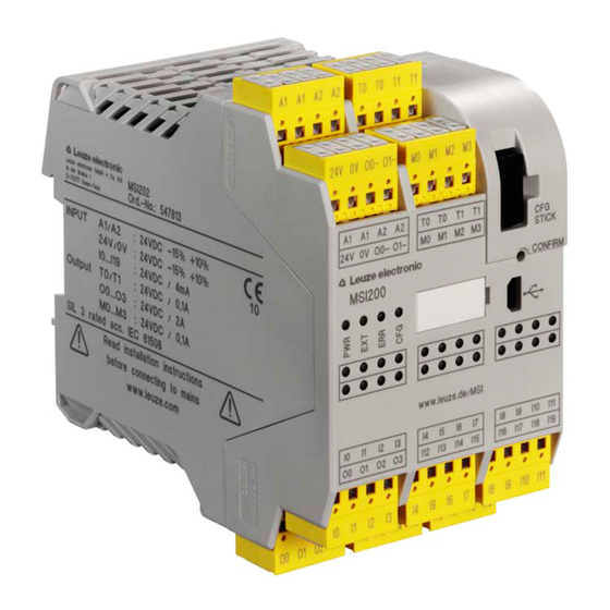
MSI 100 and MSI 200 Safety Modules
Product Description
Chapter 3
Figure 3-1 Screw Terminals (Left) and Spring-Cage Terminals (Right)
Figure 3-2 MSI 100 Block Diagram
Figure 3-3 MSI 200 Block Diagram
Connection of Extension Devices
Figure 3-4: Possible Operating Modes (Status) of MSI 100/200
Operating Modes (Status) of the Safety Modules
Operating and Indication Elements
Diagnostic and Status Indicators
Figure 3-5 MSI 100/200 Operating and Display Elements
Confirm Button
USB Interface
Figure 3-6 Status Line in the Msisafesoft Safe Configuration Software (Safety Module Al- Ready Contains a Configuration Project)
Ac-Msi-Cfg1
Figure 3-7 AC-MSI-CFG1 with MSI 100/200 Safety Module
Module Behavior in Case of Missing AC-MSI-CFG1
Signal Connections
Figure 3-8: Signal Connections MSI 100/200
Safe Inputs
Safe Outputs
Clock Outputs
Signal Outputs
Ground-Switching Outputs
Supply Connections
Figure 4-1: Screw Terminals (Left) and Spring-Cage Terminals (Right)
MSI-EM200-8I4IO Safe Extension Module
Product Description
Chapter 4
Diagnostic and Status Indicators
Figure 4-2 MSI-EM200-8I4IO Block Diagram
Figure 4-3 Diagnostic and Status Indicators MSI-EM200-8I4IO
Signal Connections
Figure 4-4 Signal Connections MSI-EM200-8I4IO
Safe Inputs
Safe Outputs
Clock/Signal Outputs
Supply Connections
Figure 5-1: Screw Terminals (Left) and Spring-Cage Terminals (Right)
MSI-EM200-4RO Safe Extension Module
Product Description
Chapter 5
Figure 5-2 MSI-EM200-4RO Block Diagram
Insulation Coordination
Diagnostic and Status Indicators
Figure 5-3 Diagnostic and Status Indicators MSI-EM200-4RO
Signal Connections
Figure 5-4 Signal Connections MSI-EM200-4RO
Relay Outputs
Safe Relay Outputs
Signal Outputs
Supply Connections
Information on the Wiring Examples
Single-Channel Assignment of the Safe Digital Inputs
Cross Circuit Monitoring Switched on
Chapter 6
Figure 6-1: Single-Channel Assignment of the Inputs
Wiring Examples
Cross Circuit Monitoring Switched Off, External Supply
Figure 6-2: Single-Channel Assignment of the Inputs: External Supply
External Supply (OSSD)
Figure 6-3 Single-Channel Assignment of the Inputs: External Supply (OSSD)
Two-Channel Equivalent Assignment of the Safe Digital Inputs
Cross Circuit Monitoring Switched On, Supplied by T0 and T1
Figure 6-4 Two-Channel Equivalent Assignment of the Inputs, Supplied by T0 and T1 (both Clocked)
Cross Circuit Monitoring Switched Off, External Supply
Figure 6-5 Two-Channel Equivalent Assignment of the Inputs, External Supply, Cross Cir- Cuit Monitoring Switched off
External Supply (OSSD)
Figure 6-6: Two-Channel Equivalent Assignment of the Inputs, External
Two-Channel Antivalent Assignment of the Safe Digital Inputs
Cross Circuit Monitoring Switched On, Supplied by T0 and T1
Figure 6-7 Two-Channel Antivalent Assignment of the Inputs, Supplied by T0 and T1, Cross Circuit Monitoring Switched on
Cross Circuit Monitoring Switched Off, External Supply
Figure 6-8 Two-Channel Antivalent Assignment of the Inputs, External Supply
Safe Digital Outputs
Figure 6-9 Example for the Freewheeling Circuit of an External Relay
Information on the Protective Circuitry of External Relays/Con- Tactors (Freewheeling Circuit)
Figure 6-10 Single-Channel Assignment of the Outputs
Single-Channel Assignment of the Safe Digital Outputs
Figure 6-11 Two-Channel Assignment of the Outputs
Two-Channel Assignment of the Safe Digital Outputs
Safe Relay Outputs
Figure 6-12 Example for the Freewheeling Circuit of an External Relay
Figure 6-13 Single-Channel Assignment of the Relay Outputs
Information on the Protective Circuitry of External Relays/Con- Tactors (Freewheeling Circuit)
Single-Channel Assignment of the Safe Relay Outputs
Figure 6-14 Two-Channel Assignment of the Relay Outputs
Single-Channel Assignment of the Safe Relay Outputs
Mounting, Removal and Electrical Installation
Safety Notices for Mounting, Removal and Electrical Installation
Mounting
Important Mounting Instructions
Mounting Instructions
Mounting Location
Mounting
Chapter 7
Figure 7-1: Mounting DIN Rail Connectors
Figure 7-2 Mounting a MSI 100/200 Module on the DIN Rail
Removal
Electrical Installation
Figure 7-3 Connecting to Screw Terminals
Figure 7-4 Connecting to Spring-Cage Terminals
Connecting Signal Lines
Connecting the Supply Voltage
Figure 7-5: Connecting the MSI 100/200 Supply Voltage
Figure 7-6: Connecting the Supply Voltage MSI-EM200-8I4IO and MSI-EM200-4RO
Example Connection of an MSI 100/200 System
Figure 7-7 MSI 100/200 System Voltage Supply
Firmware Update
Safety Notices for the Firmware Update
Requirement for Firmware Update
Running a Firmware Update
Installing Software
Msisafesoft Configuration Software
Figure 9-1 Opening the Help System in the Msisafesoft Configuration Software
Opening the Software Help System
Chapter 8 Chapter 9
Chapter 9
10 Configuration and Commissioning
Example for Configuration and Commissioning
Chapter 10
Figure 10-1 Flow Chart: Example Configuration and Commissioning (1 of 3)
Figure 10-2 Flow Chart: Example Configuration and Commissioning (2 of 3)
Figure 10-3 Flow Chart: Example Configuration and Commissioning (3 of 3)
Downloading Configuration from the Msisafesoft Configuration Software
Figure 10-4 USB Connection between PC and Safety Module
Figure 10-5 Dialog Box Following Successful Data Transmission
Figure 10-6 Confirming the Configuration with the "Confirm" Button
Loading the Configuration Using the AC-MSI-CFG1 Memory Module
Figure 10-7 Insert AC-MSI-CFG1
Uploading the Configuration from the Safety Module
Function Test
Performing Function Test with the Help of Online Mode
Figure 10-8: Example of a Function Test for the Safety System Using the Online
11 Diagnosis
Diagnosis Via LED Indicators on the Module
MSI 100 and MSI 200
Table 11-1: Diagnostic Indicators for MSI 100 and MSI 200
Table 11-2 Status Indicators of the Safe Inputs and Outputs for MSI 100 and MSI
Msi-Em200-8I4Io
Table 11-3 Diagnostic Indicators for MSI-EM200-8I4IO
Table 11-4 Status Indicators for MSI-EM200-8I4IO Safe Inputs and Outputs
Msi-Em200-4Ro
Table 11-5 Diagnostic Indicators for MSI-EM200-4RO
Table 11-6 Status Indicators of the Safe Outputs for MSI-EM200-4RO
12 Problems and Solutions
General
Table 12-1 Solutions for General Problems
Configuration Editor
Graphical Connection Editor
Table 12-2 Solutions for Problems with the Graphical Connection Editor
Table 12-3 Solutions for Problems with the Configuration Editor
Online Communication between Msisafesoft and the Safety Module
Table 12-4: Solutions for Communication Problems between Msisafesoft and the Safety
Communication between the Safety Module and the Safe Extension Module
Safety Module Messages
Table 12-5: Solutions for Communication Problems between Safety Module and Safe Ex
Table 12-6 Solutions for Messages from the Safety Module
13 Maintenance, Repair, Decommissioning and Disposal
Decommissioning and Disposal
Maintenance
Repair
14 Technical Data and Ordering Data
Technical Data MSI 100 and MSI 200
Chapter 11 Chapter 12 Chapter 13 Chapter 14
Chapter 12 Chapter 13 Chapter 14
Chapter 13 Chapter 14
Chapter 14
Figure 14-1: Derating Curve MSI 100 and MSI 200
Technical Data MSI-EM200-8I4IO
Figure 14-2: Derating Curve MSI-EM200-8I4IO
Technical Data MSI-EM200-4RO
Figure 14-3 Derating Curve MSI-EM200-4RO
Certifications
Conformity with EMC Directive
System Requirements for the Msisafesoft Configuration Software
Ordering Data
Accessories
Gateways
MSI 100/200 Modules
Software
Documentation
A Technical Appendix
Calculation of the Power Loss
A 2 Switch-Off Time of the MSI 100/200 System
Appendix A
Figure A-1 Switch-Off Time for the Safety Function
A 3 Use of MSI 100/200 Modules at Altitudes above 2000 M above Sea Level
Figure 14-4 Example of a Shifted Derating Curve (Red)
B List of Appendices
Figures
Tables
Index
C Revision History
Advertisement
Quick Links
1
Error Detection
Download this manual
MSI 100/200
Configurable safety modules and
safe extension modules
U S E R M A N U A L
Table of
Contents
Previous
Page
Next
Page
1
2
3
4
5
Advertisement
Chapters
Table of Contents
3
B List of Appendices
127
Table of Contents
Need help?
Do you have a question about the MSI 200 Series and is the answer not in the manual?
Ask a question
Questions and answers
Subscribe to Our Youtube Channel
Related Manuals for Leuze electronic MSI 200 Series
Control Unit Leuze electronic MSI 400 Series Original Operating Instructions
Main module of the modular safety controller msi 400 (33 pages)
Control Unit Leuze electronic MSI 100 Series User Manual
Configurable safety modules and safe extension modules (137 pages)
Control Unit Leuze electronic MSI-EM-IO84NP Series Original Operating Instructions
Extension module of the modular safety control msi 400 (22 pages)
Control Unit Leuze electronic MSI-EM-1084 Series Original Operating Instructions
Expansion modules of the configurable safety controller msi 400 (30 pages)
Control Unit Leuze electronic AC-CPB Quick Start Manual
Display and control units (2 pages)
This manual is also suitable for:
Msi-em200-4pro series
Msi101
Msi-em200-8i4io series
Msi 100 series
Msi201
Msi202
...
Show all
Msi102
Msi-em202-8i4io
Msi-em201-8i4io
Msi-em201-4pro
Msi-em202-4pro
Table of Contents
Save PDF
Print
Rename the bookmark
Delete bookmark?
Delete from my manuals?
Login
Sign In
OR
Sign in with Facebook
Sign in with Google
Upload manual
Upload from disk
Upload from URL


Need help?
Do you have a question about the MSI 200 Series and is the answer not in the manual?
Questions and answers