Sign In
Upload
Manuals
Brands
Comtech EF Data Manuals
Modem
DMD1050TS
Comtech EF Data DMD1050TS Modem Board Manuals
Manuals and User Guides for Comtech EF Data DMD1050TS Modem Board. We have
1
Comtech EF Data DMD1050TS Modem Board manual available for free PDF download: Installation And Operation Manual
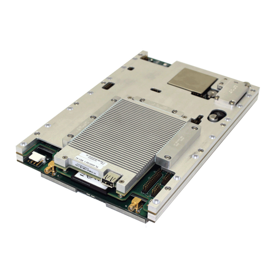
Comtech EF Data DMD1050TS Installation And Operation Manual (316 pages)
Satellite Modem Board
Brand:
Comtech EF Data
| Category:
Modem
| Size: 9 MB
Table of Contents
Table of Contents
3
List of Tables
12
About this Manual
19
Conventions and References
19
Patents and Trademarks
19
Related Documents
20
Military Standards
20
Warnings, Cautions, and Notes
20
Recommended Standard Designations
21
Preface
19
Comtech EF Data Headquarters
21
Product Support
21
Safety and Compliance
21
Operating Environment
21
Warranty Policy
22
Limitations of Warranty
22
Exclusive Remedies
23
Chapter 1. Introduction
25
Overview
25
Figure 1-1. DMD1050TS Satellite Board Modem (Top View)
25
DMD1050TS Configurations
26
Features/Options Installed at Time of Order
26
Feature Upgrades
26
Function Accessibility
26
Chapter 2. Installation
27
Unpacking and Inspection
27
Installation Requirements
28
Removal from Container and Assembly
28
Installation Considerations
28
Tools Required
29
Figure 2-1. Heat Path
29
DMD1050TS Initial Configuration Check
30
Standard DMD1050TS Factory Configuration Settings
30
Modulator Checkout
31
Initial Power-Up
31
M&C Web Browser Setup
31
M&C Terminal Setup
32
Storage
32
Chapter 3. Theory of Operation
33
DMD1050TS Hardware
33
Figure 3-1. DMD1050TS Block Diagram
33
L-Band Printed Circuit Card
34
Figure 3-2. L-Band Assembly
34
Baseband Processing Printed Circuit Card
35
Figure 3-3. DMD1050TS Baseband Processing Card Block Diagram
35
Fips 140 Level 2 TRANSEC Security Module
36
Figure 3-4. DMD1050TS FIPS 140 Level 2 TRANSEC Processing Module Block Diagram
37
DMD1050TS Functional Block Diagram
38
Baseband Processing
38
Tx Baseband Processing
38
Rx Baseband Processing
39
Figure 3-5. DMD1050TS Universal Satellite Modem Functional Block Diagram
39
Fips Module Processing
40
Monitor & Control (M&C)
41
Terminal Port/Es-ES Communications (J3)
41
Terminal Mode Control
41
Modem Terminal Mode Control
41
Modem Setup for Terminal Mode
42
Connect the Terminal
42
Terminal Screens
42
Modem Remote Communications (Radyne Link Level Protocol)
43
RLLP Protocol Structure
43
Modem Setup for Ethernet M&C (J11)
43
M&C Default/Reset Plug Settings (JP1 & JP2)
43
Ethernet Data Interface - (J10)
44
Table 3-1. DMD1050TS HDLC Interoperation
45
Figure 3-6. Point-To-Multipoint with Daisy Chaining
47
Internal Clock
49
Loopback Features (Terrestrial & IF)
49
Figure 3-7. Loopback Functional Block Diagram
50
Figure 3-8. Loopback Functional Block Diagram
51
Figure 3-9. Loopback Functional Block Diagram
51
DMD1050TS Clocking Options
52
Tx Clock Options
52
Figure 3-10. Clocking and Polarity Diagram
52
Rx Buffer Clock Options
53
Ethernet Data Interface
54
Reed-Solomon (R-S) Codec
55
R-S Operation in the DMD1050TS
55
R-S Code Rate
55
Interleaving
55
Figure 3-11. R-S Encoder Functional Block Diagram
55
Figure 3-12. R-S Decoder Functional Block Diagram
55
Table 3-2. R-S Codes
56
DMD1050TS Automatic Uplink Power Control (AUPC) Operation
57
Radyne AUPC
57
Ef Aupc
58
Near Side AUPC
58
Table 3-3. Local AUPC Functions
59
Table 3-4. Remote AUPC Functions (EF AUPC Only)
60
Asynchronous Overhead Operation (J3)
61
Table 3-5. Pin Assignments
62
Standard IBS ES-To-ES Mode
63
Enhanced Asynchronous Mode (Proprietary)
63
Table 3-6. IBS Standard
63
Satellite Control Channel (SCC) - J3
64
SCC Framing Structure
64
Aggregate Data Rate
65
Overhead Rate Comparison
66
Actual Overhead Rate Calculation
66
Table 3-7. SCC Overhead Rates
66
SCC Overhead Channel Setup
67
Table 3-8. SCC Overhead Chart Examples (Viterbi 3/4 W/V.35 Scrambler)
68
EBEM Framing Unit
69
EBEM Mode Set up on the DMD1050TS
69
DMD1050TS Information Throughput Adpatation (ITA)
69
Embedded Channel
69
STANAG Turbo Coding
70
FIPS TRANSEC Module
71
Traffic Encryption and Decryption Keys and Key Generation
71
Figure 3-13. Traffic Encryption Key Negotiation
72
Figure 3-14. Traffic Decryption Key Negotiation
73
DMD1050TS ID Codes (Feature Upgrades)
75
Strap Codes
75
Chapter 4. Rear Panel Interface
77
DMD1050TS Connections
77
Figure 4-1. DMD1050TS Front View
78
Figure 4-2. DMD1050TS Rear View
78
Figure 4-3. RF Board (PL-0021834)
79
Figure 4-4. Baseband Modem Board (PL-0022534)
80
Compact Flash (J6)
81
Power Input (J16)
81
BUC & LNB Power Input (J3)
81
Modem Connections (Standard)
81
Ext Ref (J9)
81
Table 4-1. DC Input Power Ports (J16)
81
Table 4-2. BUC & LNB DC Input Connector (J3)
81
TX L-Band if (J1)
82
RX L-Band if (J2)
82
ASYNC & Remote Port (J3) - 10-Pin Dual Row Header
82
Default/Shorting Plug (JP1 JP2) - 3 Pin Male Connector
82
Table 4-3. ASYNC & Remote Ports (J3)
82
Figure 4-5. Default/Shorting Plug (JP1 and JP2)
83
Table 4-4. Default/Reset Connections: 3-Pin Male Connector (JP1 & JP2)
83
Mil-188-114A (J4)
84
Ethernet M&C (J11)
84
Ethernet Data Interface (J10)
84
Table 4-5. MIL-188-114A Port (RS-422) 26-Pin Dual Row Header (J2)
84
Simple Key Loader (J17)
85
Antenna Handover (J18)
85
Table 4-6. DS-101 Simple Key Loader (J17)
85
Table 4-7. Antenna Handover (J18)
85
Chapter 5. Maintenance and Troubleshooting
87
Periodic Maintenance
87
Troubleshooting
87
Table 5-1. Symptoms and Possible Causes
87
Alarm Faults
88
Alarm Masks
90
Chapter 6. Technical Specifications
91
Data Rates Limits
91
Non-EBEM Modes
91
EBEM Modes
92
Non-DVB Modes
92
DVB Modes
94
Modulator
96
Demodulator
97
Plesiochronous Buffer
98
Monitor and Control
98
Terrestrial Interfaces
98
Environmental
98
Physical
98
BER Specifications
99
BER Performance (Viterbi)
99
Figure 6-1. B/0/QPSK BER Performance (Viterbi)
99
BER Performance (Sequential)
100
Figure 6-2. B/0/QPSK BER Performance (Sequential)
100
BER Performance (Viterbi - W/Reed-Solomon)
101
Figure 6-3. B/O/QPSK BER Performance (Viterbi - W/Rs)
101
BER Performance (8PSK Trellis)
102
Figure 6-4. 8PSK BER Performance (Trellis)
102
BER Performance (16QAM Viterbi)
103
Figure 6-5. 16QAM BER Performance (Viterbi)
103
BER Performance (16QAM Viterbi W/Reed-Solomon)
104
Figure 6-6. 16QAM BER Performance (Viterbi W/Rs)
104
BER Performance ((O)QPSK Turbo)
105
Figure 6-7. (O)QPSK BER Performance (Turbo)
105
BER Performance (BPSK Turbo)
106
Figure 6-8. BPSK BER Performance (Turbo)
106
BER Performance (8PSK Turbo)
107
Figure 6-9. 8PSK BER Performance (Turbo)
107
BER Performance (16QAM Turbo)
108
Figure 6-10. 16QAM BER Performance (Turbo)
108
B/O/QPSK BER Performance (LDPC)
109
Figure 6-11. B/O/QPSK BER Performance (LDPC)
109
8PSK/8QAM BER Performance (LDPC)
110
Figure 6-12. 8PSK/8QAM BER Performance (LDPC)
110
16QAM BER Performance (LDPC)
111
Figure 6-13. 16QAM BER Performance (LDPC)
111
BER Performance B/O/QPSK (MILSTD 188-165B or STANAG) Turbo
112
Figure 6-14. BER Performance B/O/QPSK (MILSTD 188-165B or STANAG) Turbo
112
BER Performance 8-PSK (MILSTD 188-165B or STANAG) Turbo
113
Figure 6-15. BER Performance 8-PSK (MILSTD 188-165B or STANAG) Turbo
113
BER Performance 16APSK (MILSTD 188-165B or STANAG) Turbo
114
Figure 6-16. BER Performance 16APSK (MILSTD 188-165B or STANAG)
114
Table 6-1. B/O/QPSK BER Performance (Viterbi)
115
Table 6-2. B/O/QPSK BER Performance (Sequential)
115
Table 6-3. B/O/QPSK BER Performance (Viterbi - W/Rs)
115
Table 6-4. 8PSK BER Performance (Trellis)
115
Table 6-5. 16QAM BER Performance (Viterbi)
115
Table 6-6. 16QAM BER Performance (Viterbi W/Rs)
116
Table 6-7. (O)QPSK BER Performancfe (Turbo)
116
Table 6-8. BPSK BER Performance (Turbo)
116
Table 6-9. 8PSK BER Performance (Turbo)
116
Table 6-10. 16QAM BER Performance (Turbo)
116
Table 6-11. B/O/QPSK BER Performance (LDPC)
117
Table 6-12. 8PSK / 8-QAM Rate BER Performance (LDPC)
117
Table 6-13. 16QAM BER Performance (LDPC)
117
Table 6-14. IBS/IDR Compliant Framing Modes
117
Table 6-15. B/O/QPSK BER Performance (MIL STD 188-165B or STANAG) Turbo
118
Table 6-16. 8PSK BER Performance (MIL STD 188-165B or STANAG) Turbo
118
Table 6-17. 16APSK BER Performance (MIL STD 188-165B or STANAG) Turbo
119
ACG Output Voltage
120
Figure 6-17. AGC Voltage Monitor
120
DMD Input Level Specification
121
Figure 6-18. DMD1050TS Input Level Specification
121
Chapter 7. Web Browser
123
Web Browser User Interface
123
Configuring Your PC
123
Graphical User Interface
123
Figure 7-1. Web User Interface Example
123
Screen Areas
124
Navigation
124
Light Emitting Diode (LED) Indicators
124
Figure 7-2. Navigation Tabs Example
124
Figure 7-3. Navigation Tabs Submenus Example
124
Figure 7-4. LED Example
124
Table 7-1. LED Indicators
125
Introduction Page
126
Figure 7-5. Introduction Page Example
126
Login Screen
127
Figure 7-6. Login Screen Example
127
Password Setup
128
Password Setup | Access Page
128
Figure 7-7. Password Setup | Access Page Example
128
Password Setup | Preferences Page
129
Figure 7-8. Password Setup | Preferences Page Example
129
IP Administration
130
IP Administration | Modem Addressing Page
130
Figure 7-9. IP Administration | Modem Addressing Page Example
130
IP Administration | Configure Apps Page
132
Figure 7-10. IP Administration | Configure Apps Page Example
132
Table 7-2. SNMP Parameters
134
Table 7-3. Web Parameters
134
Table 7-4. Terminal and Remote Port Parameters
135
IP Administration | Configure PC Page
136
Figure 7-11. IP Administration | Configure PC Page Example
136
Monitor and Control Menu
137
Transmit Menu
137
Figure 7-12. Transmit | General | if Page Example
137
Table 7-5. Network Specifications
139
Figure 7-13. Transmit | Data Page Example
140
Figure 7-14. Transmit | Reed-Solomon Page Example
144
Receive Menu
152
Table 7-6. Network Specifications
154
Interface Menu
164
Monitor Menu
169
System Menu
186
Test Menu
191
TRANSEC Module HTTP Interface
195
Chapter 8. Transec Module Https Interface
197
TRANSEC Module Overview
197
TRANSEC Module HTTPS Interface
197
Open the TRANSEC Module HTTPS Interface
197
Interface Instructions for Older Browsers
199
HTTPS Interface Menu Tree
199
TRANSEC Module HTTPS Interface
200
Configure
200
Monitor
206
Log
208
Table 8-1. Event Log Message Types
209
Firmware
210
Upload
211
TRANSEC Module Update Procedure
212
Chapter 9. Transec Module Ssh Cli Operation
217
Overview
217
SSH User Access
217
Command Line Interface (CLI)
219
CLI Menu System - Parallel Functionality
219
CLI Menu - Common Information, Navigation, Operation Features
219
Main Menu
220
Configuration Menu [C]
221
Table 9-1. CLI Submenus
221
Table 9-2. Configuration Menu Options
222
Table 9-3. Active Encryption Key Menu Options
223
Table 9-4. Future Encryption Key Menu Options
224
Table 9-5. Encryption Menu Options
225
Table 9-6. Network Menu Options
226
Table 9-7. Credentials Menu Options
227
Table 9-8. SSH Console Menu Options
228
Module Status Screen [M]
229
Event Log Menu [E]
230
Table 9-9. Event Log Menu Options
230
Unit Info Menu [ I ]
231
Table 9-10. Unit Information Options
231
Comtech EF Data Information Screen [Z]
232
Appendix A. Product Options
233
Hardware Options
233
Customized Options
233
Appendix B. Carrier Control
235
States
235
Carrier off
235
Carrier on
235
Carrier Auto
235
Carrier Vsat
235
Carrier Request to Send (RTS
236
Appendix C. Tcp/Ip Ethernet Setup
237
Introduction
237
TCP/IP Network Configuration
237
Boot Mode Submenu
237
Boot Server Tag Submenu
238
Modem Host Submenu
238
IP Address Mask Submenu
238
Modem IP Address Submenu
239
Server IP Address Submenu
239
Router IP Address Submenu
239
Modem Ethernet Address Submenu
239
Ethernet Rate Submenu
239
Network Configuration Summary
240
Ethernet Test
241
Connect the Modem Ethernet Cable to a Network Link
241
Connect the Modem Ethernet Cable Directly to a Computer (Without a Network
241
Test the Ethernet Connection Using the Ping Command (Optional
244
Appendix D. Web Browser Setup Guide
247
Introduction
247
Required Items
247
Web Interface Setup Guidelines
247
Prepare the DMD1050TS for Web Setup
247
IP Network Change from the Initial Web Setup
251
Configure the Modem
251
Configure the Computer
252
Web Users Setup and Configuration Control Options
253
Change the Password
254
Boot Mode Options (Reference Only
255
Appendix E. User Interface Connections
257
User Interface Connections
257
Connector Kit Part Numbers
257
J3 & J4 Interface Connectors Located on PCB
257
J3 & J4 Information on Supplied Interface Connectors
257
J3 & J16 Information on Supplied Interface Connectors for DC & BUC Power
258
Part Number Active08-56-0106
258
Part Details
258
Appendix F. Ethernet Data Interface
259
Introduction
259
Point-To-Point Applications
259
Transparent Operation
260
Point-To-Multipoint Applications
261
High Speed Mesh Applications
262
Low Speed Mesh Applications
263
Remote Monitor and Control Via SNMP
264
Enhanced Quality of Service (Qos
265
Normal Qos
265
Port Based Qos
265
Fair Weighted Queuing
266
Strict Priority Queuing
266
Satellite Packet Error Checking
266
Automatic Learning and Aging
266
Internal Buffer and Throttle
267
Any Data Rate, Modulation Type, FEC or Application
267
Appendix G. Strap Codes
269
Introduction
269
Table G-1. Strap Codes (Dis = Disable
269
Appendix H. Software Upgrade Procedure
273
Software Upgrade Procedure
273
Terminal Software Upgrade
273
Required Equipment
273
Upgrade Procedure
273
Purchase the Upgrades
273
Enter the Upgrade Code
274
Demonstration Procedure
275
Find the Available Features
275
Find the Unit ID
275
Request a Demonstration
275
Enter the Demonstration Code
275
Cancel Demonstration Mode
276
Cancel a Demonstration Mode
276
Web Browser Software Upgrade
276
Monitor and Control
276
Appendix I. Information Throughput Adaptation (Ita) Operation
279
Information Throughput Adaptation (ITA) Operation
279
Properties of ITA on the DMD1050TS
279
Basic Setup (Example
280
Table I-1. ITA Waveforms and Selection
280
Table I-2. Initial Modem Setup
281
Advertisement
Advertisement
Related Products
Comtech EF Data DMD-2050E
Comtech EF Data DMD50
Comtech EF Data Radyne DMD1050
Comtech EF Data Radyne DM240XR
Comtech EF Data DT-4572
Comtech EF Data DST
Comtech EF Data DT-4503
Comtech EF Data DT-4503/C
Comtech EF Data DT-4510
Comtech EF Data DT-4513
Comtech EF Data Categories
Modem
Switch
Amplifier
Network Router
Media Converter
More Comtech EF Data Manuals
Login
Sign In
OR
Sign in with Facebook
Sign in with Google
Upload manual
Upload from disk
Upload from URL