Table of Contents
Advertisement
Available languages
Available languages
Quick Links
Advertisement
Chapters
Table of Contents

Related Manuals for MICRO-EPSILON combiSensor KSH5


Summary of Contents for MICRO-EPSILON combiSensor KSH5
- Page 1 Betriebsanleitung Instruction Manual combiSENSOR KSH5 KSS6380...
- Page 2 MICRO-EPSILON MESSTECHNIK GmbH & Co. KG Königbacher Strasse 15 D-94496 Ortenburg Tel. 08542/168-0 Fax 08542/168-90 e-mail info@micro-epsilon.de www.micro-epsilon.de Zertifiziert nach DIN EN ISO 9001: 2008 Certified acc. to DIN EN ISO 9001: 2008...
-
Page 3: Table Of Contents
Inhalt Sicherheit ............................ 5 Verwendete Zeichen ......................... 5 Warnhinweise ........................... 5 Hinweise zur CE-Kennzeichnung ..................... 5 Bestimmungsgemäße Verwendung ....................6 Bestimmungsgemäßes Umfeld ......................6 Funktionsprinzip, Optionen, Technische Daten ................ 7 Messprinzip ............................7 2.1.1 Kapazitives Messverfahren ....................... 7 2.1.2 Wirbelstrom Messverfahren ......................7 2.1.3 Dickenbestimmung .......................... - Page 4 Betrieb und Wartung ........................ 26 Haftung für Sachmängel ......................26 Außerbetriebnahme, Entsorgung .................... 27 Anhang ............................27 Werkseinstellungen ........................27 combiSENSOR...
-
Page 5: Sicherheit
2004/108/EG „Elektromagnetische Verträglichkeit“ und die dort aufgeführten harmoni- sierten europäischen Normen (EN). Die EU-Konformitätserklärung wird gemäß der EU- Richtlinie, Artikel 10, für die zuständige Behörde zur Verfügung gehalten bei MICRO-EPSILON MESSTECHNIK GmbH & Co. KG Königbacher Straße 15 94496 Ortenburg Das Mess-System ist ausgelegt für den Einsatz im Industriebereich und erfüllt die An-... -
Page 6: Bestimmungsgemäße Verwendung
Sicherheit Bestimmungsgemäße Verwendung - Das Messsystem combiSENSOR ist für den Einsatz im Industriebereich konzipiert. - Es wird eingesetzt zur ƒ berührungslosen Dickenmessung von Kunststoff-Folien. ƒ berührungslosen Schichtdickenmessung von Isolatormaterialien. - Betreiben Sie das Messsystem nur innerhalb der technischen Daten angegebenen Werte, siehe Kap. -
Page 7: Funktionsprinzip, Optionen, Technische Daten
Funktionsprinzip, Optionen, Technische Daten Funktionsprinzip, Optionen, Technische Daten Messprinzip Der Aufbau von Messspule und Messelektroden ist konzentrisch. Damit messen bei- de gegen dieselbe Messobjektfläche. Das Signal des kapazitiven Wegsensors ist eine Funktion von Grundabstand, Isolatordicke und e . Gleichzeitig misst der Wirbelstrom- wegsensor den Abstand zur Gegenelektrode (zum Beispiel ebenes Blech oder zu einer hinter der Folie positionierten Metallwalze). -
Page 8: Dickenbestimmung
Funktionsprinzip, Optionen, Technische Daten 2.1.3 Dickenbestimmung Haupteinsatzgebiet des combiSENSORs ist die traversierende Dickenmessung von Kunststoff-Folien oder die Dicke von Kunststoff-Beschichtungen auf Metallplatten. Durch eine arithmetische Verknüpfung der beiden Sensorsignale werden mechanische Verän- derungen, zum Beispiel thermische Ausdehnungen, Durchbiegungen, Unrundheit der Messvorrichtung, kompensiert. -
Page 9: Aufbau Des Kompletten Messsystems
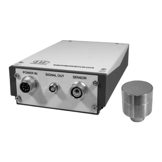
Funktionsprinzip, Optionen, Technische Daten Aufbau des kompletten Messsystems Das in ein Aluminiumgehäuse eingebaute, berührungslos arbeitende Messsystem, siehe Abb. 3, setzt sich zusammen aus: - Sensor KSH5 mit Sensorkabel, - Controller KSS6380 Abb. 3 Einkanal-Messsystem 2.2.1 Sensor Der combiSENSOR vereint im Sensorgehäuse einen Wirbelstrom-Wegsensor und einen kapazitiven Wegsensor. -
Page 10: Kss6380 Controller
Funktionsprinzip, Optionen, Technische Daten 2.2.3 KSS6380 Controller Der Controller vereint in einem Gehäuse den Oszillator und die Auswerteelektronik für den Sensor. Der kapazitive Anteil und Wirbelstromanteil im Sensor sind miteinander synchronisiert. Power Analog Sensor Ethernet supply output LED-Anzeigen Grün Messobjekt innerhalb des Messbereiches Messobjekt außerhalb des Messbereiches Der Controller ist bereits werkseitig auf den mitgelieferten Sensor mit Anschlusskabel abgestimmt. -
Page 11: Technische Daten
Funktionsprinzip, Optionen, Technische Daten Technische Daten Sensor KSH5 Messbereich 5 mm (max. Grundabstand) Messobjektdicke Isolator max. 2 mm Min. Durchmesser Messfläche 45 mm Gegenelektrode Fläche gerade oder min. Durchmesser 200 mm Linearität ±0,05 % ±2,5 µm bei Grundabstand 2,5 mm bei Grundabstand 4,5 mm Auflösung 0,32 µm... -
Page 12: Lieferung
Lieferung Lieferung Lieferumfang 1 Controller KSS6380 1 Sensor 1 Sensorkabel 1 Betriebsanleitung 1 8-polige Kabelbuchse für Stromversorgung 1 5-poligen Kabelstecker für Signalausgang 1 Netzwerkkabel (Crossover-Kabel) 1 CD mit Runtimeversion/MEDAQ-LIB (Ethernet) Nehmen Sie die Teile des Messsystems vorsichtig aus der Verpackung und trans- portieren Sie sie so weiter, dass keine Beschädigungen auftreten können. -
Page 13: Installation Und Montage
Installation und Montage Installation und Montage Vorsichtsmaßnahmen Auf den Kabelmantel des Sensorkabels dürfen keine scharfkantigen oder schweren Gegen- stände einwirken. In Bereichen mit erhöhtem Druck ist das Kabel grundsätzlich vor Druckbelastung zu schüt- zen. Der minimale Biegeradius beträgt 20 mm. Knicke müssen auf jeden Fall vermieden werden. Die Steckverbindungen sind auf festen Sitz zu prüfen. -
Page 14: Sensorkabel
Installation und Montage Sensorkabel Das Sensorkabel verbindet den Sensor mit dem Controller. Verbinden Sie den Sensor mit dem Controller über das mitgelieferte Sensorkabel. Der Anschluss erfolgt durch einfaches Stecken. Die Steckverbindung verriegelt selbst- ständig. Der feste Sitz kann durch Ziehen am Steckergehäuse (Kabelbuchse) geprüft werden. -
Page 15: Anschlussbelegung
Installation und Montage Anschlussbelegung 4.5.1 Spannungsversorgung Die Spannungsversorgung erfolgt über den 8-poligen Einbaustecker (DIN 45326). Pin- Belegung siehe Zeichnung und Tabelle. Dem Controller liegt eine 8-polige Kabelbuchse für die anwenderseitige Konfektionierung eines eigenen Anschlusskabels bei. Belegung 0 Volt +9 ... 36 Volt ( ca. 0,25 A bei 24 V) Lötstiftseite Kabelbuchse PC3/8 ist ein 3 m langes, fertig konfektioniertes 8-adriges Versorgungskabel. -
Page 16: Bedienung
Bedienung Bedienung Inbetriebnahme Bevor Sie den Controller an die Stromversorgung anschließen und diese einschalten, sind die Anzeige-/Ausgabegeräte über die 5-polige Signalausgangsbuchse anzuschlie- ßen, siehe Kap. 4.5.2. Bevor eine Messung oder Kalibrierung durchgeführt wird, benötigt das Messsystem eine Einlaufzeit von circa 30 Minuten. Bedien- und Anzeigeelemente Die Bedienung erfolgt ausschließlich über die Ethernetschnittstelle, siehe Kap. -
Page 17: Ethernetschnittstelle
über die Ethernetschnittstelle auslesen. Verwenden Sie dazu die beiliegende Runtimeversion auf CD-ROM, siehe Kap. 6.5, oder ein eigenes Programm. Micro-Epsilon unterstützt Sie mit dem Treiber MEDAQLib, der alle Befehle für den Controller KSS6380 enthält. Nähere Hinweise finden Sie auf der beiliegenden CD oder im Internet unter www.micro-epsilon.de/software “Standardappli-... - Page 18 Ethernetschnittstelle Wählen Sie „Internet Protocol (TCP/IP) > Eigenschaften“ Die IP-Adresse des Controllers ist werkseitig auf 192.168.0.2 und der Port auf 10001 eingestellt. Dies kann jedoch jederzeit geändert werden: - mittels Webbrowser. Geben Sie die aktuelle IP-Adresse in die Adresszeile ein. Quittie- ren Sie den Authentifizierungsdialog mit “OK“.
-
Page 19: Datenformat Der Messwerte
Ethernetschnittstelle Datenformat der Messwerte Ein Messwert setzt sich aus 4 aufeinander folgenden Bytes zusammen: Bit 1 Bit 2 Bit 3 Bit 4 Bit 5 Bit 6 Bit 7 Bit 8 1. Byte 1 (Start) Kanalnummer ( 0 ... 3 ) Vz-Bit MSB 2. -
Page 20: Befehle
Ethernetschnittstelle Befehle Sobald ein $ Zeichen empfangen wird, sendet der Controller keine Messwerte mehr. Der Controller gibt alle gesendeten Zeichen sofort als Echo zurück. Nachdem die Antwort gesendet wurde, beginnt der Controller wieder, Messwerte zu senden (gilt für die Betriebsart Dauersenden). Befehle werden im ASCII-Format übertragen. -
Page 21: Mittelungsart (Avt = Averaging Type)
Ethernetschnittstelle 6.4.4 Mittelungsart (AVT = Averaging Type) Art der Messwertmittelung Befehl $AVTn<CR> Antwort $AVTnOK<CRLF> Index n = 0: Keine Mittelwertbildung (Standardeinstellung) n = 1: Gleitender Mittelwert ? = Abfrage Mittelungsart Abfrage Mittelungsart Befehl $AVT?<CR> Antwort $AVT?nOK<CRLF> 6.4.5 Mittelungszahl (AVN = Averaging Number) Anzahl der Messwerte, über die eine Mittelung berechnet wird (einstellbar von 2 …... -
Page 22: Einstellungen Speichern (Ssu = Save Setup)
Ethernetschnittstelle 6.4.10 Einstellungen speichern (SSU = Save Setup) Speichert alle Einstellungen im EEPROM. Werden Einstellungen nicht gespeichert, so werden nach dem nächsten Neustart des Controllers die alten Werte aus dem EEPROM wieder verwendet. Befehl $SSU<CR> Antwort $SSUOK<CRLF> 6.4.11 Einstellungen laden (RSU = Read Setup) Lädt alle Einstellungen aus dem EEPROM. -
Page 23: Mathematikfunktion Abfragen (Gmf = Get Mathematic Function)
Ethernetschnittstelle - Es ist nicht möglich eine Mathematikfunktion auf den Kanal des Temperatursignals zu setzen. 6.4.14 Mathematikfunktion abfragen (GMF = Get Mathematic Function) Liest die Mathematikfunktion eines Kanals aus. Befehl $GMFm<CRLF> Antwort $GMFm:Offset,FaktorCapa,FaktorEddyOK<CLRF> Index m: 1 ... 3 Kanalnummer der Mathematikfunktion (1= Diffe- (Kanalnummer) renz-Kanal, 2= Capa-Kanal, 3= Eddy-Kanal) Offset... -
Page 24: Runtimeversion
Ethernetschnittstelle Runtimeversion Dem KSS6380 liegt eine ICONNECT-Runtimeversion zur Konfiguration des Controllers, sowie zum Auslesen und Speichern der Messwerte bei. Die wichtigsten Bedienelemente sind im Folgenden kurz erläutert: 1: IP-Adresse des Controllers (KSS6380) 2: Datenrate der Messwerte 3: Öffnet einen Dialog zum Skalieren der Plots. Wählen Sie zwischen vollem Messbe- reich, benutzerdefiniertem Messbereich und automatischer Skalierung. - Page 25 Ethernetschnittstelle Unter „Channel“ wird der Kanal ausgewählt, der mit der Mathematikfunktion belegt werden soll. Es kann auch das Rohsignal des Kanals mit verrechnet werden. Übertragen wird jedoch nur der errechnete Wert. combiSENSOR Seite 25...
-
Page 26: Betrieb Und Wartung
Die Haftung für Sachmängel beträgt 12 Monate. Innerhalb dieses Zeitraums werden fehlerhafte Teile, ausgenommen Verschleißteile, kostenlos instandgesetzt oder ausge- tauscht, wenn das Gerät kostenfrei an MICRO-EPSILON eingeschickt wird. Nicht unter die Haftung für Sachmängel fallen solche Schäden, die durch unsachgemä- ße Behandlung oder Gewalteinwirkung entstanden oder auf Reparaturen oder Verände-... -
Page 27: Außerbetriebnahme, Entsorgung
Außerbetriebnahme, Entsorgung Außerbetriebnahme, Entsorgung Entfernen Sie das Versorgungskabel am Controller. Entfernen Sie das Sensorkabel zwischen Sensor und Controller. Das System ist entsprechend der Richtlinie 2002/95/EG, „RoHS“, gefertigt. Die Entsor- gung ist entsprechend den gesetzlichen Bestimmungen durchzuführen (siehe Richtlinie 2002/96/EG). Anhang Zubehör und Ersatzteile PC3/8 8-adriges Versorgungskabel mit Kabelbuchse DIN 45326, Länge 3 m... - Page 28 Contents Safety ............................29 Symbols Used ..........................29 Warnings ............................29 Notes on CE Identification ......................29 Proper Use ............................30 Proper Environment ........................30 Functional Principle, Technical Data ..................31 Measuring Principle ........................31 2.1.1 Capacitive Principle ........................31 2.1.2 Eddy Current Principle ........................
-
Page 29: Safety
2004/108/EC ‘Electromagnetic Compatibility’ and the European standards (EN) listed ther- ein. The EC declaration of conformity is kept available according to EC regulation, article 10 by the authorities responsible at MICRO-EPSILON MESSTECHNIK GmbH & Co. KG Koenigbacher Straße 15 D-94496 Ortenburg... -
Page 30: Proper Use
Safety Proper Use - The system is designed for use in industrial areas. - It is used ƒ for measuring film thickness of plastics ƒ for measuring layer thickness of insulators - The sensors may only be operated within the limits specified in the technical data, see Chap. -
Page 31: Functional Principle, Technical Data
Functional Principle, Technical Data Functional Principle, Technical Data Measuring Principle The construction of the measurement coil and measurement electrodes is concentric. Both therefore measure against the same target (measuring object). The signal of the capaciti- ve displacement sensor is a function of the offset, the thickness of the insulator and e . -
Page 32: Thickness Measurement
Functional Principle, Technical Data 2.1.3 Thickness Measurement The main field of application is the traversing thickness measurement of plastic film or of plastic coating on metal plates. Arithmetical coupling of the two sensor signals provides compensation of mechanical changes, for example thermal expansion, deflections, eccentri- city in the measurement device. -
Page 33: Structure
Functional Principle, Technical Data Structure The non-contact, single-channel measuring system, see Fig. 3, installed in aluminium housings, consists of: - a KSH5 sensor with sensor cable, - a KSS6380 controller. Fig. 3 Single-channel measuring system 2.2.1 Sensor In its sensor housing the combiSENSOR combines an eddy current displacement sensor and a capacitive displacement sensor. -
Page 34: Kss6380 Controller
Functional Principle, Technical Data 2.2.3 KSS6380 Controller The controller contains an oscillator and a signal conditioning electronics for the sensor. The capacitive and eddy current part of the sensor are synchronized with each other. Legend mm (inches) Power Analog Sensor Ethernet supply output... -
Page 35: Technical Data
Functional Principle, Technical Data Technical Data Sensor KSH5 Measuring range (max. offset) 5 mm (.20) Insulator thickness 2 mm max. (.08) Min. diameter target 45 mm (1.77) Ground electrode Even surface or min. diameter 200 mm (7.88) Linearity ±0.05 % ±2.5 µm with start of measuring range with start of measuring range... -
Page 36: Delivery
Delivery Delivery Unpacking - 1 controller KSS6380 - 1 Sensor - 1 Sensor cable - 1 Instruction manual - 1 8-pole female cable socket for power - 1 5-pole male cable socket for analog signals - 1 network cable (crossover cable) - 1 CD with Runtime-version/MEDAQ-LIB (Ethernet) Remove the parts of the system carefully from the packaging and transport them in such a way that they are not damaged. -
Page 37: Installation And Assembly
Installation and Assembly Installation and Assembly Precautionary Measures No sharp-edged or heavy objects may come into contact with the sensor cable sheath. In pressurised rooms the cable must be protected against pressure loads. The minimum bending radius is 20 mm (.79 inch). Kinks must be avoided at all cost. The connections must be checked for tight fit. -
Page 38: Sensor Cable
Installation and Assembly Sensor Cable The sensor cable connects the sensor with the controller. Connect the sensor to the controller by the sensor cable. The connection is made by simple plugging. The connector locks automatically. The tight fit can be checked by pulling the connector housing (cable bushing). A damaged cable cannot be repaired. -
Page 39: Pin Assignment
Installation and Assembly Pin Assignment 4.5.1 Power Supply The power supply is connected by the 8-pin built-in male connector (DlN 45326). See the drawing and table for the pin assignment. The controller contains a 8-pin female cable so- cket for the user-side assembly of your own connecting cable. Assignment 0 Volt +9 ... -
Page 40: Operation
Operation Operation Starting Up The display/output devices must be connected through the 5-pin signal output socket, see Chap. 4.5.2, before connecting the controller to the power supply and switching on the power supply. The measurement equipment should warm up for about 30 minutes before a measure- ment or calibration is carried out. -
Page 41: Ethernet Interface
For that purpose, use the enclosed runtime version on CD-ROM, see 6.5, or use your own program. Micro-Epsilon supports the MEDAQLib driver that includes all commands for the controller KSS6380. You will find more details on the enclosed CD or on the Internet: www. - Page 42 Ethernet Interface Select “Internet Protocol (TCP/IP) > Properties“ By default, the IP address of the controller is set to 192.168.0.2 and the port on 10001. This can be changed at any time: - by using the web browser. Enter the current IP address into the address bar. Confirm the authentification dialog by pressing “OK“.
-
Page 43: Data Format Of Measuring Values
Ethernet Interface Data Format of Measuring Values The measuring value is made up of 4 consecutive bytes: Bit 1 Bit 2 Bit 3 Bit 4 Bit 5 Bit 6 Bit 7 Bit 8 1. Byte 1 (Start) Channel number ( 0 ... 3 ) Vz-Bit MSB 2. -
Page 44: Commands
Ethernet Interface Commands As soon as a $ character has been received, the controller will no longer transmit measure- ment values. The controller immediately returns all transmitted characters back as echo. After the response has been sent, the controller starts to send measurements again (applies to the operating mode ”continuous transmission”). -
Page 45: Averaging Type (Avt)
Ethernet Interface 6.4.4 Averaging Type (AVT) Mode of measurement averaging Command $AVTn<CR> Response $AVTnOK<CRLF> Index n = 0: No averaging (Default setting) n = 1: Moving average ? = Request averaging type Request averaging type Command $AVT?<CR> Response $AVT?nOK<CRLF> 6.4.5 Averaging Number (AVN) Number of measuring values used to calculate the average (adjustable from 2 ... -
Page 46: Save Setup (Ssu)
Ethernet Interface 6.4.10 Save Setup (SSU) Saves all settings in EEPROM. If settings are not saved, the old values from the EEPROM are reused after the next restart of the controller. Command $SSU<CR> Response $SSUOK<CRLF> 6.4.11 Read Setup (RSU) Reads all settings from the EEPROM. Command $RSU<CR>... -
Page 47: Get Mathematic Function (Gmf)
Ethernet Interface 6.4.14 Get Mathematic Function (GMF) Evaluates the mathematic function of a channel. Command $GMFm<CRLF> Response $GMFm:Offset,FactorCapa,FactorEddyOK<CLRF> Index m: 1 ... 3 Channel number of the mathematic function (Channel number) (1= difference channel, 2= Capa channel, 3= Eddy channel) Offset 24 bit offset value with sign in hex format, whereby 21 bit correspond to 100 % of the measurement... -
Page 48: Runtimeversion
Ethernet Interface Runtimeversion The KSS6380 is accompanied by an ICONNECT runtime version for the configuration of the controller as well as for the readout and saving of the measuring values. The following briefly explains the most important control elements: 1: IP address of the controller (KSS6380) 2: Data rate of the measuring values 3: Opens a dialog for the scaling of the plots. - Page 49 Ethernet Interface The channel which can be assigned by the mathematic function is selected under “Chan- nel”. The raw signal of the channel can be evaluated, too. However, only the evaluated value is transferred. combiSENSOR Page 49...
-
Page 50: Operation And Maintenance
The terms of the purchasing contract apply in full. MICRO-EPSILON will specifically not be responsible for any consequential damage. MICRO-EPSILON always strives to supply customers with the finest and most advanced equipment. Development and refinement is therefore performed continuously and the right for design changes without prior notice is accordingly reserved. -
Page 51: Decommissioning, Disposal
Decommissioning, Disposal Decommissioning, Disposal Disconnect the power supply and output cables on the controller. Disconnect the sensor cable between sensor and controller. The system is produced according to the directive 2002/95/EC („RoHS“). The disposal is done according to the legal regulations (see directive 2002/96/EC). Appendix Accessories and Spare Parts PC3/8... - Page 52 MICRO-EPSILON MESSTECHNIK GmbH & Co. KG X975X225-A021100HDR Königbacher Str. 15 · 94496 Ortenburg / Deutschland Tel. +49 (0) 8542 / 168-0 · Fax +49 (0) 8542 / 168-90 *X975X225-A02* info@micro-epsilon.de · www.micro-epsilon.de...
Need help?
Do you have a question about the combiSensor KSH5 and is the answer not in the manual?
Questions and answers