Table of Contents
Advertisement
Quick Links
Advertisement
Table of Contents

Related Manuals for mru SWG100 BIOEX


Summary of Contents for mru SWG100 BIOEX
- Page 1 SWG100BIO Ex. User Manual MRU GmbH, D-74172 Neckarsulm 1 / 108...
- Page 2 SWG100 BIOGAS User Manual 2 / 108 MRU GmbH, D-74172 Neckarsulm...
-
Page 3: Table Of Contents
11.3. Packing ........................9 11.4. Return of hazardous waste ..................9 11.5. Return of analyzer ...................... 9 11.6. MRU guarantee conditions..................10 12. Analyzer Description ...................... 11 12.1. Intended use ......................11 12.2. Principle of operation ....................12 12.3. Marking and range of application ................13 12.4. - Page 4 28. Defined registers to be read by the master ..............101 28.1. Analyser Status (address 0 and some mirror addresses) ........104 28.2. Analyser System Alarm (address 2 and some mirror addresses) ......105 28.3. Spare parts list ....................... 106 4 / 108 MRU GmbH, D-74172 Neckarsulm...
- Page 5 Packing List and have it signed by the shipper’s agent prior to accepting the shipment. Submit damage claim to MRU immediately. NOTE: Damage claims not received by MRU within 3 days of receipt of shipment will not be accepted. The products described in this manual are subject to continuous development and improvement and it is therefore acknowledged that this manual may contain errors or omissions.
-
Page 6: General Information
These should be clarified with the manufacturer (MRU). Any additional protective measures for outdoor mounting have to be provided by the plant operator. The manufacturer (MRU) is supporting the plant operator in choosing appropriate protective measures. 1.2. Installation instructions Installation instructions, which are described in chapter 17 of the operation manual, have to be strictly carried out. -
Page 7: Important Information About The User's Operation Manual
Analyzers is continuously sampling a certain volume (approx 50l/h) of the sample gas, and is venting it to ambient air. For this reason, there are two aspects which must be considered: toxicity danger of sample gas MRU GmbH, D-74172 Neckarsulm 7 / 108... - Page 8 Only trained personnel should carry out installation of stationary instrument and/or maintenance, service and repair. Opening the stationary analyzer cabinet can expose personnel to injuries and shocks from mains voltage! 8 / 108 MRU GmbH, D-74172 Neckarsulm...
-
Page 9: Packing
11.3. Packing Packing regulation of 12.07.1991 If your local waste facility does not accept MRU packing materials for disposal, you may return it to MRU or our local sales representative. Packing materials returned to MRU must be returned prepaid. 11.4. -
Page 10: Mru Guarantee Conditions
7. The service of a guarantee conditions will not enlarge the guarantee time. Demands because of consequential damages are excluded. 8. The transport costs for round trip takes the consignor or the warrantee. 9. MRU reserves the right, to determine individual conditions or exceptions. These will be separated informed. 10 / 108... -
Page 11: Analyzer Description
All sample points are equipped with a flow restrictor orifice, which allows also sampling the gas from the higher-pressure gas pipe of the engine, while limiting the maximum amount of gas in case of internal cabinet piping leakage. MRU GmbH, D-74172 Neckarsulm 11 / 108... -
Page 12: Principle Of Operation
(several years) but may be easily replaced once the end-of-life is reached. In regular time intervals (user settable), the instrument automatically switches to purge • the sensors with fresh (ambient) air for re-adjust the zero point. 12 / 108 MRU GmbH, D-74172 Neckarsulm... -
Page 13: Marking And Range Of Application
Module with 4 channel analog outputs/inputs 4-20mA, with 2x “fail safe” alarm relays • Converter module of RS485 into Profibus • Cabinet heater for freeze protection Ask our sales representatives for available options and accessories or check out our MRU website. MRU GmbH, D-74172 Neckarsulm 13 / 108... -
Page 14: Overview Of The Swg-100Bio Ex
Power supply lines and signal lines Cable for power supply: Cable type: H 07 RN-F 5 G 0,75 mm² • Signal lines for 4…20 mA analog outputs. • Signal lines for Modbus RTU digital transfer. • 14 / 108 MRU GmbH, D-74172 Neckarsulm... -
Page 15: Dimensions And Views Of The Analyser
4. Condensate outlet G1/8 inch female thread Bottom view Reference: 1. Cable gland M16 for power supply 2. PE bolt for earthing cable 3. Cable gland M16 for I/O modules 4. Breather drain MRU GmbH, D-74172 Neckarsulm 15 / 108... -
Page 16: Position Of The Gas In And Outlets
Inlet cable gland M16 for mains power supply Heat sink for gas cooler unit Condensate outlet port, female G1/8” thread Zero gas inlet port, female G1/8” thread Calibration gas inlet port, female G1/8” thread Vent outlet port, female G1/4” thread 16 / 108 MRU GmbH, D-74172 Neckarsulm... -
Page 17: Operating Unit: Display And Keypad
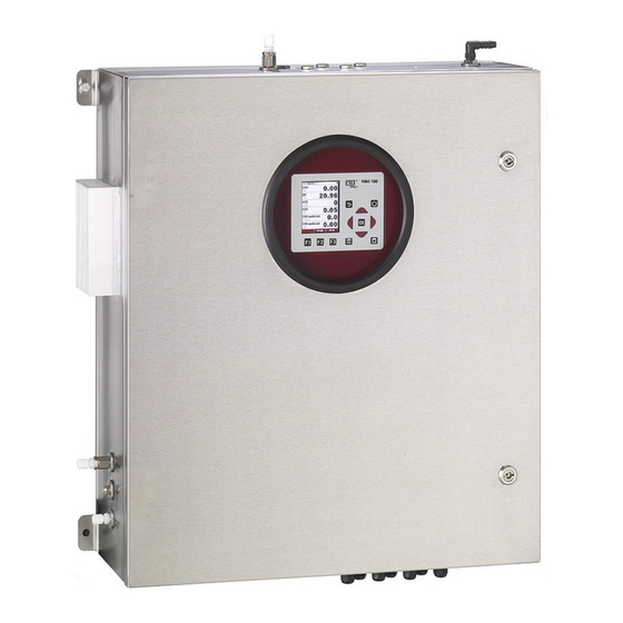
In case of system alarm, after analyser has auto-shut-off itself, the cabinet might contain an explosive atmosphere. Any ignition source must be avoided when opening the door. Keypad for operation of control unit. MRU GmbH, D-74172 Neckarsulm 17 / 108... - Page 18 Menu bar Function key bar Display panel - Menu - Measurement value, SD-Card in the slot - Indication green read- and write access - Indication yellow only read access (SD-Card write protected) 18 / 108 MRU GmbH, D-74172 Neckarsulm...
-
Page 19: Measurement Menu
Please read chapter 5 for Please read chapter 5 & 6 details. details. for details. No matter which menu is currently active you will return to the measurement menu by pressing the ESC key several times. MRU GmbH, D-74172 Neckarsulm 19 / 108... -
Page 20: Explosion Protection Systems Of Swg100Bio-Ex
No change to the wiring or change of components are allowed without prior information about the impact on the type of protection of these changes. Always ask feedback of MRU for the intended changes. 15.2. -
Page 21: Ch Measurement Of Inside Cabinet
CH4-NDIR bench used for biogas measurement. In case an explosive atmosphere is detected inside the cabinet, the SWG100BIO-EX outputs an alarm signal to the remote power supply box, which interrupts the power supply of the full instrument. MRU GmbH, D-74172 Neckarsulm 21 / 108... - Page 23 1 hour to max 2 hours. The alarm menu can be closed with the key F1 or ESC. The alarm is still active, the user will see a flashing red 'OFF' on the menu indication bar. MRU GmbH, D-74172 Neckarsulm 23 / 108...
-
Page 24: Remote Power Supply Box
When the SWG100BIO-EX outputs an alarm (due to internal CH4 detected or due to failed self test) it is required to switch off the instrument completely by means of an external power supply box, which shall be located in safe area, in the power supply distribution cabinet. 24 / 108 MRU GmbH, D-74172 Neckarsulm... - Page 25 The circuit diagram of above pictured device must be implemented by user as part of the safety concept. User can either use the remote power supply box as offered by MRU, or install inside the power distribution cabinet a similar circuit (see diagram in chapter 20.3) using a power contactor and push-start button.
-
Page 27: Sample Gas Measurement
A zeroing is recommended after every measurement point change. The screenshots below show the “One zeroing / cycle” and “One zeroing / sample point” in comparison. The two auto-configurations, which can be selected. MRU GmbH, D-74172 Neckarsulm 27 / 108... - Page 28 ” the zeroing time can be configured. EROING ZEROING Measuring site valves Valves closed Zeroing valve Valve open Duration 2min to 1 h Recommendation 5min., in general not to be changed by user as depending only on analyzer internal setup MRU GmbH, D-74172 Neckarsulm...
- Page 29 Purging (cycle phase details): The purging is a separate configuration point to purge the analyser with ambient • air through the zero gas inlet. It can be helpful, if the analyser must switch between a sample point with different sample gas concentrations. MRU GmbH, D-74172 Neckarsulm 29 / 108...
- Page 30 The activation and deactivation of a phase can be done in the cycle phase details of the concerning phase. Example for the deactivation of a phase In this example the “Measurement SP2” will be deactivated. The deactivated phase is grey out. MRU GmbH, D-74172 Neckarsulm...
- Page 31 SP2. Adjust the duration-phase at 15 min. and the suction/response time until the pure meas. time has arrow keys. the value of 3 min. Use for this operation the F1/F3 MRU GmbH, D-74172 Neckarsulm 31 / 108...
-
Page 32: H2Slow Sensor Protection (Optional)
The instrument is equipped with a cut-off solenoid valve and air purge pump to protect • the H sensor, without impacting the results of all other sensors. The purge unit is always activated after 3-10 minutes of active sensor measuring time. • 32 / 108 MRU GmbH, D-74172 Neckarsulm... - Page 33 • points. Instead the user may configure that the H sensor is active only added at some of the measurement cycles. MRU GmbH, D-74172 Neckarsulm 33 / 108...
-
Page 34: Analyzer Mounting And Installation
The measurement place must have enough space for installation and • maintenance works. The place should be protected for direct sunlight, rain and squalls. • The area around the analyzer must have enough space. • 34 / 108 MRU GmbH, D-74172 Neckarsulm... -
Page 35: Steps For The Mechanical Mounting And Installation
Mounting the analyser on a wall or a steel rack Installation of the power supply Installation of the external switch-off circuit Installation of the sample gas tubing Installation of the Modbus RTU (optional) Installation of the I/O modules MRU GmbH, D-74172 Neckarsulm 35 / 108... -
Page 36: Mounting The Analyser On A Wall Or Steel Rack
Be sure, that the air circulation is not obstructed. • Let enough room for the tubing or piping. • For outdoor installation Ensure that the analyzer is mounted on a rain and sun protected place (weather shade). 36 / 108 MRU GmbH, D-74172 Neckarsulm... -
Page 37: Correct Tubing Of The Swg100Bio-Ex
All connectors of the analyzer use female threads.The analyzer may be connected by tubing or piping. Distance, which should be fulfilled Min. 50 cm Min. 40 cm Do not cover the breather drain. Min. 30 cm MRU GmbH, D-74172 Neckarsulm 37 / 108... -
Page 38: Flow Restrictor Orifice (#65114)
Use PTFE strips to tighten the fitting inside the thread! G1/8“ out ISO parallel thread G1/8“ ISO parallel thread The flow restrictor orifices are installed on the sample gas inlets and on the calibration gas inlet. 38 / 108 MRU GmbH, D-74172 Neckarsulm... - Page 39 Fitting: 1/8 in. ISO parallel thread. Condensate outlet (Option: 65408) Fitting: 1/8 in. ISO parallel thread. Reference: 1. Fitting for PTFE tubing 4/6 mm G1/8” thread 2. Flow restrictor orifice G1/8” thread. 3. Zero gas filter G1/8” thread MRU GmbH, D-74172 Neckarsulm 39 / 108...
-
Page 40: Installation Of The Power Supply
For cables with Ø 3,5-10 mm. Pre-fuse Remote power supply circuit 100-230 Vac/ 47-60 Hz/ 300W to guarantee power down the analyser in Fuse 4A slow (by user) case of hazard. (See chapter 20.3) 40 / 108 MRU GmbH, D-74172 Neckarsulm... -
Page 41: Installation Of The External Switch-Off Circuit
The external electric contactor K1 is a part of the safety installation. It is required to be installed by user when power supplying the analyser. The circuit diagram below shows the correct wiring of the remote power supply box. MRU GmbH, D-74172 Neckarsulm 41 / 108... - Page 42 SWG100 BIOGAS User Manual 42 / 108 MRU GmbH, D-74172 Neckarsulm...
-
Page 43: Connection Of The I/O Module
Out1 and Out2 contacts are “fail safe” type: open contact in case of alarm or power failure closed contact for normal operation MRU GmbH, D-74172 Neckarsulm 43 / 108... - Page 44 0,2-2,5 mm² (30-12 AWG) Solid with ferrule (with/ or without plastic) 0,25-2,5 mm² Information for cables, which go through the cable gland M16: It is recommended to use only electric lines with ferrules. 44 / 108 MRU GmbH, D-74172 Neckarsulm...
-
Page 45: Power Up And Commissioning The Analyser
Date and time of the instrument Configure sample points Configure analog in and outputs of the I/O modules Configure the alarm relays Configure the Modbus RTU. CLOSE and LOCK the cabinet door of analyser END OF PROCESS MRU GmbH, D-74172 Neckarsulm 45 / 108... -
Page 46: Power Up The Analyser
The green LED on the remote power supply box will glow. Press for 3 sec. 4. The analyser will start and firmware will boot. Wait until the first Self-Test is completed. 46 / 108 MRU GmbH, D-74172 Neckarsulm... -
Page 47: Check Country And Language
Set suction delay and measuring time for each sample point according to your needs. Note: You may use the function 'auto-config', which will install typical settings. Then check the settings and modify them if needed. MRU GmbH, D-74172 Neckarsulm 47 / 108... -
Page 48: Configuration Of The Alarm Relays
ATTENTION Analyzer system alarm relay is a potential-free contact, which max. 24VDC/VAC and a current of 1A (max.) Connection of the alarm relay: Potential-free Max. 24VDC/VAC, 1 A (max.) MRU GmbH, D-74172 Neckarsulm... - Page 49 Information for cables, which go through the cable gland M16: It is recommended to use only electric lines with ferrules. Following analyzer errors will produce a system alarm (open contact of System Alarm relay) MRU GmbH, D-74172 Neckarsulm 49 / 108...
-
Page 50: Configuration Of The Modbus
It is recommended to use only electric lines with ferrules. Configuration at the analyzer 1. Open the path XTRAS ENERAL ETTINGS 2. Press “Modbus”. 3. The Modbus store settings will be open. The user can commission the slaves settings. MRU GmbH, D-74172 Neckarsulm... - Page 51 SWG100BIO Ex. User Manual MRU GmbH, D-74172 Neckarsulm 51 / 108...
-
Page 52: Configuration Of The External Control (Option: Io Module)
This feature can be used for externally controlled sampling point selection, zeroing and stand-by, using external potential free relay contacts, see also diagram in $4.4 The relay contacts build a 4-bit binary number: RC4 - RC3 - RC2 - RC1 open=0, closed=1. Let us tell this number 'status number'. MRU GmbH, D-74172 Neckarsulm... - Page 53 5 mA (4 mA+1 mA) the second is by 6 mA (4 mA + 2 mA) and so on until the 20 mA signal is reached. The connection of the one 4-20 mA signal is a two-wire connection. MRU GmbH, D-74172 Neckarsulm 53 / 108...
- Page 54 -Measurement: The measurement will be started after the response/ suction time is finished. It will be only abort, if the user changes the status of the external signal sources. The chart below shows the possible statues, which can be set at the analyzer: MRU GmbH, D-74172 Neckarsulm...
- Page 55 - status number=15 (for a few seconds, recommended min. 10 seconds) - status number=1 (for any time period, recommended max. 1 hour) After installation and power-up of the analyzer few steps should be processed in order to operate the instrument properly. MRU GmbH, D-74172 Neckarsulm 55 / 108...
-
Page 56: Configuration Of The Analog Outputs At The I/O Module
The equivalent concentration for 4 mA and for 20 mA. Assign measuring value and the min and max value to each analog output channel. Note: You may use the function 'auto-config', which will install typical settings. Then check the settings and modify them if needed. MRU GmbH, D-74172 Neckarsulm... -
Page 57: Configure Alarm Output Of I/O Module
Assign sampling point, measuring value, threshold value and the alarm direction (LO alarm, when below threshold or HIGH alarm when above threshold). ATTENTION You may use the fuction ‘auto-config’, which will install typical settings. Then check the settings and modify them if needed. MRU GmbH, D-74172 Neckarsulm 57 / 108... - Page 58 Calm Alarm ATTENTION With the test modus for the alarm outputs of the IO module, the alarm relays at the IO modules and the relay at the PCB mainboard can be activated. MRU GmbH, D-74172 Neckarsulm...
-
Page 59: Configure The Aux-Input On Software-Side
5. Important for the AUX-inputs is the measurement range. The range is set with the two points “Minimum 4 mA” and “Maximum 20 mA”. 6. Before the menu is left, a request to safe the configuration will appear. MRU GmbH, D-74172 Neckarsulm 59 / 108... -
Page 60: Operating The Analyser
If one of the internal RS485 bus participants are issuing alarm (faulty) status, the user can still leave the self-test manually by pressing F2='forward' (PIN code requested), even if not all sub- systems or the gas cooler are ready. NOTE: this is for service purpose only! 60 / 108 MRU GmbH, D-74172 Neckarsulm... -
Page 61: Main Menu Measurement
In the background, the analyzer uses the measurement cycle continues uninterrupted. However, once a measurement phase is completed, the display automatically switches to the actual measurement location. MRU GmbH, D-74172 Neckarsulm 61 / 108... - Page 62 As soon as you have finished the configuration, press the ESC key (or press again the menu key and select the function 'Save measuring window'). You will be asked, whether the changed settings shall be stored or discarded. Select 'keep them' in order to store your changes. 62 / 108 MRU GmbH, D-74172 Neckarsulm...
-
Page 63: Data Storage
When entering the menu the measurements of the last 24 hours will be displayed. This interval can be changed by pressing the keys F1=more or F3='less'. MRU GmbH, D-74172 Neckarsulm 63 / 108... -
Page 64: Power-Down Of Analyzer
You also may enter this menu by pressing the OFF key and leave it by pressing the ESC key (without starting the purge cycle) , when you just want to store operational data and user settings. 64 / 108 MRU GmbH, D-74172 Neckarsulm... -
Page 65: Backup/Restore All Individual User-Settings
Temperature cooler [°C ] more than Net calorific value [MJ/kg ] less than Gross calorific value [ MJ/kg ] less than Net calorific value [MJ/m3 ] less than Gross calorific value [ MJ/m3 ] less than MRU GmbH, D-74172 Neckarsulm 65 / 108... -
Page 67: Update The Firmware
3. If the SD-card is recognized, the analyzer will make a noise. 4. Open the path: . Dependent from the firmware update it can be XTRA EVICE necessary to open the different submenus. MRU GmbH, D-74172 Neckarsulm 67 / 108... - Page 68 4. The Update will start from the SD-card, if a firmware with the filename “1106mb.fwb” is at the SD-card. Update the NDIR-bench (Firmware-Update with filename “1106ndir.fwb”) Open the path: XTRA EVICE INFO F1/F3 F1/F3 68 / 108 MRU GmbH, D-74172 Neckarsulm...
- Page 69 I/O module. Be sure, that the device is “Mainboard” to update the I/O module. 4. The Update will start from the SD-card, if a firmware with the filename “1106iom.fwb” is at the SD-card. MRU GmbH, D-74172 Neckarsulm 69 / 108...
-
Page 70: Service And Maintenance
Check the switch-off relay and the cabinet Every month See chapter 9.2. ambient solenoid valve. Look if all flexible tubes are tight. Weekly Exchange the tubes to new one. Exchange flexible tubes, which are 70 / 108 MRU GmbH, D-74172 Neckarsulm... -
Page 71: Position And Overview Of The Service-Parts
In the follow chapters, there will be introduced some service parts, which are important for the reliable operation. These parts are independent from the regular checks and must be replaced in a regular interval of minimum 6 month. 21.3. Position and overview of the service-parts MRU GmbH, D-74172 Neckarsulm 71 / 108... - Page 72 The analyzer shows the warning “Gas flow is too low”. Sinterfilter New state: sintered surface Must be changed, if the PTFE filter is 2 pieces 65988 blocked. The analyzer shows the warning “Gas flow is too low”. 72 / 108 MRU GmbH, D-74172 Neckarsulm...
- Page 73 Remove the Install a new filter exhausted filter unit. unit. Remove the exhausted filter unit from the clip. Plug the viton tubes on the filter unit. Push the filter unit on the clip. MRU GmbH, D-74172 Neckarsulm 73 / 108...
- Page 74 Remove the Install a new filter exhausted filter unit. unit. Remove the exhausted filter unit from the clip. Plug the viton tubes on the filter unit. Push the filter unit on the clip. 74 / 108 MRU GmbH, D-74172 Neckarsulm...
- Page 75 (#65988) exchange both parts to a new one. The compensation parts can be found in the Copper seal service-set. (#61947) 3. The gas tube can now connect with the nozzle again. MRU GmbH, D-74172 Neckarsulm 75 / 108...
-
Page 77: Cleaning The Surface Of Swg100Bio-Ex
Check the following points: S. valve CH4 case from OFF to ON. The solenoid CH4 valve will make a noise. • Safety switch-off from ON to OFF. The analyser will power down. • MRU GmbH, D-74172 Neckarsulm 77 / 108... -
Page 79: Exchange Of Electrochemical Sensors
0-10.000ppm high10000ppm 65828 CO-Sensor 0-4000ppm 65827 H2-Sensor 0-1.000ppm It is important to consider, that only sensors can be replaced! The costumer has the opportunity to upgrade a new sensor type, it is necessary. MRU GmbH, D-74172 Neckarsulm 79 / 108... - Page 81 Remove the sensor from the main pcb (see sketch above). • Unscrew the sensor, by hand from the sensor manifold. • New sensor Screw the new sensor hand tight in the sensor- manifold. Plug the sensor cable on the • main pcb. MRU GmbH, D-74172 Neckarsulm 81 / 108...
- Page 83 • Push the round circuit board on the pins of the sensor. Be sure, that the pins of the circuit board has same designation with the pins from the sensor (for example: A-A, C-C...) • Mount the three fixing nuts hand-tight on the sensor. New sensor Circuit board MRU GmbH, D-74172 Neckarsulm 83 / 108...
- Page 85 To exchange the sensors, following steps must be done: • Remove the cable form the sensor. • Remove the old sensor. • Mount the new sensor hand-tight to the sensor module. • Plug the cable to its previous position. MRU GmbH, D-74172 Neckarsulm 85 / 108...
-
Page 86: Analyzer Calibration
Once in a while it is necessary to recalibrate the analyzer. The exact interval time depends on the biogas condition (gas concentration, total measuring time) and shall be determined by the user. MRU recommends at least half yearly calibration. Calibration is carried out by connecting certified gas cylinder to the analyzer. As those cylinders, typically are under high pressure (150 to 200 bar) and they contain toxic and/or flammable gases, make sure that only qualified personal is involved in this calibration procedure. - Page 87 Before the gas bottle can be installed the gas nozzle must be mounted on the calibration gas inlet. The gas nozzle reduces the incoming gas flow in the analyzer. MRU GmbH, D-74172 Neckarsulm 87 / 108...
- Page 88 First select the gas component, than press OK. A blue screen will show up appeared. With the arrow keys the gas concentration can be set. 4. After the gas composition is set, the interval for the calibration can be set, too. 88 / 108 MRU GmbH, D-74172 Neckarsulm...
- Page 89 If the gas concentrations are not differing too much, the measured values will be shown “green” on the display. 7. The new gas factors will be stored, after successful calibration. MRU GmbH, D-74172 Neckarsulm 89 / 108...
-
Page 90: Troubleshooting
- The ambient temperature is too - be sure, that ambient hot. temperature within operating range. - The gas cooler unit is defect. -Contact customer support. 90 / 108 MRU GmbH, D-74172 Neckarsulm... -
Page 91: Technical Specification
Typical gas flow Schnittstellen Interfaces Deutsch Angabe English Benutzerschittstelle Angabe User Interface Anzeigetyp 3,5TFT Display type Anzahl gleichzeitig Number of simultaneously displayed angezeigter Messwerte values Tastatur mit Anzahl Tasten Keyboard with qty of keys MRU GmbH, D-74172 Neckarsulm 91 / 108... - Page 92 0 .. 21 % Measuring Range Auflösung 0,01 % Resolution Genauigkeit abs. ± 0,2 Vol% Abs. Accuracy Ansprechzeit T90 < 20s Response Time T90 Jahre erwartete Lebensdauer an Luft Years expected lifetime (@air) 92 / 108 MRU GmbH, D-74172 Neckarsulm...
- Page 93 < 40s Response Time T90 Jahre erwartete Lebensdauer an Luft (abhängig von gewähltem Years expected lifetime (@air) Sensor) (Depending on chosen sensor) Elektrochemischer Sensor Electrochemical Sensor Nominaler Messbereich 0-1000 ppm Nom. Measuring Range MRU GmbH, D-74172 Neckarsulm 93 / 108...
- Page 94 ± 0,3 Vol% / Genauigkeit abs. /vom Messwert Accuracy abs./reading Ansprechzeit T90 < 35 s Response Time T90 Berechnete Werte Calculated values Deutsch Angabe English Messbereich Measuring range (fuel type (brennstoffabhängig) 0 - CO dependant) 94 / 108 MRU GmbH, D-74172 Neckarsulm...
-
Page 95: Declaration Of Conformity
SWG100BIO Ex. User Manual Declaration of conformity MRU GmbH, D-74172 Neckarsulm 95 / 108... - Page 97 SWG100BIO Ex. User Manual MRU GmbH, D-74172 Neckarsulm 97 / 108...
-
Page 99: Appendix
- 9600 baud or 19200 baud (recommended) - odd, even or none parity - 1 or 2 stop bits • The maximal number of 32bit-values to be read with one single read command is (126 modbus registers) MRU GmbH, D-74172 Neckarsulm 99 / 108... -
Page 100: Special Informationen About The Profibus Slave Function
27.2. Special informationen about the Profibus Slave function • The Profibus Slave function requires a modbus/profibus-converter "Seneca HD67561", which is configured and installed in the analyser. • Usually MRU sets the Profibus ID to 84. 100 / 108 MRU GmbH, D-74172 Neckarsulm... -
Page 101: Defined Registers To Be Read By The Master
(or CH4 [ppm], if CH4 [%] isn't available) H2S [ppm] (optional) H2 [ppm] (optional) Net calorific value [MJ/kg] Gross calorific value [MJ/kg] modbus profibus data register content address address type Net calorific value [MJ/m³] Gross calorific value [MJ/m³] MRU GmbH, D-74172 Neckarsulm 101 / 108... - Page 102 CO2 [ppm] (optional, when CO2 [%] also available) not (yet) defined (reads zero) Status & measurement values of sample point 3-10 (optional) 130-369 152... add 30/44 to the addresses for each sample point 102 / 108 MRU GmbH, D-74172 Neckarsulm...
- Page 103 8 AUX-values read by IO-modules 8 & 9 AUX-value read by IO-module 10 - Input 1 AUX-value read by IO-module 10 - Input 2 AUX-value read by IO-module 10 - Input 3 AUX-value read by IO-module 10 - Input 4 MRU GmbH, D-74172 Neckarsulm 103 / 108...
-
Page 104: Analyser Status (Address 0 And Some Mirror Addresses)
0020h 0010 0000 Measuring sample point 2 0030h 0011 0000 Measuring sample point 3 0012h 0001 0010 Measuring sample point 1 + System-Alarm 0000h 0000 0000 Adjustment (user interaction at the analyser) 104 / 108 MRU GmbH, D-74172 Neckarsulm... -
Page 105: Analyser System Alarm (Address 2 And Some Mirror Addresses)
Hexadecimal Binary state description 0001h 0000 0001 Mainboard is offline, measurement is halted 0008h 0000 1000 Condensate Alarm, measurement is halted 0050h 0101 0000 Sample flow < 20 l/h and T-gascooler > 10°C MRU GmbH, D-74172 Neckarsulm 105 / 108... -
Page 106: Spare Parts List
CO Power supply - #65325 Axial fan - #65097 For ventilation of analyzer cabinet Solenoid valve - #65470 Used for sampling point switching. Heater - #65425 Used for freeze protection of analyzer cabinet 106 / 108 MRU GmbH, D-74172 Neckarsulm... - Page 107 Display and operation unit #65133 Control unit for the user. I/O-Module #65179 + #65430 Used for analog output data transfer and sample point switching. I/O Module - #65179 Used for analog output data transfer MRU GmbH, D-74172 Neckarsulm 107 / 108...
- Page 108 SWG100 BIOGAS User Manual Technical data change w/o notice Date of issue: 20161220 REV01 20161221 REV02 20170912 REV03 20180523 108 / 108 MRU GmbH, D-74172 Neckarsulm...
Need help?
Do you have a question about the SWG100 BIOEX and is the answer not in the manual?
Questions and answers