Table of Contents
Advertisement
Quick Links
Advertisement
Table of Contents

Subscribe to Our Youtube Channel
Related Manuals for mru SWG 100 SYNGAS


Summary of Contents for mru SWG 100 SYNGAS
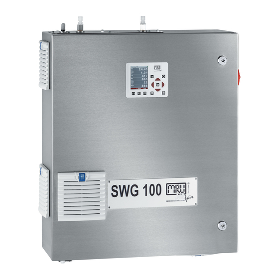
- Page 1 SWG 100 SYNGAS USER MANUAL...
- Page 2 Legal notices / Intellectual property rights comments Original user manual © 2021 by MRU No part of this manual my be published in any form (print, fotocopy, electronic media or any other publication form) without a written approval by the publisher.
-
Page 3: Table Of Contents
General important instructions for the plant operator ........... 7 1.5. Packing ......................... 8 1.6. Return of hazardous waste................... 8 1.7. Return of analyser ....................8 1.8. MRU Warranty conditions..................8 Analyser Description 0004 ..................9 2.1. Intended use ......................9 2.2. Principle of operation .................... 9 2.3. - Page 4 USER MANUAL SWG 6.3. Auto configuration ....................69 6.4. Insert a phase ..................... 70 6.5. Configuration of the phase details ..............70 6.6. Example for a measurement cycle configuration ..........73 Operating the analyser ..................76 0013 7.1. General process of the measurement cycle ............76 7.2.
-
Page 5: Information For Product And Safety
Information for product and safety 1.1. Safety manual All general information and safety precautions of MRU products are listed in the supplied separate safety manual. All information and safety precautions for the analyser in the Safety Manual also apply to the analyser. - Page 6 USER MANUAL SWG Toxicity danger of sample gas • WARNING Toxis gas Sample gas can be contain toxic substances, which are harmful for health and can even cause death. It is the responsibility of analyser user to ensure that person is skilled and trained in safety aspects of gases being analysed and procedures to follow while using this instrument.
-
Page 7: Weather And Environmental Conditions
These should be clarified with the manufacturer (MRU). Any additional protective measures for outdoor mounting have to be provided by the plant operator. The manufacturer (MRU) consults the plant operator in choosing appropriate protective measures. 1.4. -
Page 8: Packing
MRU must be returned prepaid. 1.6. Return of hazardous waste Waste Disposal/Returns/Warranty - MRU GmbH is required to accept the return of hazardous waste such as electro- chemical sensors that cannot be disposed of locally. Hazardous waste must be returned to MRU prepaid. 1.7. -
Page 9: Analyser Description 0004
Analyser Description 0004 • Read and observe the separately supplied Safety manual. • This manual enables you to understand and safely operate this MRU Analyzer. • Please read this manual with great vigilant. • Get familiar with the product before using it. - Page 10 USER MANUAL SWG are included, each operating with a different optical path length and stabilized by referring to a reference detector. The IR source is a highly efficient and stable IR emitter, pulsed at a frequency of several Hertz. By design NDIR technique offers good stability and selectivity together with long lifetime of sensor (only limited by corrosion or dust, which can be prevented or removed by regular servicing the instrument).
-
Page 11: Packing Dimensions And Designations 0005
USER MANUAL SWG 2.3. Packing dimensions and designations 0005 Packing dimensions: LxWxH [mm] = 700 x 800 x 180 Reference: Fan filter Calibration gas inlet Zero gas inlet Condensate outlet Cable gland for power supply Filter unit Cable gland for IO modul Sample gas inlet G1/8 inner thread Sample gas inlet for heated sampling line Sample gas outlet (VENT) G1/4... - Page 12 USER MANUAL SWG H3PO4-inlet G1/8 inner thread Page 12 of 129...
- Page 13 USER MANUAL SWG Connection options at inputs and outputs 0012 Connection system Position G1/8 inner thread 2 / 3 / 4 / 9 G1/4 inner thread Fitting list (scope of supply) Position Description Article number 1 / 2 / 3 / 4 / 9 Fitting G1/8 inner thread to DN 6/4 hose 55764 Fitting G1/4 inner thread to DN 6/8 hose...
-
Page 14: Sd-Card: Position And Content
USER MANUAL SWG 2.4. SD-Card: Position and content Following content are on the SD-Card: • Ethernet-Converter manual • Profibus-Converter manual • GSD-Files for profibus-converter • Analyser- manual (EN/DE) • Analyser ModBus/Profibus specification (EN/DE) The SD-card can be found in the SD-card slot in the device (see sketch below). Page 14 of 129... -
Page 15: Safety Concept Of Syngas Analyser 0016
USER MANUAL SWG Safety concept of syngas analyser 0016 • WARNING This device is not suitable for use in explosive areas. It does not have ATEX or comparable approvals. The Syngas instrument was designed to measure the quality of useful gases. Since these gases are often present in explosive concentrations, the instrument has some safety measures which are explained in this chapter. -
Page 16: Installation Manual 0006
USER MANUAL SWG Installation manual 0006 3.1. Overview This manual explains how to install the analyzer mechanically and electrically. Page 16 of 129... - Page 17 USER MANUAL SWG The installer must correctly assemble these parts during installation. The following diagram shows the sequence in which the installation should be carried out: Preparation of the measurement points (see 3.2) Analyzer mounting (see 3.3) Power supply (see 3.5) Connect IO module to control room (see 3.6) Connect sample gas inlet Connect zero gas outlet, adjustment gas inlet and condensate outlet.
-
Page 18: Select Measurement Point
USER MANUAL SWG 3.2. Select measurement point The measuring point should be in an area where the flow no longer has any particular turbulence. That is: • Not directly before or after a pipe elbow. The measuring point must be at least 3 times the chimney diameter from a bend. •... - Page 19 USER MANUAL SWG Picture 1: Dimensions for the wall mounting. Min. 500 mm Min. 300mm Min. 300 mm Min. 300 mm • CAUTION Only operate the analyzer in an upright position! Only power the device up after it is correctly mounted! General installation rules •...
-
Page 20: Installation Of Pressure Reducer Unit
USER MANUAL SWG 3.4. Installation of pressure reducer unit • DANGER Explosion hazard Do not operate the analyser without pressure reducer unit. • DANGER Explosion hazard The measuring point must not have an overpressure of 150 mbar. • WARNING As part of the safety concept, a reducing unit must be installed on each Autocal inlet. - Page 21 USER MANUAL SWG Male connector G1/8 Sinter filter Nozzle O-ring The pressure reducer unit must be installed at the sample gas inlets. It is a part of the safety concept of the analyzer, which must be observed. Correct installation of the pressure reducer unit: •...
-
Page 22: Connection Of Main Power Supply
The shut off box is necessary to power up and down the analyzer in a safe area. It prevent that a brake away spark is generated in the industrial area. The shut off box belongs to the safety concept of the analyser. The Remote Power Supply Box as optionally supplied by MRU, has a switch-off contactor (K1) , with 3 make contacts (normally open). - Page 23 USER MANUAL SWG WARNING Electrical shock! Electricity could cause damage, injuries and even death! Only educated staff should install the device. The analyser needs a main power supply of 100-230 VAC/ 47-60 Hz. The power supply will be connected on the hat-rail. Exactly: Reference: 1 T1-Relay...
- Page 24 USER MANUAL SWG Page 24 of 129...
-
Page 25: I/O Modules: Installation And Setting
USER MANUAL SWG 3.6. I/O modules: Installation and setting The IO module is for monitors and allows for remote operating of the analyser. An IO module has the following features: • Transmit 4-20 mA output. • Trigger alarm outputs. • Reads one PT1000. - Page 26 USER MANUAL SWG Analog output current 4-20 mA load resistor is max. 500 Ohm. Analog output does not require power supply. NOTE Open contact in case of alarm or power failure. Closed contact for normal operation. Plug connector definition: • WARNING Electric voltage Power the system down and protect for reconnecting before...
-
Page 27: Installation: Calibration Gas / Zero Gas And Condensate Outlet
USER MANUAL SWG 3.7. Installation: Calibration gas / zero gas and condensate outlet • WARNING As part of the safety concept, a reducing unit must be installed on each Autocal input. • WARNING As part of the safety concept, a reducing unit must be installed on each sample gas input. - Page 28 USER MANUAL SWG Reference: 2. Zero gas inlet with G1/8 inner threads and connector for DN4/6 mm hoses 3. Calibration gas inlet with G1/8 inner threads and connector for DN4/6 mm hoses Page 28 of 129...
- Page 29 USER MANUAL SWG Detail B: Reference: 4. Condensate outlet with G1/8 inner thread and connector for DN4/6 mm hoses 5. Sample gas outlet with G1/4 inner thread and connector for DN12/6 mm hoses. Installation calibration gas inlet (see detail A-3) •...
- Page 30 USER MANUAL SWG Installation condensate outlet (see detail B-4) • WARNING Condensate can be acidic or basic. Can cause chemical burns. The condensate output is located on the left bottom side of the analyser. It is equipped with a DN4/6 mm screw connection. The condensate from the gas coolers is discharged from the condensate outlet.
- Page 31 USER MANUAL SWG Installation sample gas outlet (VENT) (see detail B-5) • WARNING The gas outlet must not be closed. • WARNING The tubing should be positioned so that the gas can escape from the analyser almost without pressure. • WARNING The line should therefore not be longer than 10 m and should be laid with almost no kinks.
- Page 32 USER MANUAL SWG...
-
Page 33: Binding To A Process Control System: I/O Modules 0008
USER MANUAL SWG Binding to a process control system: I/O modules 0008 The IO module is a necessary module for the signal forwarding, into a control room. This module is an interface for signal transmitting, remote operating and to read signals, from extern transducers. -
Page 34: Pin Assignment
USER MANUAL SWG 4.2. Pin assignment The follow pin assignment-plan shows where the different pins for the interfaces can be found and which pins has a double occupancy. Page 34 of 129... - Page 35 USER MANUAL SWG max. max. Load Internal Double Description Abbrevation external (for load (in occupancy Voltage outputs) inputs) max. AO1+ 500R max. AO1- 500R max. AO2+ 500R max. AO2- 500R max. AO3+ 500R max. AO3- 500R max. AO4+ 500R max. AO4- 500R AL1+...
-
Page 36: Analog Outputs 4-20 Ma
USER MANUAL SWG 4.3. Analog outputs 4-20 mA Hardware-side green labels. Reference: Analog output 1 minus Analog output 1 plus Analog output 2 minus Analog output 2 plus Analog output 3 minus Analog output 3 plus Analog output 4 minus Analog output 4 plus Information for connection: Conductor cross section:... - Page 37 USER MANUAL SWG Software-settings • Open the menu: (1). XTRAS NALOG OUTPUT CONFIGURATION • The overview screen appears. This menu shows, how much analog-outputs are available and how the analog outputs are occupied. • At the overview screen all analog-outputs are listed. The amount of the analog-outputs is dependent from the amount of the installed IO-modules.
- Page 38 USER MANUAL SWG • List of the installed analog output ports (1): At this list the operator can select, which analog-output should be configured. To select an analog- output, move the up/down arrow keys. • Details (2): Here the operator can open the configuration screen for the selected output port.
- Page 39 USER MANUAL SWG Meas. Item (3): At this point the operator selects the measurement item, which should be transmitted. At the chart below, the typical measurements items are listed. Basically, all measurement-channels, which can be measured, can be selected at this point. Meas.
- Page 40 USER MANUAL SWG 1. Example: 4-20 mA signal outputs to control room Starting position: A plan wants to read the measurement values from the CO2 channel to their . The SWG100 has only one IO module and three sample points. All outputs are free.
- Page 41 USER MANUAL SWG Set points here with arrow keys and OK • In the last step the menu must be closed. Confirm the store message. The 4-20 mA output is now configuring. Page 41 of 129...
-
Page 42: Alarm Outputs
USER MANUAL SWG 4.4. Alarm outputs Hardware side: Every IO module has two alarm outputs. The position of the alarm-outputs are marked with the red labels. Reference: 1 Alarm Relay + 1 Alarm Relay - 2 Alarm Relay + 2 Alarm Relay - Information for connection: Conductor cross section: Relays-type:... - Page 43 USER MANUAL SWG Software-side • Open the menu: (1). XTRAS NALOG OUTPUT CONFIGURATION • The overview screen appears. This menu shows, how much alarm-outputs are available and how the alarm outputs are occupied. At the overview screen all alarm-outputs are listed. The amount of the alarm-outputs is dependent from the amount of the installed IO- modules.
- Page 44 USER MANUAL SWG • Details (2): Here the operator can open the configuration screen for the selected alarm output. To open the details-menu, push • Auto configuration (3): If the operator pushes this key ( ) the output pins would be configured by default values. •...
- Page 45 USER MANUAL SWG Meas. Unit (4): This point shows, which unit the transmit signal have. This point cannot be changed. Threshold (5): Here the threshold will be determined. Alarm of value is (6): The operator can determine, if the alarm will be triggered above the determine threshold, or below the threshold.
- Page 46 USER MANUAL SWG • The follow screen appears. To configurate the channel 1, the red marked positions must be changed: Page 46 of 129...
-
Page 47: Analog Inputs (4-20 Ma)
USER MANUAL SWG 4.5. Analog inputs (4-20 mA) Hardware-side: The analog inputs are on the top of the IO module. They are marked with a blue label. Through the help of the analog inputs, the IO module can read all common 4-20 mA transducer in the analyzer directly. - Page 48 USER MANUAL SWG 2-wire transducer: Transducer Load: 50 Ohm Power supply for transducer 4-wire transducer Transducer Load: 50 Ohm Power supply for transducer Page 48 of 129...
- Page 49 USER MANUAL SWG Software-side • Open the menu: (1). XTRAS UX INPUT CONFIGURATION • The overview screen appears. At the overview-screen, the installed AUX- inputs are listed. Every IO module has four AUX-inputs. At the default settings all AUX-inputs are deactivated (OFF at the overview-screen). •...
- Page 50 USER MANUAL SWG At this point the operator selects the measurement item, which should be transmitted. At the chart below, the typical measurements items are counted. Basically, all measurement-channels, which can be measured, can be selected at this point. This point shows, which unit the transmit signal have. This point cannot be changed.
- Page 51 USER MANUAL SWG • First the operator sees an overview, which shows with kinds of sensors are mounted at the IO-module. In this example, there is no transducer mounted at the SWG100. • To configure a new sensor, push • The follow screen appears.
-
Page 52: Configuration Of The External Control (Option: Io Module)
USER MANUAL SWG 4.6. Configuration of the external control (Option: IO module) This feature requires an I/O module (optional) and the function must be activated This feature can be used for the external control of the analyser. With the help of the external control follow operations can be done: •... - Page 53 USER MANUAL SWG Connection of the external control via relay contact This feature can be used for externally controlled sampling point selection, zeroing and stand-by, using external potential free relay contacts, see also diagram in $4.4 The relay contacts build a 4-bit binary number: RC4 - RC3 - RC2 - RC1 open=0, closed=1.
- Page 54 USER MANUAL SWG Connection of the external control via 4-20 mA input signals The signal inputs built a 4-bit binary number: I4 I3 I2 I1: 0-11 mA=open=0; 11/12-20 mA=closed=1. Status of external signal Status number Description source Automatic sampling point switching Analyzer is sampling the point SP1 (*1, *2) Analyzer is sampling the point SP2 (*1, *2) Analyzer is sampling the point SP3 (*1, *2)
- Page 55 USER MANUAL SWG Connection of the external control via one 4-20 mA input signal The user has the opportunity to control the analyzer with only the first 4-20mA input (see sketch below). The different commands will be given by the changing of the current signal.
- Page 56 USER MANUAL SWG Connection of the external control via Modbus A further option is, to control the external control via Modbus. To do this, follow steps must be done: • Connect the RS485 to Modbus converter to the Modbus connector found at the main pcb.
- Page 57 USER MANUAL SWG • If a valid input state (>0) is present, an arrow in the title line will appear. The analyzer is now slave and will perform the measurement until it gets another command from the master unit. Some external control settings can be configured. This can be found at the path: then = ext.crtl.
- Page 58 USER MANUAL SWG analyzer will purge the sensors, then it will close all solenoid valves and switch off the gas pump. When the status number changes back to a value less or equal afterwards the selected sample point will be measured. Example : - status number=1 (for any time period, recommended max.
-
Page 59: Analyser Commissioning Manual0009
USER MANUAL SWG Analyser commissioning manual0009 5.1. Power up the analyser • Open the case door of the analyser. • Power up the circuit breaker. See figure below. Detail A: Reference: 1. Circuit breaker for analyser 2. Circuit breaker for heated sampling hose (optional) 3. -
Page 60: Checking List For Commissioning
USER MANUAL SWG • Press the power switch of the remote power supply box. Wait until the system is ready for operation. The green LED on the remote power supply box will glow. Press for 3 sec. • The analyser will start and firmware will boot. Wait until the first Self-Test is completed. -
Page 61: Check Date And Time Of The Instrument
USER MANUAL SWG The analyser will automatically set some country-typical parameters like the language, the date format, the temperature unit, the daylight saving time function and the CSV-export settings. 5.4. Check date and time of the instrument The analyser stores automatically measurement values including timestamps. Therefore the instruments' system clock should be set correctly. -
Page 62: Configuration Of The Alarm Relays
USER MANUAL SWG 5.5. Configuration of the alarm relays contact. The following errors will turn the relay from NC to NO. Internal RS485 bus communication failure Analyser is in bootloader phase Gas leakage inside analyser cabinet (CH4 > 20% to 50% LEL) Condensate alarm (contacts resistance <... - Page 63 USER MANUAL SWG Detail A: Alarm-Relais Page 63 of 129...
- Page 64 USER MANUAL SWG Plug connector definition for the system alarm relay Slit screws Stripping length: 7 mm Tightening torque min.-max.: 0,5-0,6 Nm Conductor cross sections, which can be used: Type of electric line Conductor cross section min.-max. Solid 0,2-2,5 mm² (30-12 AWG) Stranded 0,2-2,5 mm²...
-
Page 65: Configuration Of The Modbus
USER MANUAL SWG 5.6. Configuration of the Modbus The Mobdbus connector can be found on the PCB-distributor (see sketch below). Reference for user RS-485 (Modbus RTU): 1. GND 2. B_EXT- 3. A_EXT+ Plug connector definition for the system alarm relay Slit screws Stripping length: 7 mm... - Page 66 USER MANUAL SWG Configuration at the analyser 1. Open the path XTRAS ENERAL ETTINGS 2. Press 3. The Modbus store settings will be open. The user can commission the slaves settings. Page 66 of 129...
- Page 67 USER MANUAL SWG Software side: Adjustment for the option auto-calibration: • ”. Adjustment MENU ETUP AUTO CALIBRATION • composition from the calibration gas cylinder. With the can be set. Arrow keys left/ right: With these keys the gas composition can be set. Arrow keys up/ down: Single positions for the different gas...
- Page 68 USER MANUAL SWG • The user has the following options: • - leave the menu: The set gas concentrations are stored and the auto calibration will start after the interval is reached. • - Start the auto- calibration immediately: Press (start now).
-
Page 69: Cycle Configuration 0010
USER MANUAL SWG 6. Cycle configuration 0010 6.1. Path and default setting Extra/ Measurement cycle config. “M .” When the menu is selected the user definable setting for the EASUREMENT CYCLE CONFIG measurement cycle will appear (see screenshot below). Screenshot shows default setting, when the „M .”... -
Page 70: Insert A Phase
USER MANUAL SWG The two auto-configurations, which can be selected. Depending on the analyser type, the first or the first and second phase cannot be deleted, deactivated or moved to another position. Delete a phase With a phase can be deleted. To do this, select the phase, which should be deleted and press Screenshot shows how a phase can be deleted. - Page 71 USER MANUAL SWG Measurement SPX (Cycle phase details): measurement time and the suction delay can be configured. Each sample point can be configured individually. In the cycle phase details the following times can be set: MEASUREMENT SPx Measuring site valves Valve of selected site is open, others closed Zeroing valve Valve closed...
- Page 72 USER MANUAL SWG PURGING Measuring site valves Valves closed Zeroing valve Valve open Duration 30 sec. to 1 h Activated/deactivated a phase The user has the opportunity to deactivate a phase in the measurement configuration cycle. This could be necessary for example if a sample point is temporarily not in use. The activation and deactivation of a phase can be done in the cycle phase details of the concerning phase.
-
Page 73: Example For A Measurement Cycle Configuration
USER MANUAL SWG 6.6. Example for a measurement cycle configuration In this chapter an individual measurement cycle should be created with the features described at the chapters below. The measurement cycle should have the following sequence: Following points must be done to configure the individual measurement cycle: •... - Page 74 USER MANUAL SWG F1/F • Leave the cycle phase detail and select the next phase. Select with the left/right arrow keys the cycle phase detail. Adjust the phase-duration at 15 min. and leave the cycle phase detail. • Switch to the next point and select with the left/right arrow the measurement SP1.
- Page 75 USER MANUAL SWG Leave the menu and safe the adjustments. The individual configuration is done. Page 75 of 129...
-
Page 76: Operating The Analyser 0013
USER MANUAL SWG 7. Operating the analyser 0013 This chapter has the follow structure: • In the first part it will be explained, how to start the analyser and the selftest menu. • Part three shows the submenu, which are listed at the EXTRA menu. •... - Page 77 USER MANUAL SWG NOTE: this is for service purpose only! Main menu measurement This menu is the root of all menus and will be shown automatically as soon as the self-test is finished. The title bar you can see on the left the current measurement cycle status and how long it lasts and the actual sampling point number.
- Page 78 USER MANUAL SWG and down. The arrow keys left and right will change the measuring value in the selected line. When the cursor is moved over the top or under the bottom line, then the next definable page will show up. As soon as you have finished the configuration, press the ESC key (or press again the menu key and select the function 'Save measuring window').
-
Page 79: Data Storage Menu
USER MANUAL SWG 7.2. Data Storage Menu The data storage menu can be reached by pressing 'storage' in the measurement menu: The menu provides an overview of stored measurements of each sample point and of the memory usage. NOTE DATA STORAGE The analyser makes use of an internal flash memory to store measurement values automatically. - Page 80 USER MANUAL SWG General information about the data storage Data storage strategy is as follows: • The analyser may store up to 20,000 measurement points (including all relevant data). • At the end of each measurement cycle (per sampling point) the current values will be stored.
- Page 81 USER MANUAL SWG Export of measurements to SD card This function is used to export the measurements from the analyser to a PC. The used format is CSV (comma-separated values). Many computer programs are able to read this format, e.g. spread sheet calculation programs. The CSV format is not exactly the same in all countries.
- Page 82 USER MANUAL SWG • Set maximal list: In this list all available measurement values and all 9 asset lines are pictured. • Set default list: In this list all available measurement values and 2 asset lines are pictured. • Set small list: In this list the general measurement values are pictured.
- Page 83 USER MANUAL SWG Power-Down of analyser Before the analyser is disconnected from mains, it should be prepared for the Power-Down, because • operational data should be stored • eventually changed user settings should be stored • the sensors should be purged with fresh air Press the key in any menu in order to prepare the analyser for the Power- Down.
-
Page 84: Update The Firmware
USER MANUAL SWG 7.3. Update the firmware The analyser and different installed options can be updated, if it is necessary. Following options can be updated: • The firmware from the analyser. • The firmware from the pcb- mainboard. • The firmware from the NDIR-bench. •... - Page 85 USER MANUAL SWG Reference: 1. Name of the updateable device. In this example the multi gas bench (MGB). 2. FW update. The chart below shows the different updateable systems. Number Device MGB ( multi gas bench) IO module MCM (Measurement control modul) Valve control module Condensate pump module Gas cooler module...
- Page 86 USER MANUAL SWG Update the analyzer (Firmware- 1. Open the path: XTRA EVICE F2 = details 2. Press to open the details for the main device menu. 3. Press F2 = FW update . The analyser will start the update from the SD-card. Update the pcb-mainboard (Firmware- •...
- Page 87 USER MANUAL SWG • The Update will start from the SD-card, if a firmware with the -card. Update the IO modules (Firmware-Update with filena Open the path: XTRA EVICE INFO • Press F3 = sub.syst UB SYSTEMS INFO • Press F2 = details , to open the details from the I/O module.
-
Page 88: Service And Maintenance
USER MANUAL SWG Service and maintenance 0018 For a reliable function and high measurement quality it is necessary to inspect and service the analyser regularly. Besides the regular routine control by the operator (see chapter 8.1) the producer recommends a regular half year maintenance, which must carried by a qualified specialist. -
Page 89: Description Of The Analyser
USER MANUAL SWG 8.3. Description of the analyser Page 89 of 129... - Page 90 USER MANUAL SWG The sketch below shows the positions of all spare and consumable parts in the SWG-100. The parts, marketed with a red circle is a spare part, the parts, marketed with a green circle is a consumable part. Page 90 of 129...
- Page 91 USER MANUAL SWG Content of the service-set Single components can be offered under their article number directly. Reference / Legend: Red label Green label Spare parts Consumable parts Page 91 of 129...
- Page 92 USER MANUAL SWG Picture shows service flap from the analyser unit. Recommended Articel exchange number intervall Spare parts 6month PTFE filter element 12685 6 month Acid gas filter 56795 6 month Disc filter PTFE 64459 6 month Active coal filter 65034 Consumable parts If necessary...
- Page 93 USER MANUAL SWG Position 1: Acid-gas filter (#56795) Required materials 2x Acid gas filter (#56795), contained in the service- set. Required tools: Needle-nose pliers. Exchange interval: Exchange necessary, if filter turns from purple to white. Steps: 1. Remove exhausted acid gas filter from the clips.
- Page 94 USER MANUAL SWG Position 2 and 3: Dust- and particle filter (#65533 and #66088) Required materials : Dust- and particle filter (#65533 and #66088) contained in the service set. Required tools: needle-nose pliers. Exchange interval: Exchange necessary, if the filter gets dark or black. Steps: Pull the viton-tubes from the filter unit with the hand.
- Page 95 USER MANUAL SWG Steps: Open the filter-unit by pulling the blue lash. Replace the exhausted filter mat through a new one. Close the cover from the filter unit. Page 95 of 129...
- Page 96 USER MANUAL SWG Spare part 3: PTFE filter Reference: 1. Filter element 2. Filter glass 3. Holding ring 4. Filter holder Unscrew the holding ring (3). Remove the filter glass (2). Unscrew the filter holder (4). Exchange the exhausted filter element with a new one (1). Spare part 5: Disc filter PTFE Power the system down.
-
Page 97: Exchange The Condensate Pump Head Unit
USER MANUAL SWG 8.4. Exchange the condensate pump head unit • Unscrew and remove the cover from the condensate pump. • inner assembly condensate pump head is shown in the picture below. • inner assembly condensate pump head is shown in the picture below. - Page 98 USER MANUAL SWG • Remove the pump roller assemble. Assemble the condensate pump head units • Insert the upper condensate pump hose. • Insert the pump roller assemble. Press the part into the groove. • Insert the lower condensate pump hose. •...
- Page 99 USER MANUAL SWG Page 99 of 129...
-
Page 100: Specification Modbus Via Rs485 Specification 0016
USER MANUAL SWG Specification Modbus via RS485 specification 0016 9.1. General information The Modbus (slave function) requires the firmware version V1.01.70 dated 17.11.2014 or later. The analysers are able to work as modbus slave using the RS232 or RS485 port (possibly with external RS232/RS485 adapter) supports RS485 interface with 2/4 wires (half/full duplex) supports only the binary Modbus protocol (RTU) - Page 101 USER MANUAL SWG Defined registers to be read by the master protoc data numb. of register content type registers address Status & Device info (more details read below) Analyser Status (more details read below) System Alarm Serial number (11060 = SWG100biogas) Analyser type (e.g.
- Page 102 USER MANUAL SWG protocol data numb. of register content address type registers Status & measurement values of sample point 1 (more details read below) Analyser Status (more details read below) System Alarm O2 [%] CO2 [%] CH4 [ppm] H2S [ppm] H2 [ppm] CO [ppm] NO [ppm]...
- Page 103 USER MANUAL SWG protocol data numb. of register content address type registers AUX-values (read by up to 10 IO-modules) AUX-value read by IO-module 1 - Input 1 AUX-value read by IO-module 1 - Input 2 AUX-value read by IO-module 1 - Input 3 AUX-value read by IO-module 1 - Input 4 AUX-value read by IO-module 2 - Input 1 AUX-value read by IO-module 2 - Input 2...
-
Page 104: Analyser Status (Address 0 And Some Mirror Addresses)
USER MANUAL SWG 9.2. Analyser Status (address 0 and some mirror addresses) The Analyser Status is a 32bit-word and must be interpreted bitwise. Description (until the first zeroing has been done) Power-On System-Alarm, see table below Air Purging (zeroing) Gas Sampling (preparing measurement, not measurement!) (1..10, reads 0 while air purging) Currently sampled sample point number 8-31... -
Page 105: Adjustment: Ndir-Bench (Mgb-Module)
USER MANUAL SWG Adjustment: NDIR-bench (MGB-Module) ATTENTION Close door During the entire adjustment, the cabinet door must be closed. ATTENTION The PIN-Code is: F1 F3 F2 F2 UP - DOWN • Select the menu: and input the 6 symbols XTRAS DJUSTMENT MENU password. - Page 106 USER MANUAL SWG • Mounting the adjustment gas cylinder: The pressure reducer must be set at max. 500 mbar. The adjustment gas cylinder remains closed. • Open NDIR cuvette menu: Open the menu XTRAS DJUSTMENT MENU . Here the values should now be close to zero. The menu ADJUSTMENT has the follow structure: Reference:...
- Page 107 USER MANUAL SWG • Open adjustment gas cylinder: Open the adjustment gas cylinder. The actual value changes. After 1 until 2 minutes the values should no longer change. If the value is adjustable, the set value is shown in quotation marks. open P=500 mbar •...
-
Page 108: Technical Specification
USER MANUAL SWG Technical specification Allgemein General Deutsch Angabe English Betriebstemperatur(ohne +5°C ... +45 °C / 41 °F ... 113 Frostschutzheizung) °F Operating temperature (w/o heating) Betriebstemperatur (mit -10 °C ... +45°C / 14 °F ... 113 Operating temperature (with internal optionaler Frostschutzheizung) °F heating, option) - Page 109 USER MANUAL SWG Schnittstellen Interfaces Deutsch Angabe English Benutzerschnittstelle Angabe User Interface Anzeigetyp 3,5TFT Display type Anzahl gleichzeitig angezeigter Number of simultaneously displayed Messwerte values Tastatur mit Anzahl Tasten Keyboard with qty of keys Elektrische Aus-/Eingänge Electrical I/O Serielle Schnittstelle RS485 Serial interface Protokoll...
-
Page 110: Appendix
USER MANUAL SWG Appendix Page 110 of 129... -
Page 111: Installation: Hd Probe With Heated Sampling Line
USER MANUAL SWG 12.1. Installation: HD probe with heated sampling line HD-probe with back-purge: • Probe internally heated • Probe tube is exchangeable • Filtering with sinter filter cartridge • For lines with and without heating hose • With back-purge function •... - Page 112 USER MANUAL SWG Installation of the sample probe (3) • Connect the PTFE-tube with the HD-sample probe. For the connection use the bulkhead connector. Reference: Front ferrule Back ferrule Tube insert PTFE-hose • Install the cable set for the probe. •...
- Page 113 USER MANUAL SWG Reference: 1. PTFE-hose from heated sampling line 2. Harness from heated sampling line. Reference: Heated sampling line (number 1-10) 1. L Hose brown 2. N Hose blue 3. Th+ Hose green 4. Th- Hose white 5. L probe violet 6.
- Page 114 USER MANUAL SWG Page 114 of 129...
-
Page 115: Maintenance: Hd-Probe With Back Purge Function
USER MANUAL SWG 12.2. Maintenance: HD-probe with back purge function Over time, flat and O-ring seals must be replaced. The following service set can be ordered for maintenance. Recommended exchange Name Articel intervall number If necessary 1 Ceramic filter 0,5µm D50 55764 If necessary 2 Sealing DURANOARD for ceramic filter... - Page 116 USER MANUAL SWG Positions of the components Page 116 of 129...
- Page 117 USER MANUAL SWG Preparations • Power the system down. • Remove the probe cover. • Unscrew the filter holder. Pull the locking device downwards. • Pull out the filter holder. Page 117 of 129...
-
Page 118: Maintenance: Filter Holder
USER MANUAL SWG 12.3. Maintenance: Filter holder Follow maintenance steps must be done, at the filter holder. • Unscrew the filter holder nut. Open Size Position-No.: 17 mm • Remove the exhausted ceramic filter and the two sealings. • Remove the exhausted O-rings and replace with new ones. •... - Page 119 USER MANUAL SWG Close Size Position-No.: 17 mm • To exchange the O-rings at the backpurge manifold, unscrew the upper nut and remove the manifold. • Inside the manifold are two O-rings, which must be replaced. Page 119 of 129...
- Page 120 USER MANUAL SWG Exchange the seals • Power the system down. • Remove the HD-probe from the flange adapter. To do this, remove the nuts. Open Size Position-No.: 17 mm • Remove the entire HD-probe from the stack carefully. • The graphite seal can now remove and replace with a new one.
- Page 121 USER MANUAL SWG • Unscrew the probe tube from the HD probe. And replace the old seal with a new one. NOTE • When assembling, lubricate the screws with ceramic paste to prevent them from seizing. Page 121 of 129...
-
Page 122: General Instructions For The Heated Sampling Lines
USER MANUAL SWG 13.1. General Instructions for the heated sampling lines For the save operation of the sample line it is important that it is installed correctly. This includes the following points: • The bending radius as given below is maintained, •... - Page 123 USER MANUAL SWG Bending radius of heated sampling lines The picture below shows the minimal bending radius. Bending radius min. = 32 cm ATTENTION Falling below the bending radius will reduce life time of the sampling probe. Page 123 of 129...
- Page 124 USER MANUAL SWG Mounting rules for heated sampling lines Basic rules for laying the heated sampling lines Wrong Right Do not lay several heated sampling lines Care for enough space between the close together. -> Overheating hazard!! single heated sampling lines. Do not use clips, being too tight.
- Page 125 USER MANUAL SWG application. Please, consider this during layout. Do not assemble the heated sampling line To avoid that the heated sampling line when it is twisted!! gets twisted, assemble it parallel. Do not assemble the heated sampling line Use a special spring suspension. that the whole application can sag from its one weight.
- Page 126 USER MANUAL SWG Rules for laying the heated sampling line in a cable duct Wrong Right Do not lay heated sampling lines in a Use cable ducts, where the air can get closed cable duct. -> Overheating hazard!! out. Page 126 of 129...
- Page 127 USER MANUAL SWG Page 127 of 129...
- Page 128 USER MANUAL SWG 20.12.2021 14:11:21 f=0.31 O:\Produkte\SWGx00_1131\Referenz-Gaslaufpläne\GLP_SWGx00Syngas_1131_211202.sch (Sheet: 1/1) Page 128 of 129...
- Page 129 USER MANUAL SWG Page 129 of 129...
Need help?
Do you have a question about the SWG 100 SYNGAS and is the answer not in the manual?
Questions and answers