Table of Contents
Advertisement
Quick Links
Advertisement
Table of Contents

Related Manuals for mru SWG 100


Summary of Contents for mru SWG 100
- Page 1 MRU GmbH SWG 100 User Manual Page 1 of 143...
- Page 2 MRU GmbH SWG 100 User Manual Page 2...
-
Page 3: Table Of Contents
Packing ..........................11 1.8. Return of hazardous waste ..................11 1.9. Return of analyzer ......................11 1.10. MRU guarantee conditions ..................12 Analyzer Description ...................... 13 2.1. Intended use ........................13 2.1. Position of the gas in and outlets ................13 2.2. - Page 4 MRU GmbH SWG 100 User Manual 10.1. Cycle configuration ....................... 57 Administrator PIN code ......................63 10.2. Power-On of analyzer ....................63 11. Operating the analyzer ....................65 11.1. General process of the measurement cycle ............65 11.2. Data Storage Menu ....................... 68 11.3.
- Page 5 MRU GmbH SWG 100 User Manual Page 5 of 143...
- Page 6 Submit damage claim to MRU immediately. NOTE: Damage claims not received by MRU within 3 days of receipt of shipment will not be accepted. The products described in this manual are subject to continuous development and improvement and it is therefore acknowledged that this manual may contain errors or omissions.
-
Page 7: General Information
These should be clarified with the manufacturer (MRU). Any additional protective measures for outdoor mounting have to be provided by the plant operator. The manufacturer (MRU) is supporting the plant operator in choosing appropriate protective measures. 1.2. Installation instructions Installation instructions, which are described in chapter 4 of the operation manual, must be strictly carried out. -
Page 8: General Warning
MRU GmbH SWG 100 User Manual 1.4. Important operation manual The users/operation manual is an important part of this delivery. It will explain how to use this analyzer properly and sets forth safety and environmentally friendly procedures. It is the responsibility of all users to read and familiarize themselves with this manual, paying particular attention to the safety instructions. -
Page 9: Safety Information
MRU GmbH SWG 100 User Manual 1.6. Safety Information The following safety procedures must be followed at all times. They are significant and essential part of this manual. Failure to follow safety procedures can result in the loss of your warranty claims. -
Page 11: Packing
The analyzer may only be used as indicated in this manual. Our analyzers are checked according to the following regulations: VDE 0411 (EN61010) and DIN VDE 0701 before they leave the MRU GmbH factory. MRU technical products are designed and manufactured according to DIN 31000/ VDE 1000 and UVV = VBG 4 of the professional guilds for fine mechanics and electrical engineering. -
Page 12: Mru Guarantee Conditions
5. The guarantee condition denatured immediately, if no original consumable parts are installed. The guarantee is only for original MRU consumable parts and sensors. 6. With the replacement of the type plate or the serial- number of the devices all guarantee conditions will be invalid. -
Page 13: Analyzer Description
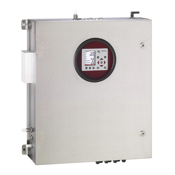
MRU GmbH SWG 100 User Manual Analyzer Description 2.1. Intended use The instrument is intended for analyzing the composition of syngases and determine the concentration of several components like CH4, CO2, O2 and H2. The instrument may optionally be equipped to monitor several sites in time sharing technique (cyclical one by one sampling). - Page 14 MRU GmbH SWG 100 User Manual Display (color, with backlight) Keypad Sample syngas inlet ports (1 to max 4 ), female G1/8” threads Cabinet lock Inlet cable glands M16 for I/O modules Inlet cable gland M16 for mains power supply Heat sink for gas cooler unit Condensate outlet port, female G1/8”...
-
Page 15: Principle Of Operation
MRU GmbH SWG 100 User Manual 2.2. Principle of operation • Sample gas from one or more sampling points is fed into the analyzer by dedicated ports. Internally mounted electric valves select one point at a time to feed sample gas to the analysis unit. -
Page 17: Marking And Range Of Application
MRU GmbH SWG 100 User Manual 2.3. Marking and range of application The analyzer is operating in a temperature range of - +45°C with intern cabinet heater. The specifications of the analyzer are: 230 VAC / 50 Hz Main power supply:... -
Page 18: Scope Of Supply And Delivery
MRU GmbH SWG 100 User Manual 3. Scope of supply and delivery The delivery contains the follow components: • Analyzer, with a stainless steel case. • A stainless-steel thread filter for the zero gas inlet, with a G1/8 inch male thread. -
Page 19: Material Required For The Installation (Not Scope Of Supply)
MRU GmbH SWG 100 User Manual 3.1. Material required for the installation (not scope of supply) Material for tubing or hosing the sample gas inlets and outlet. • For the sample gas inlets: Flexible PTFE tube or stainless steel tubing with a diameter of 4/6 mm. -
Page 20: Installation Manual
MRU GmbH SWG 100 User Manual Installation manual 4.1. Content of your order Your analyzer is delivered in a carton box and is protected with special edged protectors. Please do preserve the packing of your analyzer, for possible back shipment. -
Page 21: Steps For The Mechanical Mounting And Installation
MRU GmbH SWG 100 User Manual 4.4. Steps for the mechanical mounting and installation The graphic below shows the single steps, which must be done to mount the analyzer correctly into the application Mounting the analyser on a wall or a steel rack... -
Page 22: Mounting The Analyser On A Wall Or Steel Rack
MRU GmbH SWG 100 User Manual 4.5. Mounting the analyser on a wall or steel rack The analyzer can be mounted indoor or outdoor. The device is designed for the mounting on wall or on steel rack. The follow sketch shows the dimensions, which the analyzer needs for the correct mounting. - Page 23 MRU GmbH SWG 100 User Manual Distance, which should be fulfilled Min. 50 cm Min. 40 cm Do not cover the breather Min. 30 cm drain. For outdoor installation Ensure that the analyzer is mounted on a rain and sun protected place (weather shade).
- Page 24 MRU GmbH SWG 100 User Manual CAUTION Do not cover the breather drain! NOTE All connectors of the analyzer use female threads. The analyzer may be connected by tubing or piping. Top-side On the top of the analyzer are the sample gas-inlets. Sample gas inlet 1 is the default gas inlet port.
- Page 25 MRU GmbH SWG 100 User Manual Left-side CAUTION Be sure, that the heat sink has enough distance to the next wall. CAUTION Be sure that the Zero gas inlet feeds fresh, clean air. Heat sink: Do not cover the heat sink from the gas cooling- unit.
- Page 26 MRU GmbH SWG 100 User Manual Flow restrictor orifice (#65114) To measure any syngas applications, the analyzer can be equipped with a flow restrictor orifice (see picture). Male connector G1/8 Sinter filter Nozzle O-ring Picture: Flow restrictor orifice with intern filter.
-
Page 27: Installation Of The Power Supply
MRU GmbH SWG 100 User Manual 4.6. Installation of the power supply DANGER Explosion hazard Before start the mounting and installation work, make sure to have a certified flammable gas detector. DANGER Electric shock. Electricity may cause death. Only educated staff should be allowed for mounting and installation job. -
Page 28: Installation Of The External Switch-Off Circuit
MRU GmbH SWG 100 User Manual 4.7. Installation of the external switch-off circuit The remote power supply box itself is not explosion protected at all. Therefore it must be installed in safe area. WARNING Safety installation The external electric contactor K1 is a part of the safety installation. It is required to be installed by user when power supplying the analyser. - Page 29 MRU GmbH SWG 100 User Manual Page 29 of 143...
-
Page 30: Connection Of The I/O Module
MRU GmbH SWG 100 User Manual 4.8. Connection of the I/O module DANGER Explosion hazard Before start the mounting and installation work, make sure to have a certified flammable gas detector. DANGER Electric shock. Electricity may cause death. Only educated staff should be allowed for mounting and installation job. - Page 31 MRU GmbH SWG 100 User Manual Plug connector definition: WARNING Electric voltage Power the system down and protect for reconnecting, before start maintenance work. Slit screws Stripping length: 7 mm Tightening torque min.-max.: 0,5-0,6 Nm Conductor cross sections, which can be used: Type of electric line Conductor cross section min.-...
-
Page 32: Operation Of The Analyzer (Hmi)
MRU GmbH SWG 100 User Manual Operation of the analyzer (HMI) 5.1. Operating unit: Display and keypad NOTE Operation of the keypad is intrinsically safe. All commissioning can be carried out with the control-unit. The operating-unit can only be operated when the cabinet door is open. -
Page 33: Display And Keypad
MRU GmbH SWG 100 User Manual 6.1. Display and keypad All information required to operate the analyzer is displayed as shown below. Menu indication bar Function key bar Display area of - Menu SD-Card symbol - Indication green → read- and write access - Indication yellow →... -
Page 34: Analyzer Commissioning Manual
MRU GmbH SWG 100 User Manual Analyzer commissioning manual After the first start of the analyzer it is necessary to make some settings at the analyzer. These settings are: • Check the country and language. • Check the date and time of the instrument. -
Page 35: Configuration Of The Alarm Relays
MRU GmbH SWG 100 User Manual 7.3. Configuration of the alarm relays will turn the relay from NC to NO. Main board is offline (internal RS485 bus communication failure) Gas leakage inside analyzer cabinet (CH4 > 20% to 50% LEL) Condensate alarm (contacts resistance <... - Page 36 MRU GmbH SWG 100 User Manual Plug connector definition for the system alarm relay Slit screws Stripping length: 7 mm Tightening torque min.-max.: 0,5-0,6 Nm Conductor cross sections, which can be used: Type of electric line Conductor cross section min.- max.
-
Page 37: Configuration Of The Modbus
MRU GmbH SWG 100 User Manual 7.4. Configuration of the Modbus The Mobdbus connector can be found on the PCB-mainboard (see sketch below). NOTE: for specification of Modbus (RTU) data transfer over RS485, please observe appendix. User RS-485 (Modbus RTU) - Page 38 MRU GmbH SWG 100 User Manual Configuration at the analyzer 1. Open the path XTRAS ENERAL ETTINGS 2. Press 3. The Modbus store settings will be open. The user can commission the slaves settings. The following settings can be set: •...
-
Page 39: Configuration Of The External Control (Option: Io Module)
MRU GmbH SWG 100 User Manual 7.5. Configuration of the external control (Option: IO module) This feature requires an I/O module (optional) and the function must be activated This feature can be used for the external control of the analyzer. With the help of the external control follow operations can be done: •... - Page 40 MRU GmbH SWG 100 User Manual Connection of the external control via 4-20 mA input signals The signal inputs built a 4-bit binary number: I4 I1: 0-11 mA=open=0; 11/12-20 mA=closed=1. Connection of the external control via one 4-20 mA input signal The user has the opportunity to control the analyzer with only the first 4-20mA input (see sketch below).
- Page 41 MRU GmbH SWG 100 User Manual Configuration at the analyzer Open the path: XTRAS ENERAL SETTINGS 2. Switch the menu- Relais (dependent from the connected signal input.). When the external control is activated an arrow symbol will appear at the title line.
- Page 42 MRU GmbH SWG 100 User Manual Case 2: External control of a sample point -Zeroing: First the zeroing will be done. The duration of the zeropoint can be set at the menu ext. configurated at the analyzer -Gas sampling: The gas sampling is for purging the entire system and give the analyzer enough configurated at time for response.
-
Page 43: Configuration Of The Analog Outputs At The I/O Module
MRU GmbH SWG 100 User Manual 7.6. Configuration of the analog outputs at the I/O module Each I/O module provides 4 channel analog 4-20mA outputs, which are able to provide the measuring values via 8 wire cable to a remote PLC or DCS. -
Page 44: Configure Alarm Output Of I/O Module
MRU GmbH SWG 100 User Manual 7.7. Configure alarm output of I/O module Each I/O module provides 2 alarm relay contacts (see previous page) normally open contacts (fail safe type) which will send alarm status via 4 wire cable to a remote PLC or DCS. - Page 45 MRU GmbH SWG 100 User Manual Test the alarm outputs of the IO module Use the menu XTRAS LARM UTPUT ONFIGURATION Open the submenu The following screenshot will appear. With all alarm outputs in the entire analyzer can be activated.
-
Page 46: Configure The Aux-Input On Software-Side
MRU GmbH SWG 100 User Manual 7.8. Configure the AUX-input on software-side: Open the menu point AUX input configuration which can be found under the path / AUX XTRAS INPUT CONFIGURATION 2. All possible inputs are listed in the following screen. Every IO module is able to load four signals. -
Page 47: Configuration Of The Ethernetmodule
MRU GmbH SWG 100 User Manual 7.9. Configuration of the ethernetmodule • The following screen will appear. Select Z-Key at the register called • Page 47 from 143... - Page 48 MRU GmbH SWG 100 User Manual The following current IP-address, which is saved at the module will appear. USB-port of a pc. Then t The settings will be written to the module. Page 48 from 143...
- Page 49 MRU GmbH SWG 100 User Manual ATTENTION It can happen that the following message will appear: Just confirm the message and test, whether the settings are set. Normally the message can be ignored. 5. The settings are saved at the module now.
- Page 50 MRU GmbH SWG 100 User Manual F3=Modbus 2. Open the path Extras/General settings, at the analyzer. Push At this menu the modbus slave parameters can be configurated. Example: Baud rate: 19200 Slave address: 238 Stop bits: 1 Parity: even Data bits: 8 Picture: The screenshot shows an example of a Modbus slave settings.
- Page 51 MRU GmbH SWG 100 User Manual appeared. At this protocol the following adjustments must be set: 6. Working mode: MODBUS BRIDGE ON PORT#2 (1). 7. Baudrate (2): 8. Data Bits (2). 9. Parity (2). Page 51 from 143...
- Page 52 MRU GmbH SWG 100 User Manual 10. Stop Bits (2). • • The baudrate, data bits, parity and stop bits must be the same like at the SWG100. Page 52 from 143...
- Page 53 MRU GmbH SWG 100 User Manual Connection the SWG100 with MRU4WIN 1. Open MRU4WIN. 3. Set the Modbus setting from Serial to TCP(2). Can be found at the webserver Here the type of the device must be set. Example: It is the...
-
Page 54: Mounting And Installation Of The Gas Cylinders For The Auto Calibration
MRU GmbH SWG 100 User Manual 9.1. Mounting and installation of the gas cylinders for the auto calibration function Mounting and installation of the gas cylinders for the auto calibration function The auto calibration function allows the calibration of the analyzer. To use the auto calibration function, it is necessary to install the calibration gas bottles on the analyzer. - Page 55 MRU GmbH SWG 100 User Manual Software side: Adjustment for the option auto-calibration: from XTRAS DJUSTMENT MENU ETUP AUTO ” CALIBRATION 2. Select to set the gas composition from the calibration gas cylinder Arrow keys left/ right: With these keys the gas composition can be set.
- Page 56 MRU GmbH SWG 100 User Manual NOTE All gas concentrations are in percent! The factor from percent to ppm is: 1% = 10.000 ppm! 5. The user has the following options: - leave the menu: The set gas concentrations are stored and the auto calibration will start after the interval is reached.
-
Page 57: Cycle Configuration
MRU GmbH SWG 100 User Manual 10.1. Cycle configuration Path and default setting XTRA EASUREMENT CYCLE CONFIG When the menu is selected the user definable setting for the EASUREMENT CYCLE CONFIG measurement cycle will appear (see screenshot below). Screenshot shows default setting, when the will be started the first „M... - Page 58 MRU GmbH SWG 100 User Manual The two auto-configurations, which can be selected. Depending on the analyser type, the first or the first and second phase cannot be deleted, deactivated or moved to another position. Delete a phase With a phase can be deleted. To do this, select the phase, which should be deleted and press Screenshot shows how a phase can be deleted.
- Page 59 MRU GmbH SWG 100 User Manual Zeroing (Cycle phase details): he zeroing time can be EROING configured. ZEROING Measuring site valves Valves closed Zeroing valve Valve open Duration 2min to 1 h Recommendation 5min., in general not to be changed by user as...
- Page 60 MRU GmbH SWG 100 User Manual • Phase duration: Entire Stand-by time (Purging time + Quiet time = Phase time). • Purging time: The time, to purge the analyser with ambient air, through the zero gas inlet. • Quiet time: The time, where the analyser is in the pure stand-by mode.
- Page 61 MRU GmbH SWG 100 User Manual Example for a measurement cycle configuration In this chapter an individual measurement cycle should be created with the features described at the chapters below. The measurement cycle should have the following sequence: Following points must be done to configure the individual measurement cycle: 1.
- Page 62 MRU GmbH SWG 100 User Manual Open with the key the cycle phase detail of the measurement SP2. Adjust the duration-phase at 15 min. and the suction/response time until the pure meas. time has the value of 3 min. Use for this operation the...
-
Page 63: Administrator Pin Code
MRU GmbH SWG 100 User Manual Leave the menu and safe the adjustments. The individual configuration is done. Administrator PIN code All functions and menus which may disturb the analyzer's normal measurement can be protected against unauthorized access by activating the administrator PIN code request. -
Page 65: Operating The Analyzer
MRU GmbH SWG 100 User Manual 11. Operating the analyzer This chapter has the follow structure: • In the first part it will be explained, how to start the analyzer and the selftest menu. • Part three shows the submenu, which are listed at the EXTRA menu. - Page 66 MRU GmbH SWG 100 User Manual Self-Test The first menu to be displayed after Power-On is the self-test menu. The analyzer won't leave this menu before all sub-systems will be connected and the gas cooler (option) has reached the target operation temperature.
- Page 67 MRU GmbH SWG 100 User Manual For devices with just one measuring point the switching is additional possible with the arrow keys up / down. Change the displayed page Use the arrow keys left / right can be changed in both display modes the page. The new page number is displayed in the title bar for a moment just after the successful change.
-
Page 68: Data Storage Menu
MRU GmbH SWG 100 User Manual 11.2. Data Storage Menu The data storage menu can be reached by pressing 'storage' in the measurement menu: The menu provides an overview of stored measurements of each sample point and of the memory usage. - Page 69 MRU GmbH SWG 100 User Manual General information about the data storage Data storage strategy is as follows: • The analyzer may store up to 20,000 measurement points (including all relevant data). • At the end of each measurement cycle (per sampling point) the current values will be stored.
- Page 70 MRU GmbH SWG 100 User Manual The CSV format is not exactly the same in all countries. The analyser selects a fitting format variation according to the selected country. Nevertheless the CSV output can be changed the Data Storage Menu.
-
Page 71: Extra Menu: Overview
MRU GmbH SWG 100 User Manual 11.3. Extra menu: Overview General settings Measurement configuration Measurement cycle config. Analog output configuration Alarm output configuration Adjustment menu Default settings Content SD card Even viewer Device info General settings Path: XTRA ENERAL SETTINGS... - Page 72 MRU GmbH SWG 100 User Manual Measurement configuration Path: XTRA EASUREMENT CONFIGURATION Structure: Measurement configuration Extras/Measurement configuration Measurement configuration Temperature °C or °F / default °C Pressure hPa, mbar or mmHG / default hPa Sample flow 30 l/h...60 l/h / default 50 l/h / steps: 5 l/h Measurement cycle config.
- Page 73 MRU GmbH SWG 100 User Manual Adjustment menu Path: XTRAS DJUSTMENT MENU Structure: Device info Extra/Adjusment menu Adjusment gas factor (see service manual) Adjusment gas nom. Value (see service manual). NDIR CO2/CH4 adjustment Averaging (see Averaging in this chapter). Adjustment CH4 pellistor (see service manual) Hardware state &...
- Page 74 MRU GmbH SWG 100 User Manual Hardware state & tests: Page 74 from 143...
- Page 75 MRU GmbH SWG 100 User Manual Number Hardware Settings Gas pump ON or OFF Purge pump (optional) ON or OFF Solenoid valve H2S low (optional) ON or OFF Solenoid valve zero gas ON or OFF Solenoid valve cal. Gas ON or OFF...
- Page 76 MRU GmbH SWG 100 User Manual NOTE Effect of the average time A smooth averaging time smooths the measurement signal but increase the response time of the measurement signal. Page 76 from 143...
- Page 77 MRU GmbH SWG 100 User Manual Default configuration Use the menu for the default configuration: -> E > D EASUREMENT XTRAS EFAULT ETTINGS DEFAULT CONFIGURATION Analog output 4- Parameter 20mA Alarm output relay contact 20mA open CH4 [ % ]...
- Page 78 MRU GmbH SWG 100 User Manual Contents SD card Path: XTRAS CONTENT CARD Structure: Contents SD card Extras/Contents SD card General settings Overview of the stored datas on the SD card. Skip the cursor on the first position. Open the file. User can view the stored screenshots.
- Page 79 MRU GmbH SWG 100 User Manual Device info Path: XTRAS EVICE INFO Structure: Main device info Device info Extra/Device info Main device info detail Sub systems info MAINBOARD Sub systems info NDIR bench Sub systems info I/O module 1-max. 10...
- Page 80 MRU GmbH SWG 100 User Manual Power-Down of analyzer Before the analyzer is disconnected from mains, it should be prepared for the Power-Down, because • operational data should be stored • eventually changed user settings should be stored • the sensors should be purged with fresh air...
-
Page 81: Power Up And Commissioning The Analyser
MRU GmbH SWG 100 User Manual Power up and commissioning the analyser After installation of the analyzer few steps should be processed in order to operate the instrument properly. The graphic below shows the few steps, which should be done, to power up the analyser correctly. -
Page 82: Power Up The Analyser
MRU GmbH SWG 100 User Manual 12.1. Power up the analyser 1. Open the case door of the analyser. 2. Power up the circuit breaker. See figure below. Power up the circuit breaker. 3. Press the power switch of the remote power supply box. Wait until the system is ready for operation. -
Page 83: Check Country And Language
MRU GmbH SWG 100 User Manual 12.2. Check country and language Important note: In case the analyzer shows a language, you don't understand, you may swap the language to English by pressing the menu key and selecting the function 'Set English language'. -
Page 84: Configuration Of The Alarm Relays
MRU GmbH SWG 100 User Manual 12.5. Configuration of the alarm relays ontact. The following errors will turn the relay from NC to NO. Main board is offline (internal RS485 bus communication failure) Gas leakage inside analyzer cabinet (CH4 > 20% to 50% LEL) Condensate alarm (contacts resistance <... - Page 85 MRU GmbH SWG 100 User Manual Plug connector definition for the system alarm relay Slit screws Stripping length: 7 mm Tightening torque min.-max.: 0,5-0,6 Nm Conductor cross sections, which can be used: Type of electric line Conductor cross section min.- max.
-
Page 86: Configuration Of The Modbus
MRU GmbH SWG 100 User Manual 12.6. Configuration of the Modbus The Mobdbus connector can be found on the PCB-mainboard (see sketch below). NOTE: for specification of Modbus (RTU) data transfer over RS485, please observe appendix. User RS-485 (Modbus RTU) - Page 87 MRU GmbH SWG 100 User Manual Page 87 from 143...
-
Page 88: Configuration Of The External Control (Option: Io Module)
MRU GmbH SWG 100 User Manual 12.7. Configuration of the external control (Option: IO module) This feature requires an I/O module (optional) and the function must be activated This feature can be used for the external control of the analyzer. With the help of the external control follow operations can be done: •... - Page 89 MRU GmbH SWG 100 User Manual Connection of the external control via 4-20 mA input signals The signal inputs built a 4-bit binary number: I4 I1: 0-11 mA=open=0; 11/12-20 mA=closed=1. Connection of the external control via one 4-20 mA input signal The user has the opportunity to control the analyzer with only the first 4-20mA input (see sketch below).
- Page 90 MRU GmbH SWG 100 User Manual Configuration at the analyzer Open the path: XTRAS ENERAL SETTINGS 5. Switch the menu-poi Relais 4x mA (dependent from the connected signal input.). When the external control is activated an arrow symbol will appear at the title line.
- Page 91 MRU GmbH SWG 100 User Manual -Measurement: The measurement will be started after the response/ suction time is finished. It will be only abort, if the user changes the status of the external signal sources. The chart below shows the possible statues, which can be set at the analyzer:...
-
Page 92: Configuration Of The Analog Outputs At The I/O Module
MRU GmbH SWG 100 User Manual 12.8. Configuration of the analog outputs at the I/O module Each I/O module provides 4 channel analog 4-20mA outputs, which are able to provide the measuring values via 8 wire cable to a remote PLC or DCS. -
Page 93: Configure Alarm Output Of I/O Module
MRU GmbH SWG 100 User Manual 12.9. Configure alarm output of I/O module Each I/O module provides 2 alarm relay contacts (see previous page) normally open contacts (fail safe type) which will send alarm status via 4 wire cable to a remote PLC or DCS. - Page 94 MRU GmbH SWG 100 User Manual Test the alarm outputs of the IO module Use the menu XTRAS LARM UTPUT ONFIGURATION Open the submenu The following screenshot will appear. With all alarm outputs in the entire analyzer can be activated.
-
Page 95: Configure The Aux-Input On Software-Side
MRU GmbH SWG 100 User Manual ATTENTION With the test modus for the alarm outputs of the IO module, the alarm relays at the IO modules and the relay at the PCB mainboard can be activated. 12.10. Configure the AUX-input on software-side:... - Page 96 MRU GmbH SWG 100 User Manual arrow keys. The measurement item can be named by the user. To set the measurement unit rotates with the left/ right arrow keys. 5. Important for the AUX-inputs is the measurement range. The range is set with 6.
-
Page 97: Operating The Analyser
MRU GmbH SWG 100 User Manual Operating the analyser 13.1. Administrator PIN code All functions and menus which may disturb the normal measurement can be protected against unauthorized access by activating the administrator PIN code request. We highly recommend activating this function, when unauthorized persons could access the analyzer. -
Page 98: Main Menu Measurement
MRU GmbH SWG 100 User Manual 13.4. Main menu measurement This menu is the root of all menus and will be shown automatically as soon as the self-test is finished. The title bar you can see on the left the current measurement... - Page 99 MRU GmbH SWG 100 User Manual Manual zeroing and selection of measurement points For analyzers with just one measuring point, the status of "measuring" by pressing the F1 key = "zero" will be canceled and the next manual zeroing be initiated.
-
Page 101: Data Storage
MRU GmbH SWG 100 User Manual 13.5. Data Storage The analyser makes use of an internal flash memory to store measurement values automatically. Data storage strategy is as follows: • The analyser may store up to 20,000 measurement points (including all relevant data). -
Page 102: Power-Down Of Analyzer
MRU GmbH SWG 100 User Manual When entering the menu the measurements of the last 24 hours will be displayed. This interval can be changed by pressing the keys F1=more or F3='less'. Export of measurements to SD card This function is used to export the measurements from the analyzer to a PC. The used format is CSV (comma-separated values). - Page 103 MRU GmbH SWG 100 User Manual Note: You also may enter this menu by pressing the OFF key and leave it by pressing the ESC key (without starting the purge cycle) , when you just want to store operational data and user settings.
-
Page 105: Backup/Restore All Individual User-Settings
MRU GmbH SWG 100 User Manual 13.7. Backup/restore all individual user-settings It's a quite amount of work to configure the analyzer, especially when the analyzer provides several sample points and several IO-modules and when the analog ouputs are used. Therefore, we recommend to backup all your found settings on the SD card. -
Page 107: Update The Firmware
MRU GmbH SWG 100 User Manual 13.9. Update the firmware DANGER Explosion hazard all time the ambient atmosphere with a certified flammable gas detector. The analyzer and different installed options can be updated, if it is necessary. Following options can be updated: •... - Page 108 MRU GmbH SWG 100 User Manual Update the analyzer (Firmware- 1. Open the path: XTRA EVICE F2 = details 2. Press to open the details for the main device menu. F2 = FW update 3. Press . The analyzer will start the update from the SD-card.
- Page 109 MRU GmbH SWG 100 User Manual 4. The Update will start from the SD-card, if a firmware with the filename -card. Update the IO modules (Firmware- Open the path: XTRA EVICE INFO F3 = sub.syst 2. Press UB SYSTEMS INFO F2 = details 3.
-
Page 110: Service And Maintenance
MRU GmbH SWG 100 User Manual Service and maintenance DANGER Explosion hazard all time the ambient atmosphere with a certified flammable gas detector. CAUTION The maintenance part is important to guarantee, that the analyser works correctly and the entire system is safely. -
Page 111: Regular Maintenance Works By The Operator
MRU GmbH SWG 100 User Manual 14.2. Regular maintenance works by the operator All inspections- and maintenance works are dependent from individual operating conditions, and site. The specified intervals below are only benchmarks. Review Recommended Actions intervals Moisture in the analyzer. -
Page 112: Position And Overview Of The Service-Parts
MRU GmbH SWG 100 User Manual 14.3. Position and overview of the service-parts Page 112 from 143... - Page 113 MRU GmbH SWG 100 User Manual Content of the service-set (offer-number: 66174) Single components can be offered under their article number directly. Interval Image name Quantity Offer-number New state: purple beads Acid-gas filter Used: white beads 2 pieces 56795 Life time: 2-6 month, dependend from gas concentration.
- Page 114 MRU GmbH SWG 100 User Manual Position 1: Acid-gas filter (#56795) Required materials 2x Acid gas filter (#56795), contained in the service- set. Required tools: Needle-nose pliers. Exchange interval: Exchange necessary, if filter turns from purple to white. Steps: Remove exhausted acid gas filter from...
- Page 115 MRU GmbH SWG 100 User Manual Position 2 and 3: Dust- and particle filter (#65533 and #66088) Required materials : Dust- and particle filter (#65533 and #66088) contained in the service set. Required tools: needle-nose pliers. Exchange interval: Exchange necessary, if the filter gets dark or black.
- Page 116 MRU GmbH SWG 100 User Manual Position 4: PTFE Filter (#51513) Required materials: PTFE filter (#51513) contained in the service set. Required tools: needle-nose pliers. Exchange interval: Exchange necessary, if gas flow is too low. Steps: Pull the exhausted filter-unit from the viton tube and exchange it with a new one.
-
Page 117: Cleaning The Surface Of Swg100
MRU GmbH SWG 100 User Manual 14.4. Cleaning the surface of SWG100 DANGER Explosion hazard For cleaning the cabinet uses a wet and antistatic cloth to prevent electrostatic charge. The analyzer is designed for explosive atmosphere class 2. If the cabinet and the window must be cleaned, it is necessary to use a wet and antistatic cloth to prevent an electrostatic charge of the cabinet. -
Page 119: Exchange Of Electrochemical Sensors
MRU GmbH SWG 100 User Manual Exchange of electrochemical sensors The position of the electrochemical sensor in the SWG-100 SYNGAS is shown in the sketch below. Depending form the design of the electrochemical sensors design, there are different ways to exchange the sensor. - Page 121 MRU GmbH SWG 100 User Manual Exchange the sensors of the model A Required sensor: O2-Sensor (65824 position 1) CAUTION Do not disposal the sensor in the domestic waste! Exhausted chemical sensors are special waste! To exchange the sensor, following steps must be done: Unplug the sensor connection cable here •...
- Page 122 MRU GmbH SWG 100 User Manual Exchange the sensors of the model B Affected sensors: H2S low Sensor (65825 position 2) H2 low sensor (65827 position 4). CAUTION Do not disposal the sensor in the domestic waste! Exhausted chemical sensors are special waste! To exchange the sensors, following steps must be done: •...
- Page 123 MRU GmbH SWG 100 User Manual Exchange the sensors from the model C Affected sensors: H2S high sensor (65826 position 2) H2S sensor (66060 position 4). CAUTION Do not disposal the sensor in the domestic waste! Exhausted chemical sensors are special waste! To exchange the sensors, following steps must be done: •...
-
Page 125: Analyzer Calibration
Once in a while it is necessary to recalibrate the analyzer. The exact interval time depends on the syngas condition (gas concentration, total measuring time) and shall be determined by the user. MRU recommends at least half yearly calibration. Calibration is carried out by connecting certified gas cylinder to the analyzer. As... - Page 126 MRU GmbH SWG 100 User Manual Troubleshooting Error Possible causes Solutions Display does not work. - System is not power-up. - connect main power supply. - power up automatic fuse. contact customer support. Analyzer powers down by - The fan is defect.
-
Page 127: Technical Specification
MRU GmbH SWG 100 User Manual Technical specification Allgemein General Deutsch Angabe English Betriebstemperatur (ohne +5°C ... +45 °C / 41 °F ... Operating temperature Frostschutzheizung) 113 °F (without heating) Betriebstemperatur (mit optionaler -20 °C ... +45°C / 14 °F... - Page 128 MRU GmbH SWG 100 User Manual Tastatur mit Anzahl Tasten Keyboard with qty of keys Elektrische Aus- /Eingänge Electrical I/O Serielle Schnittstelle RS485 Serial interface Protokoll Modbus RTU Protocol Typ Analogausgang 4 ... 20 mA Type of analog output Anzahl Ausgangskanäle...
- Page 129 MRU GmbH SWG 100 User Manual Jahre erwartete Lebensdauer an Luft Years expected lifetime (@air) Elektrochemischer Sensor H2S low200 Electrochemical Sensor Messbereich 0-200 ppm Measuring Range Auflösung 1 ppm Resolution Überlastbereich < 1000 ppm Overload Range ±5 ppm / Genauigkeit abs.
- Page 130 MRU GmbH SWG 100 User Manual Ansprechzeit T90 < 40s Response Time T90 Jahre erwartete Lebensdauer an Luft (abhängig von Years expected lifetime (@air) gewähltem Sensor) (Depending on chosen sensor) Elektrochemischer Sensor Electrochemical Sensor Nominaler Messbereich 0-1000 ppm Nom. Measuring Range Überlastbereich...
-
Page 131: Declaration Of Conformity
MRU GmbH SWG 100 User Manual Declaration of conformity Page 131 from 143... - Page 132 MRU GmbH SWG 100 User Manual Page 132 from 143...
-
Page 133: Appendix
MRU GmbH SWG 100 User Manual APPENDIX 18.1. General information The Modbus/Profibus Slave function requires the analyser firmware version V1.11.00 dated 12.07.2016 or later. Multi byte values are transmitted in Motorola ® byte order (Big-Endian). Only ® the CRC16 at the end of each frame is transmitted in Intel... -
Page 134: Special Informationen About The Profibus Slave Function
SWG 100 User Manual 18.3. Special informationen about the Profibus Slave function • The Profibus Slave function requires a modbus/profibus-converter "Seneca HD67561", which is configured and installed in the analyser. • Usually MRU sets the Profibus ID to 84. Page 134 from 143... -
Page 135: Defined Registers To Be Read By The Master
MRU GmbH SWG 100 User Manual 19. Defined registers to be read by the master modbus profibus data register content address address type Status & Device info Analyser Status (more details read below) System Alarm (more details read below) Serial number... - Page 136 MRU GmbH SWG 100 User Manual modbus profibus data register content address address type Net calorific value [MJ/m³] Gross calorific value [MJ/m³] CO [ppm] (optional) CH4 [ppm] (optional, when CH4 [%] also available) CO2 [ppm] (optional, when CO2 [%] also...
- Page 137 MRU GmbH SWG 100 User Manual Net calorific value [MJ/m³] Gross calorific value [MJ/m³] CO [ppm] (optional) CH4 [ppm] (optional, when CH4 [%] also available) CO2 [ppm] (optional, when CO2 [%] also available) not (yet) defined (reads zero) Status & measurement values of sample point 3-10 (optional)
- Page 138 MRU GmbH SWG 100 User Manual AUX-value read by IO-module 4 - Input 2 AUX-value read by IO-module 4 - Input 3 AUX-value read by IO-module 4 - Input 4 AUX-value read by IO-module 5 - Input 1 AUX-value read by IO-module 5 -...
-
Page 139: Analyser Status (Address 0 And Some Mirror Addresses)
MRU GmbH SWG 100 User Manual 19.1. Analyser Status (address 0 and some mirror addresses) The Analyser Status is a 32bit-word and must be interpreted bitwise. Description Power-On (until the first zeroing has been done) System-Alarm, see table below Air Purging (zeroing) -
Page 140: Analyser System Alarm (Address 2 And Some Mirror Addresses)
MRU GmbH SWG 100 User Manual 19.2. Analyser System Alarm (address 2 and some mirror addresses) The Analyser System Alarm is a 32bit-word and must be interpreted bitwise. Meas. Description halted Mainboard Offline (some communication problems) Mainboard is in bootloader mode CH4 ambient >... -
Page 141: Spare Parts List
MRU GmbH SWG 100 User Manual 19.3. Spare parts list Article Description – Serial number Condensate pump - #11230 Required to drain the condensate Sample gas pump - #65032 Used for sample gas pumping H2S solenoid valve - #65470 Required for cut-off sample gas supply to sensor. - Page 142 MRU GmbH SWG 100 User Manual Display and operation unit #65133 Control unit for the user. I/O-Module #65179 + #65430 Used for analog output data transfer and sample point switching. I/O Module - #65179 Used for analog output data transfer...
- Page 143 MRU GmbH SWG 100 User Manual Technical data change w/o notice Date of issue: REV01 20180820 Page 143 of 143...
Need help?
Do you have a question about the SWG 100 and is the answer not in the manual?
Questions and answers