mru OPTIMA 7 User Manual
Hide thumbs
Also See for OPTIMA 7:
- User manual (51 pages) ,
- User manual (76 pages) ,
- User manual (76 pages)
Table of Contents
Advertisement
Advertisement
Table of Contents
Troubleshooting

Related Manuals for mru OPTIMA 7


Summary of Contents for mru OPTIMA 7
- Page 1 USER MANUAL OPTIMA 7 1 / 78 MRU GmbH, D-74172 Neckarsulm...
- Page 2 USER MANUAL OPTIMA 7 Producer: Legal notices / Intellectual property rights comments Original user manual © 2020 by MRU No part of this manual my be published in any form (print, fotocopy, electronic media or any other publication form) without a written approval by the publisher.
-
Page 3: Table Of Contents
USER MANUAL OPTIMA 7 Table of content Information for product and safety ..........6 1.1. Safety manual ....................6 1.2. Safety precautions ..................6 Ensure safety ....................7 Important general information about the device ......7 1.5. User guideline for rechargeable batteries ..........8 Introduction .................. - Page 4 USER MANUAL OPTIMA 7 Ensure power supply ................. 32 Automatic Auto-off function ..............32 Measuring with grid power supply / Battery charging ....32 Battery charge condition ................. 32 Operating temperature ................33 Controlling Condensate separator (water trap) ....... 33 Connections and tightness ..............
- Page 5 USER MANUAL OPTIMA 7 Exporting differential pressure measurements........56 Measurement in Data storage ............... 56 Viewing measurements ..................56 Deleting measurements ................... 57 Transferring measurements to SD-Card (Option) ........58 Extras / Adjustment ............... 59 9.1. Service calibration menu ................. 59 Default settings ...................
-
Page 6: Information For Product And Safety
USER MANUAL OPTIMA 7 Information for product and safety 1.1. Safety manual All general information and safety precautions of MRU products are listed in the supplied separate safety manual. Therefore, this manual must be read and observed before the first use of the instrument . -
Page 7: Ensure Safety
USER MANUAL OPTIMA 7 Ensure safety ► Please read the user manual completely before the first use. ► Only use the analyzer for the intended use and within the parameters specified in the technical data. ► Do not use any violence. -
Page 8: User Guideline For Rechargeable Batteries
USER MANUAL OPTIMA 7 • The battery life is at least 500 charge-discharge cycles. With increasing number of charging cycles the battery ca- pacity (indicated in operating hours) is reduced. 1.5. User guideline for rechargeable batteries NOTE The rechargeable batterie is installed inside the ana- lyzer and is not accessible to the end customer. -
Page 9: Introduction
USER MANUAL OPTIMA 7 2 Introduction • This manual enables you to understand and safely operate this MRU Analyzer. • Please read this manual with great vigilant and get familiar with the product before using it. • This analyzer may only be operated by competent personnel and for its intended use. -
Page 10: About Us
USER MANUAL OPTIMA 7 About us The analyzer is produced by the MRU GmbH in Neckarsulm, Germany (Founded in 1984), a medium sized company that specializes in devel- oping, producing and marketing high quality emission monitoring analyzers. MRU GmbH produces a wide range of instruments, from standard analyzers up to tailor made industrial analyzers. -
Page 11: Packaging
Hazardous waste must be returned to MRU prepaid. Return of electronic equipment MRU GmbH is required to accept the return, for proper disposal, of all analyzers delivered after 13th of August 2005. Analyzers must be re- turned to MRU prepaid. -
Page 12: Description
Available options for this and other analyzers can be found on the MRU Homepage or speak to a member of our sales team. Gas schematics diagram... -
Page 13: The Analyzer
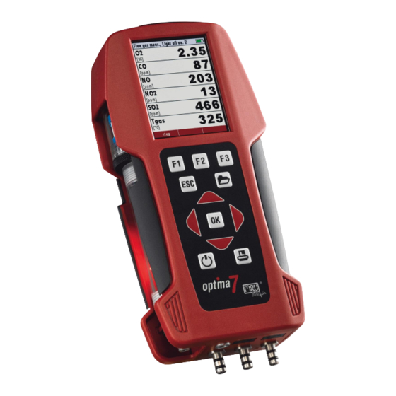
USER MANUAL OPTIMA 7 3.2. The Analyzer The compact analyzer is made from a fibre re-enforced plastic material with all measurement related connections at the bottom of the analyzer. Position Description Display Key pad Temperature connector T2 Temperature connector T1... -
Page 14: The Condensate Separator (Water Trap)
Remove the condensate separator by pulling it towards you (1) out of the groove of the OPTIMA 7 housing, then pull it downwards (2). Condensate vessel and plugs are screwed together. To change the filter and dry and clean the condensate separator this can be easily disassem- bled and screwed together again. -
Page 15: Extraction Probes
USER MANUAL OPTIMA 7 3.4. Extraction probes The analyzer is available with either a probe with fixed probe tube or with ex- changeable probe tubes. A complete list of available probe options can be found in our effective price list. -
Page 16: Operating
USER MANUAL OPTIMA 7 4 Operating Display All information required to operate the analyzer is displayed as shown below. Position Description Menu bar Function key bar Display panel 1. Menu 2. Measurement value Zeroing active SD-Card in the slot 1. Indication green... -
Page 17: Keypad
USER MANUAL OPTIMA 7 Keypad Description and function of the keys: Press to start the analyzer without delay. The power off function will be delayed to protect the sensors. If ON/OFF there is not enough ambient air the analyzer will recommend the purg- ing of the sensors. -
Page 18: Menu Structure
USER MANUAL OPTIMA 7 Menu structure The analyzer organizes all available actions in three main menus: • Menu Measurement All available measurement options will be displayed and can be se- lected here. • Menu Storage All available storage options will be displayed and can be selected here. -
Page 19: First Usage
USER MANUAL OPTIMA 7 5 First usage After the analyzer has been inspected and is ready for start-up it can be switched on and personalized settings can be entered. These settings can be changed at any time. 5.1. Preparatory steps ►... -
Page 20: Setting Measurement
USER MANUAL OPTIMA 7 Setting Range Description LCD brightness 5 – 100 % Display-brightness, depending on temperature and also on the per- sonal judgement of the user, at 20°C a value of ca. 50% is normal Language option Select device languages... - Page 21 USER MANUAL OPTIMA 7 In the "Measurement settings" menu you can make for example the fol- lowing adjustments: Temperature Unit °C, °F Change the unit for temperature in all screens Pressure Unit Pa, hPa/Pa, hPa, Change the unit for pressure in all kPa/Pa, kPa, screens.
-
Page 22: Power-On Protection
The menu print-out appears. In the menu "print-out" menu you can make for example the following adjustments: Printer type Select printer type MRU / HP Print logo ON/OFF Print logo Print option SHORT: Print-out without area for signature and site in-... -
Page 23: Setting Bluetooth Parameters
► Press F3. The menu Settings appears. ► Press F2. The menu Bluetooth appears. The following MRU software can be used: MRU4u (Bluetooth) Available in the Apple App Store and Google Play For iOS communication with PC, tablet or smartphone... -
Page 24: Bluetooth Module Default Setting
USER MANUAL OPTIMA 7 For further information please refer to the corresponding documenta- tion for the respective software program Bluetooth module Default setting A default setting is required if the BT name is not displayed in the mo- bile phone. - Page 25 USER MANUAL OPTIMA 7 ► Press the Menu Key. A selection list appears. ► Select Default settings. ► Press OK. The BT module is set to default settings A message appears. ► Power down the analyzer. ► Wait 10 seconds until you power on the analyzer again.
-
Page 26: Setting Date And Time
USER MANUAL OPTIMA 7 Setting date and time The analyzer has an automatic changeover from summer to winter time. If the built-in rechargeable battery is completely discharged, a new setting of these values is required ► Press F3. The Extra menu appears. -
Page 27: Setting Co Limit Value
USER MANUAL OPTIMA 7 Setting CO limit value High CO concentrations in the gas stream can shorten the life span of your CO sensor. The analyzer can warn the user if the analyzer exceeds a pre-defined CO limit. ► Select Gas measurements. -
Page 28: Setting O 2 Reference
USER MANUAL OPTIMA 7 ► Select Gas measurements. ► Press OK. The menu Selection meas. program appears. ► Press OK The menu Fuel type selection appears. ► Press F2. The menu Fuel type list appears. ► Select the fuel which should be added to the menu Fuel type selec- tion. -
Page 29: Defining User Fuels Type
USER MANUAL OPTIMA 7 Defining user fuels type NOTE Note that you can only set the fuel type selection and O2 reference if the combustion calculation has been switched on. See also Chapter 5.3 Setting measurement, Page You can define four fuels to your individual needs. -
Page 30: Defining Measurement Window
USER MANUAL OPTIMA 7 ► Select the desired fuel parameter. ► Change the desired fuel parameter. ► Press OK. The defined user fuel appears in the menu Fuel type list. You can add the defined user fuel to the menu Fuel type selec- tion. -
Page 31: Configuring Zoom Window
USER MANUAL OPTIMA 7 Configuring zoom window Three zoom windows are available in each measuring program for the zoomed display of 2 measured values each. Which values are displayed zoomed is configurable. ► Start a measuring program. In this example Programm1, Natural gas. -
Page 32: Preparing Measurement
USER MANUAL OPTIMA 7 6 Preparing measurement Ensure power supply The analyzer can be used with: • with the internal MRU battery (provided) • with the MRU battery charger (provided) External equipment may only be connected while the analyzer is switched off! Automatic Auto-off function The instrument is automatically switched off after 60 minutes. -
Page 33: Operating Temperature
USER MANUAL OPTIMA 7 Operating temperature If the analyzer has been stored at low temperatures, it will require some time to equilibrate to the ambient temperature before being switched on. If it does not equilibrate, condensation will occur inside the analyzer! If the temperature is out of its operation range you will see the follow- ing messages on the display: “Analyzer too hot”... -
Page 34: Connections And Tightness
USER MANUAL OPTIMA 7 Connections and tightness Check all plug connections for correct fitting. Check all hoses, hose connections, condensate containers (from the probe tip to the gas connection on the analyzer) for tightness. The analyzer has a built-in automatic test to check the tightness of the gas paths. -
Page 35: Performing Measurement
USER MANUAL OPTIMA 7 7 Performing measurement In the basic configuration, each analyzer has the complete functionality you need for gas measurement. The process of gas measurement is described below. The description of other optionally available measuring programs can be found in the appendix or on separate supplementary sheets. -
Page 36: Core Flow Search
USER MANUAL OPTIMA 7 ► Go to the Measurement menu. ► Press OK. The menu Selection meas. program appears. ► Select the desired measurement program. ► If necessary, change the CO limit. See also Chapter 5.10 Setting CO limit value, Page 27. -
Page 37: Measured Value Display
USER MANUAL OPTIMA 7 Before using the core flow search it must be switched-on: Positioning the probe in the core flow: Insert the probe pipe slowly into the stack and position your probe pipe when you have reached the maximum flue gas temperature that is dis- played (see temperature maximum value on the display –... -
Page 38: Non-Continuous Draft Measurement
USER MANUAL OPTIMA 7 There are three measurement windows available, with the arrow keys left and right moving between them. Zoom function, each with two values, is activated by moving the arrow keys up and down. Moving arrow keys left and right pages between the two zoom windows. -
Page 39: Setting Co-Limit (Without Purging)
USER MANUAL OPTIMA 7 Setting CO-Limit (without purging) If the CO limit value is exceeded, the colour of the measured CO values changes (red). CO-purging NOTE Please note that the setting of the CO limit value with purging depends on the configuration of your analyzer. -
Page 40: Co/H2 And Co High (Optional)
USER MANUAL OPTIMA 7 CO/H2 and CO high (optional) If that exceeds CO the CO threshold, then to CO high, the measured value is red indicated - also the calculated values - is switched. The CO value exceeds 10.000 ppm to % is in such a way switched (ex- ample 1.00%). - Page 41 USER MANUAL OPTIMA 7 ► Select Start zeroing. ► Press OK. A message appears. The zeroing is performed. After zeroing, you can start the CO Ambient test. ► Select CO ambient The menu CO (zero) appears. The current CO value (zeroing) as a check is indicated.
-
Page 42: Temporary Buffer
USER MANUAL OPTIMA 7 Temporary buffer The analyzer gives the possibility to set the momentary values into a temporary buffer during effecting and continuing the measurement. ► Later on, the values can be brought back from the temporary buffer to the measuring window in order to print them out or / and to save them. -
Page 43: Overwrite Measured Values In Buffer
USER MANUAL OPTIMA 7 Overwrite measured values in buffer When the measurement is stopped, you can overwrite the displayed measured values with the measured values stored in the temporary buffer. ► Press F1. The measurement is stopped. The measured value window is highlighted in grey. -
Page 44: Printing Measurement Values
USER MANUAL OPTIMA 7 Printing measurement values The measurement results can be printed out on the Speedprinter (IR ta- ble printer, art. no. 62693) with the printer key. ► You must align the Speedprinter as follows: All values that can be seen in the measurement window on all three pages will be printed, double measurement values will only be printed once. -
Page 45: Terminate Measurement
USER MANUAL OPTIMA 7 Terminate measurement A running measurement can be stopped at any time by pressing the F1 key. The window changes colour and the measured values are frozen. All measured values available at the time of stopping are available in the analyzer and can still be displayed. -
Page 46: Pressure Measurement
USER MANUAL OPTIMA 7 Pressure measurement Pressure (4 values) is measured and saved to the selected measurement name. The actual measured value is displayed in the middle of the dis- play. The 4 measurement names can be changed as desired. -
Page 47: Differential Temperature Measurement (Optional)
The menu Diff. Temp. Measurement appears. The temperatures T1, T2 and the difference are displayed. NOTE The accuracy of the difference temperature measure- ment is guaranteed only on use of the MRU temperature sensors. 47 / 78 MRU GmbH, D-74172 Neckarsulm... -
Page 48: Data Storage
The analyzer can store up to 4,000 different sites. New sites can be added in the analyzer. Modifications can be done us- ing an external PC program e.g. MRU Win. NOTE New sites created in the analyzer will NOT be transferred back to the computer program. -
Page 49: Site Administration
USER MANUAL OPTIMA 7 Site administration In the sub menu Sites administration, you can: • view all data of the stored sites • create new sites • change date of existing sites • delete sites NOTE New sites created in the analyzer will NOT be transferred... -
Page 50: View Sites
USER MANUAL OPTIMA 7 View sites ► Go to the Storage menu. ► Select Sites administration. ► Press OK. The menu Sites administration appears. Each stored site is displayed on a page with the coloured site number and eight additional free text lines. -
Page 51: Changing Sites
USER MANUAL OPTIMA 7 ► Select a line in which you want to search for content. In this example, the search is performed in line 2. ► Press F3. A window appears. ► Enter the desired search term. In this example the search term is John Example. -
Page 52: Deleting Sites
USER MANUAL OPTIMA 7 Deleting sites You can delete sites individually or delete all sites simultaneously. Deleting sites individually ► Go to the Storage menu. ► Select Sites administration. ► Press F2. The menu Sites administration appears. ► Select the site you want to delete. -
Page 53: Data Transfer Using Sd Card
Each record in the table is one line of the text file. Each field value of a record is separated from the next by a character. Optima 7 uses a semi-colon ‘;’ as value separa- tor (other implementations use sometimes a comma). Implementations of CSV can often handle field values with embedded line breaks or sep- arator characters by using quotation marks or escape sequences. - Page 54 USER MANUAL OPTIMA 7 With this function you can Import Sites which have been created on a computer or another Analyzer. The File name must have the name “anlagen.csv“(anlagen = German for sites). The file has no column heading that means that the first line al- ready has user data.
-
Page 55: Exporting Sites
USER MANUAL OPTIMA 7 Exporting sites ► Go to the Storage menu. ► Select Sites onto SD card. ► Press OK The menu Sites onto SD card appears. ► Press F2. The sites are exported. This function can be used for an analyzer back up or if you wish to sup- ply the analyzer information to a computer program or another ana- lyzer. -
Page 56: Exporting Differential Pressure Measurements
USER MANUAL OPTIMA 7 Example: Exporting differential pressure measurements. The same function as Export of combustion tests only the file name is different. The created file has the file name “DDMxxxxx.csv“, in which the xxxxx are con- tinuing 5-digit numbers with leading zeros. -
Page 57: Deleting Measurements
USER MANUAL OPTIMA 7 You have the possibility to display only those data that are assigned to a single site: • either F1 = „this site“ while a measurement of the desired site is dis- played. With F1 = „all sites“ you cancel this filter again. -
Page 58: Transferring Measurements To Sd-Card (Option)
USER MANUAL OPTIMA 7 Transferring measurements to SD-Card (Option) he analyzer offers the possibility to export all stored measurements to a SD card. ► Go to the Storage menu ► Select Measurements to SD card. ► Press OK. ► Select the desired measurement type. -
Page 59: Extras / Adjustment
If you enter a wrong pin code you will be exited into the “Extra Menu” again. Please contact MRU GmbH if you need the Pin Code for your analyzer. Press the Enter key if you should have landed in this menu by accident and you will be exited into the “Extra Menu”... -
Page 60: Default Settings
USER MANUAL OPTIMA 7 Default settings The analyzer will be reset to original delivery settings. NOTE With the default setting, all individual settings are lost. ► Go to the Extras menu. ► Select Default settings. ► Press OK. A window appears. -
Page 61: Service Values
In this menu you will see all service values of the sensors and also other parameters. In case of a defect contact the MRU service department. The MRU ser- vice technician will ask you about these values or he will ask you to send them by fax or email. - Page 62 If of the leak proof test is not passed the probe must be checked including the hosing as well as the condensate separator. If no undensity is ascertained in these external parts the OPTIMA 7 Combustion Analyzer has to be checked in a service department (worldwide service departments see www.mru.eu)
-
Page 63: Contents Sd Card
USER MANUAL OPTIMA 7 Contents SD card ► Go to the menu Extras. ► Select Contents SD card. ► Press OK. The menu Contents SD card appears. The files stored on the SD card are displayed. ► Select a file. -
Page 64: Maintenance And Care
The next time you switch on, you will be reminded to carry out the an- nual service. A complete service at an MRU service centre (MRU service centres can be found at www.mru.eu) includes the function check and calibration or... -
Page 65: Appendix
USER MANUAL OPTIMA 7 Appendix Technical data General data Operating temperature +5°C - +45 °C / 41°F – 113°F Rel. Humidity, non-condensing Storage Temperature -20°C ... +50°C / -4°F – 122°F Internal Battery Pack, operating hours Li-Ion, 20h Power supply... - Page 66 USER MANUAL OPTIMA 7 (requires recovery time of double the expo- sure time for CO > 20 Vol%) Electrochemical Sensor Measuring range extension up to 25 % (Option #62414) Measuring Range 0 - 25 Vol.% Resolution 0,1 % Abs. Accuracy.
- Page 67 USER MANUAL OPTIMA 7 Electrochemical Sensor NO (Option #63058) Nom. Measuring Range 0 - 1000 ppm Overload Range < 5000 ppm Resolution 1 ppm Accuracy abs./reading ± 5ppm 5% (0 - 1000 ppm) 10% (> 1000 ppm) Response Time T90 <...
- Page 68 Number of thermocouple type K input Measuring Range -40 °C - 1200 °C Accuracy ±2°C/ 0,5% Flue gas temperature (using MRU probe) Measuring Range with high grade steel 0 - 800°C probe pipe Measuring range with Inconel probe pipe 0 - 1100°C Accuracy abs.
-
Page 69: Analysis And Calculations
USER MANUAL OPTIMA 7 Ambient temperature (using MRU sensor) T Measuring Range with ambient temperature 0 - 100°C probe Accuracy 1 °C Accuracy abs./reading ±1°C Draft Measuring Range ± 100 hPa Accuracy abs. / reading 0,02 hPa / 1% Differential Pressure Measuring Range ±... - Page 70 These values are than referenced for the gross calorific value for con- densing boilers only. (Efficiency > 100) The calculations of efficiency and exhaust losses are performed using Siegert’s formula. For further information please contact MRU GmbH. (www.mru.eu) 70 / 78 MRU GmbH, D-74172 Neckarsulm...
-
Page 71: Text Input
USER MANUAL OPTIMA 7 Text input A number of texts and names can be changed to your own needs. (For example: the names of the user defined fuel types, site names, the names of the measurement programs) When you select the text input, the following window will pop up:... -
Page 72: Firmware Update
USER MANUAL OPTIMA 7 Firmware update Install the new software version in the analyzer ► Go to the Extras menu. ► Select Device info. The menu Device info appears. In the first line the Firmware version appears, for example 1.33.00. -
Page 73: In Case Of Error
USER MANUAL OPTIMA 7 In the most cases a message “Searching firmware, please wait…” will be displayed for some seconds. Now the request "Firmware found Install firmware?" appears. ► Confirm with „install“. NOTE During the firmware update the red LED behind the con- densate separator (water trap) lights up constantly. -
Page 74: Using The Usb Port
PC or laptop, you have to “mate” the OPTIMA 7 and your PC / Laptop. Your PC / Laptop will recognize the OPTIMA 7 as USB- HID (Human In- terface Device). - Page 75 USER MANUAL OPTIMA 7 No measurement Device cannot Connect the device possible be switched to the line power in on or does order to charge the not react after battery. being switched on. Battery dis- charge Measurement Temperature indica- Thermoele-...
-
Page 76: Troubleshooting Condensate Separator
USER MANUAL OPTIMA 7 Troubleshooting condensate separator 1. Effect 2. Cause 3. Solution Dirt and / or humidity in- Fine filters are wet and / Check filters more side the device or dirty. often No filter effects Renew them if nec-... -
Page 77: Declaration Of Conformity
USER MANUAL OPTIMA 7 Declaration of conformity 77 / 78 MRU GmbH, D-74172 Neckarsulm... - Page 78 USER MANUAL OPTIMA 7 78 / 78 MRU GmbH, D-74172 Neckarsulm...
Need help?
Do you have a question about the OPTIMA 7 and is the answer not in the manual?
Questions and answers