Table of Contents
Advertisement
Quick Links
Advertisement
Table of Contents

Related Manuals for mru SYNGAS VARIOluxx


Summary of Contents for mru SYNGAS VARIOluxx
- Page 1 VARIOluxx SYNGAS USER MANUAL 9442EN...
- Page 2 Legal notices / Intellectual property rights comments Original user manual © 2022 by MRU No part of this manual my be published in any form (print, photocopy, electronic media or any other publication form) without a written approval by the publisher.
- Page 3 Electrochemical sensors are by their operating principle not only sensitive to the gas they are intended for, but for other gases as well. This cross sensitivity is compensated by MRU for the typical application of flue gas analysis. However, unusual high concentration levels of single gas components might lead to •...
-
Page 4: Table Of Contents
Pin assignment of the 4-20 mA interface (Analog IN/OUT) ......39 5.10. Analog input setup (4-20mA) ................40 5.11. Connecting analyser with WIFI (WLAN) .............41 5.12. Getting information about the network ............43 5.13. Assigning a fixed IP address ................43 4 / 118 MRU GmbH, D-74172 Neckarsulm... - Page 5 Delete stored measurements .................. 66 7.3. Data transfer via USB (CSV export) .............. 68 Extras ..................... 71 8.1. Open menu Extras ..................... 71 8.2. History ........................71 8.3. System extensions..................... 73 8.4. Connections ......................74 5 / 118 MRU GmbH, D-74172 Neckarsulm...
- Page 6 14.2. Operating analyser with Nickel-Metal-Hybrid (NiHM)-Battery ..103 14.3. RS485 Extern (Option) ................... 104 14.4. Screw adapter onto HPI-Probe (Option) ..........105 Appendix ..................106 15.1. Error diagnosis regarding the measuring instrument......106 6 / 118 MRU GmbH, D-74172 Neckarsulm...
- Page 7 15.6. General Instructions for the heated hose line ........115 Unrolling the heated hose line ................115 Bending radius of heated sampling lines ............116 15.7. Spare parts ......................116 Declaration of conformity .............. 117 7 / 118 MRU GmbH, D-74172 Neckarsulm...
-
Page 8: Information For Product And Safety
User Manual VARIOluxx Syngas Information for product and safety 1.1. Safety manual All general information and safety precautions of MRU products are listed in the supplied separate safety manual. Therefore, this manual must be read and observed before the first use of the instrument . -
Page 9: Introduction
Please note that this manual makes use of the scientific notation of gases (NO2), while the instrument itself and its screen shots display the gases in up- per case letter only, i.e. (NO2). 9 / 118 MRU GmbH, D-74172 Neckarsulm... -
Page 10: About Us
User Manual VARIOluxx Syngas 2.2. About us The analyser is produced by the MRU GmbH in Neckarsulm, Germany (Founded in 1984), a medium sized company that is specialised in developing, producing and marketing high quality emission monitoring analysers. MRU GmbH produces a wide range of instruments, from standard analysers up to tailor made industrial analysers. -
Page 11: Description
(e.g., paramagnetic (oxy- gen) sensor, electrochemical (oxygen) sensor or NDIR sensors). Draft and temperature are measured at the tip of the sampling probe. 11 / 118 MRU GmbH, D-74172 Neckarsulm... -
Page 12: The Analyser
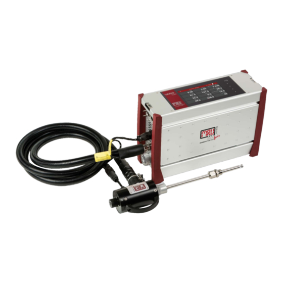
The analyser consists of a compact and robust metal housing with shock-absorbing rubber corners. All electrical and pneumatic connections are located on both front sides of the instrument. It is operated exclusively via the touch-sensitive touch screen. 12 / 118 MRU GmbH, D-74172 Neckarsulm... -
Page 13: Connectors
Hose connection DN 4/6 Sample gas outlet port Fresh air inlet port Sample gas inlet port Outlet fan of gas cooler Probe connection, electrical Pressure-/diff. pressure Pressure-/diff. pressure Combustion air temperature (Absolute pressure) AUX socket 13 / 118 MRU GmbH, D-74172 Neckarsulm... -
Page 14: Probes
• Probe adapter set HPI for existing probe tubes (see chapter 14.5) for connecting ON-SITE existing 6- or 8-mm tubes to the probe handle INSTEAD of the enclosed MRU probe tube. But then no measurement of the flue gas temperature is possible with... -
Page 15: Heated Gas Sampling Probe
► Roll out the heated hose line completely for each measure- ment. ATTENTION When measuring with coiled heated hose line, the hose line is destroyed due to strong heat development. ► Roll out the heated hose line completely for each measure- ment. 15 / 118 MRU GmbH, D-74172 Neckarsulm... -
Page 16: Unheated Gas Sampling Probe
Filter lock Fast locking coupling Cable coupler (5-pin) Cable plug (14-pin) Fast locking coupling Unheated hose line Probe cone Probe tube Probe handle ► Check the probe filter before and after every measurement. 16 / 118 MRU GmbH, D-74172 Neckarsulm... -
Page 17: Gas Conditioning
3. The analyser works with a non-dispersive infrared absorption for the Measurement of CO, CO and CH 4. H can be measured with a TCD/thermal conductivity detector. 5. Measuring module for the measurement of H 17 / 118 MRU GmbH, D-74172 Neckarsulm... -
Page 18: Operation
The remaining time until the end of zeroing is displayed. 4.2. Operating panel All functions are controlled via the touch surface of the instrument. Different gestures are available in the individual menus and windows. 18 / 118 MRU GmbH, D-74172 Neckarsulm... -
Page 19: Charging The Battery
► Carry out only data processing and setting work in bat- tery operation. 4.4. Switching on the analyser ► Touch the ⏻ button (1) for 3 sec. minimum LED lights blue ► Release the ⏻ button (1). Analyser runs up. 19 / 118 MRU GmbH, D-74172 Neckarsulm... -
Page 20: Switching Off The Analyser
The analyser shuts down. 4.6.Turn Display ► Touch the Context menu (19) on the display. A selection list appears. ► Touch Display settings. A window appears. Touch The display turns. 20 / 118 MRU GmbH, D-74172 Neckarsulm... -
Page 21: Set The Analyser To Standby Mode
► Press MEASUREMNT MODE? to restart the analyser. A message appears. ► Press Yes to exit the standby mode. A message appears. ► Press OK. The analyser is heated up. ► If necessary, perform a new zeroing. 21 / 118 MRU GmbH, D-74172 Neckarsulm... -
Page 22: Back To Homescreen / Back To Measure
► Touch the button 2 and button 3 simultaneously for 3 seconds. See also chapter 4.2 Operating panel, page 18. A folder “Screenshots is created on the USB-Stick. The screenshot is saved as PNG in the "Screenshots" folder. 22 / 118 MRU GmbH, D-74172 Neckarsulm... -
Page 23: Settings
► Open the menu Settings. See also chapter 5.1 Open menu Settings, S. 23. ► Press General settings. A window appears. In the menu General settings, you can make the following adjustments: 23 / 118 MRU GmbH, D-74172 Neckarsulm... -
Page 24: Setting Date And Time
5.3.Setting Date and Time ► Open the menu Settings. See also chapter 5.1 Open menu Settings, S. 23. ► Press General settings. A window appears. ► Press SET DATE TIME A window appears. 24 / 118 MRU GmbH, D-74172 Neckarsulm... -
Page 25: Device Settings
The analyser displays a corresponding message. ► Select a valid date. 5.4.Device settings ► Open the menu Settings. See also chapter 5.1 Open menu Settings, S. 23. ► Press Device settings. A window appears. 25 / 118 MRU GmbH, D-74172 Neckarsulm... - Page 26 Modbus address of the instrument for the remote control via Modbus Hold delay after purge Time in which Analog outputs main- tain their value after zero-point meas- urement Aux connector Analogue input for TC, 0-10 V, 4...20mA, RS485 26 / 118 MRU GmbH, D-74172 Neckarsulm...
-
Page 27: Water Monitoring
► Open the menu Settings. See also chapter 5.1 Open menu Settings, S. 23. ► Press Water monitoring. A window appears. ► Activate water monitoring 27 / 118 MRU GmbH, D-74172 Neckarsulm... - Page 28 0 reference [ppm] value is displayed. Monitoring status shows: Monitoring was initialized. Waiting time after zeroing After the set time from start monitoring after zeroing has elapsed, mon- itoring starts. Monitoring status shows: Monitoring is running 28 / 118 MRU GmbH, D-74172 Neckarsulm...
- Page 29 ► You have the possibility to ignore the message and reset the water moni- toring. The water monitoring starts again. ► You have the possibility to ignore the message and stop the water moni- toring. You can also set, that a zero point is taken automatically 29 / 118 MRU GmbH, D-74172 Neckarsulm...
-
Page 30: Averaging
The number of read values is counted up according to the set time in- terval. As soon as the set time interval is reached, the number of read values remains constant. 30 / 118 MRU GmbH, D-74172 Neckarsulm... - Page 31 As soon as the set time interval has been reached, the average value is constantly recalculated by replacing the last value read with the cur- rently read value. 31 / 118 MRU GmbH, D-74172 Neckarsulm...
-
Page 32: Interval Measurement
► Set the duration of the Standby time, the duration of the Measurement time and the amount of Measurement cycles. ► Press TAKE TIME OVER / SET AMOUNT. The set time/amount is taken over. The expected time is adjusted. 32 / 118 MRU GmbH, D-74172 Neckarsulm... - Page 33 A window appears. ► Set the desired interval. ► Set whether Mean values should be calculated. ► Press OK. The menu Please select site appears. The following icon appears in the display 33 / 118 MRU GmbH, D-74172 Neckarsulm...
- Page 34 Information on the remaining time of the measurement and the re- maining measurement cycles is displayed. After the set measurement time has been completed, a flushing pro- cess is initiated. 34 / 118 MRU GmbH, D-74172 Neckarsulm...
- Page 35 After the warm-up phase has elapsed, a zeroing is initiated. After taking the zero point, another measurement is started The process repeats itself according to the set amount of measurement cycles. 35 / 118 MRU GmbH, D-74172 Neckarsulm...
-
Page 36: Programs
► Enter the desired Program name. ► Exit the menu ► Press Selected measuring program. See also chapter 4.2 Operating panel, Page 18. The changed program name is shown in the display. 36 / 118 MRU GmbH, D-74172 Neckarsulm... -
Page 37: Analog Output Setup (4-20Ma)
► Press Analog output setup (4-20mA). A window appears. ► Choose the desired channel. A selection list appears. ► Choose the desired measurrand. ► Press “OK“. The measurand is assigned to the desired channel. 37 / 118 MRU GmbH, D-74172 Neckarsulm... -
Page 38: Setting Lower / Higher Limit
► Enter the desired values for the lower and higher limit. ► Press „OK“. ► Press "Default" to set the default values for the lower and upper limits. The lower and higher limit are assigned to the desired channel. 38 / 118 MRU GmbH, D-74172 Neckarsulm... -
Page 39: Setting Analog Outputs During Zeroing
► Press „Analog output setup (4-20mA)“. A window appears. ► Press„Analog output setup (4-20mA)“. A window appears. ► Scroll to graphic representation of the pin assignment of the 4-20 mA inter- face. 39 / 118 MRU GmbH, D-74172 Neckarsulm... -
Page 40: Analog Input Setup (4-20Ma)
A window appears. ► Choose the desired channel. A window appears. ► Enter the desired values. ► Go back. The values appear in the selection list. The incoming measurand is displayed. 40 / 118 MRU GmbH, D-74172 Neckarsulm... -
Page 41: Connecting Analyser With Wifi (Wlan)
A window appears. ► Switch on the WLAN. The available WLAN connections are displayed. NOTE Press the button REFRESH, if no WLAN connection is displayed ► Select the desired WLAN-Connection. A window appears. 41 / 118 MRU GmbH, D-74172 Neckarsulm... - Page 42 ► Alternatively, press the context menu button to display the WLAN IP. ► Use the displayed WLAN -IP for MRU4win (in this example 192.168.43.53). See also Chapter 15.4 Connecting analyser with MRU4win, Page 111. 42 / 118 MRU GmbH, D-74172 Neckarsulm...
-
Page 43: Getting Information About The Network
Information about the network appear. 5.13.Assigning a fixed IP address ► Open the menu Settings. See also chapter 5.1 Open menu Settings, S. 23. ► Press Network A window appears. 43 / 118 MRU GmbH, D-74172 Neckarsulm... -
Page 44: Serial Connectivity (Rs485/Usb)
The middle LED (Connect) should flash on both converters. The two converters are connected. ► Open the menu Settings. See also chapter 5.1 Open menu Settings, S. 23. ► Select Serial connectivity (RS485/USB) A window appears. 44 / 118 MRU GmbH, D-74172 Neckarsulm... - Page 45 MRU4Win. In this example the Comport is Com 3. You can find more information in the MS Windows Device Manager. • Baud rate = 19200 • Data Bits = 8 • Parity = Even • StopBits = One 45 / 118 MRU GmbH, D-74172 Neckarsulm...
-
Page 46: Default Settings
► Open the menu Settings. See also chapter 5.1 Open menu Settings, S. 23. ► Press Default settings A window appears. ► Press OK. The analyser is reset to factory default 46 / 118 MRU GmbH, D-74172 Neckarsulm... -
Page 47: Configuration Of Measurement Program
The other value fields move automatically. Assign a measured value ► Touch the menu Measure The measurement window appears. ► Double touch the value field. A selection list appears. ► Touch the desired measurand. 47 / 118 MRU GmbH, D-74172 Neckarsulm... -
Page 48: Setting Zoom
► Touch „replace “or „insert “. Setting zoom ► Touch the menu Measure. The measurement window appears. ► Swipe left on the Touchscreen. The measured values are displayed in the zoom display. 48 / 118 MRU GmbH, D-74172 Neckarsulm... -
Page 49: Measurement
► You can operate a 230V heating hose with 110 volts, but with limited heat capacity. DANGER Risk due to improper use Risk of death due to electric shock ► Do not operate a 110V heating hose with 230V. 49 / 118 MRU GmbH, D-74172 Neckarsulm... -
Page 50: Operating Temperature
In this case, check the ambient air. If the Setting “Analyser start with – stored zero point “is activated the ambient air is not checked See also Chapter 5.4 Device settings, Page 25. 50 / 118 MRU GmbH, D-74172 Neckarsulm... -
Page 51: Repeated Zero Point
2 pm. The next automatic zero- ing would be at 6 pm. At 4 pm you carry out a manually ini- tiated zeroing. The time grid is shifted. The next automatic zeroing takes place at 8 pm. 51 / 118 MRU GmbH, D-74172 Neckarsulm... -
Page 52: Use Last Valid Zero Point
No new zero point is taken after switching on. The zero-point bar is orange in this case. NOTE Please note that for the O2 sensor, regardless of this set- ting, a zero-point measurement is performed after each switch-on. 52 / 118 MRU GmbH, D-74172 Neckarsulm... -
Page 53: Select Source Zero Point (Gas)
► Choose the desired option. The zero gas is sucked in either via the probe or the fresh air inlet. NOTE After switching on, the first zero point is always taken via the fresh air inlet. 53 / 118 MRU GmbH, D-74172 Neckarsulm... -
Page 54: Charging State Of The Battery
Check also whether there is a device alarm. Temperatures of NDIR and heating hose should be within the specified range in order to guarantee a sufficient measuring accuracy. See Chapter 13 Specifications, S. 96. 54 / 118 MRU GmbH, D-74172 Neckarsulm... -
Page 55: Attach Clip-On Filter
If you operate the analyser without a heated hose, dirt may collect in the gas inlet. ► In this case, plug the supplied clip-on filter onto the gas inlet (12). Controlling Filters The filters (probe filter and round filter) must be checked before and after each measurement. 55 / 118 MRU GmbH, D-74172 Neckarsulm... -
Page 56: Take A Measurement
► Touch the menu „Measure “. The measurement window appears. ► Touch the context menu (19). A selection list appears. ► Touch „CO purge limit“. A window appears ► Set the desired CO threshold value. 56 / 118 MRU GmbH, D-74172 Neckarsulm... -
Page 57: Starting The Measurement
A selection list appears. ► Choose the desired site. The measured values are stored. The measurement continues until you switch off the analyser. See also Chapter Recalling stored measurements, Page 66. 57 / 118 MRU GmbH, D-74172 Neckarsulm... -
Page 58: Select Channels For Graphic Display
The window with "Recorded channels" appears. ► Press a measurand that you want to replace. A window appears. ► Select the desired measurand. ► Press OK. The measurand is replaced. 58 / 118 MRU GmbH, D-74172 Neckarsulm... - Page 59 ► Press the graphic symbol. A diagram appears. ► If necessary, touch to stop the graphical display. The measurement will be continued in the background. ► If necessary, touch to continue the graphical display. 59 / 118 MRU GmbH, D-74172 Neckarsulm...
-
Page 60: Starting Auto-Measurement
► Touch „OK “ The window „Please select site “appears. ► Select the desired site. The Auto-measurement starts automatically. The Auto-measurement ends automatically. A protocol of the Auto-measurement appears 60 / 118 MRU GmbH, D-74172 Neckarsulm... - Page 61 You can also export or print the data of the automatic measurement. ► Insert a USB-stick into the analyser. ► Touch the context menu. A Selection list appears. ► Select Export CSV or Print. The data is exported or printed 61 / 118 MRU GmbH, D-74172 Neckarsulm...
-
Page 62: Stopping Auto-Measurement
The Auto-measurement can be stopped manually at any time. ► Touch the context menu (19) while the measurement is recorded. A selection list appears. ► Touch „Stop logging “ The Auto-measurement is stopped. 62 / 118 MRU GmbH, D-74172 Neckarsulm... -
Page 63: Data Memory
Adding a new site ► Press the menu Sites. An window appears. ► Press ADD SITE. A window appears. ► Enter the site data. ► Touch „SAVE “. The site is saved. 63 / 118 MRU GmbH, D-74172 Neckarsulm... -
Page 64: Changing Site Data
► Touch the menu Sites. A selection list appears. ► Select the desired site. A window appears. ► Change the desired data. ► Touch „STORE “. The changes are stored. 64 / 118 MRU GmbH, D-74172 Neckarsulm... -
Page 65: Deleting Sites
User Manual VARIOluxx Syngas Deleting sites ► Press the menu Sites. A selection list appears. ► Select the desired site. A window appears. ► Press Delete. The site is deleted. 65 / 118 MRU GmbH, D-74172 Neckarsulm... -
Page 66: Recalling Stored Measurements
• You can delete measurements individually. • You can select several measurements and delete them at the simulta- neously. ► Press the menu sites. A selection list appears. ► Press the desired site. A window appears. 66 / 118 MRU GmbH, D-74172 Neckarsulm... - Page 67 User Manual VARIOluxx Syngas ► Press MEASUREMENTS. The stored measurements are displayed. Delete single measurements ► Press A message appears. ► Press YES The selected measurement is deleted. 67 / 118 MRU GmbH, D-74172 Neckarsulm...
-
Page 68: Data Transfer Via Usb (Csv Export)
CSV is a simple file format that is widely supported, so it is of- ten used to move tabular data between different computer programs, for ex- ample Microsoft Excel™ or Access™, that support the format. The following functions are available 68 / 118 MRU GmbH, D-74172 Neckarsulm... - Page 69 You have the option of exporting several measurements in one file. ► Select the desired measurement. The button EXPORT CHECKED AS CSV becomes active The button EXPORT CHECKED IN ONE FILE becomes active. 69 / 118 MRU GmbH, D-74172 Neckarsulm...
- Page 70 The directory 1113Export is created on the USB stick. The selected measurements are stored in the 1113Export directory. ► Open the CSV file. (Do not use dat-files or internal log files) Export with header Export without header 70 / 118 MRU GmbH, D-74172 Neckarsulm...
-
Page 71: Extras
► Open the menu Extras. See also chapter 8.1 Open menu Extras, S. 71 A selection list appears. ► Press „History“. A window appears. ► Press „DATE“. A selection list appears. 71 / 118 MRU GmbH, D-74172 Neckarsulm... - Page 72 You have the possibility to change the displayed channels and to have them displayed graphically. You have the possibility to change the Starttime and the Endtime. You can activate or deactivate the selected time axis. ► If necessary, press A window appears 72 / 118 MRU GmbH, D-74172 Neckarsulm...
-
Page 73: System Extensions
The options stored on the USB stick are displayed. ► Press UPDATE LIST, if no options are displayed. ► Select the desired Options. ► Press LOAD CHECKED OPTIONS. A message appears. 73 / 118 MRU GmbH, D-74172 Neckarsulm... -
Page 74: Connections
► Open the menu Extras See also chapter 8.1 Open menu Extras, Page 71. ► Press Automatic device start A window appears. ► Set the desired time for the automatic device start. 74 / 118 MRU GmbH, D-74172 Neckarsulm... -
Page 75: Instrument Leak Test
See also chapter 8.1 Open menu Extras, Page 71. ► Press Instrument leak test. A window appears. If the analyser is still in the warm-up phase, no leak test can be per- formed. A corresponding message is displayed. 75 / 118 MRU GmbH, D-74172 Neckarsulm... - Page 76 If the system is tight, the traffic light is green and the l/h pointer is 0. ► Exit the window. NOTE Note that measured values are invalid for four minutes af- ter the Instrument leak test. If you open the menu Measure, a corresponding message will be displayed 76 / 118 MRU GmbH, D-74172 Neckarsulm...
-
Page 77: Printing Measurement Results
► Go to the menu Measurement. The measurement window appears. ► Press the “Context menu” (19). A selection list appears. ► Press Print. The measurement is printed out with a slight delay. 77 / 118 MRU GmbH, D-74172 Neckarsulm... -
Page 78: Printing Stored Measurement Results
► Press the desired site. A window appears. ► Press MEASUREMENTS. The stored measurements are displayed. ► Press the desired measurement. The measurement window appears. ► Press the context menu (19). 78 / 118 MRU GmbH, D-74172 Neckarsulm... - Page 79 User Manual VARIOluxx Syngas A selection list appears. ► Press „Print“. The measurement is printed out with a slight delay 79 / 118 MRU GmbH, D-74172 Neckarsulm...
-
Page 80: Service
► Open the menu Service. See also chapter 9.1 Open menu Service, Page 80. ► Press Service values. Internal parameters and their values appear. 80 / 118 MRU GmbH, D-74172 Neckarsulm... -
Page 81: Performing Device Selftest
As long as the Device selftest is running, appears in the display. The Device selftest stops automatically. A successful Device selftest is indicated with in the display for each individual parameter. 81 / 118 MRU GmbH, D-74172 Neckarsulm... -
Page 82: Internal Log Settings
In the case of an Error message, please contact our customer service or contact one of the worldwide MRU service partners via www.mru.eu 9.4.Internal log settings The analyser stores internal parameters at regular intervals to allow for an op- timized support from experienced service staff. -
Page 83: Copying Single Log Data
► Open the menu Service. See also chapter 9.1 Open menu Service, Page 80. ► Press Internal log settings. A window appears. ► Press FILE BROWSER A selection list appears. 83 / 118 MRU GmbH, D-74172 Neckarsulm... - Page 84 The directory [serial number] Logg was created on the USB-Stick. The log files are saved in the directory [serial number]. After copying, the display shows "File(s) successfully copied". ► Press „OK 84 / 118 MRU GmbH, D-74172 Neckarsulm...
-
Page 85: Export Ndir - Factors
The NDIR factors are exported. On the USB stick, the folder NdirFactors is created. The NDIR factors are stored in the folder NdirFactors. A message appears. ► Press OK. 85 / 118 MRU GmbH, D-74172 Neckarsulm... -
Page 86: Info
► Open the menu Info. See also chapter 10.1 Open menu Info, S.86. ► Press Device info. A window appears. ► Press INFO A window appears. Version information for specific modules is displayed 86 / 118 MRU GmbH, D-74172 Neckarsulm... - Page 87 User Manual VARIOluxx Syngas ► Exit the window. ► Press OPTIONS. A window appears. The installed options are displayed. 87 / 118 MRU GmbH, D-74172 Neckarsulm...
-
Page 88: Device Usage
See also chapter 10.1 Open menu Info, S.86. ► Press Device usage. A window appears. If a device component has exceeded the prescribed service life, the analyser should be maintained immediately at a service centre. 88 / 118 MRU GmbH, D-74172 Neckarsulm... -
Page 89: Maintenance And Cleaning
► Check the round filter at the front of the instrument. Replace the filter if necessary. 11.2. Service check An annual service check and if necessary, adjustment of the sensors at an MRU service department (www.mru.eu) are recommended for the preservation of value . -
Page 90: Simple Service Work
If necessary, you will receive a new released data package from the manufac- turer for updating the firmware and the individual modules. The data package consists of a ZIP data package. The data package has the ending .mru. Update main firmware ►... - Page 91 ► Press Software update. A window appears. NOTE Please note that you must first update the main firmware. After the restart you can update the modules. ► Press LOAD FROM STICK. A message appears. 91 / 118 MRU GmbH, D-74172 Neckarsulm...
- Page 92 If no data package is displayed, save the received data package again on a USB stick. If the data package is not displayed again, contact cus- tomer service or one of the MRU service partners world- wide. ► Select the desired data package.
- Page 93 A message appears. To conclude the update process, the analyser must be restarted. ► Press YES. The analyser performs a restart. You can now update the software of single modules. 93 / 118 MRU GmbH, D-74172 Neckarsulm...
-
Page 94: Update Firmware Of Single Modules
► Press SINGLE MODULE UPDATE. A window appears. ► Select the desired module that you want to update. A message appears. ► Press YES. The update is started. 94 / 118 MRU GmbH, D-74172 Neckarsulm... - Page 95 User Manual VARIOluxx Syngas After the update has been performed successfully, a message appears. ► Press OK. ► Please restart the system. 95 / 118 MRU GmbH, D-74172 Neckarsulm...
-
Page 96: Specifications
Maße ohne Koffer (BxHxT) Size unit w/ocase (WxHxD) 15cm 52cm x 51cm x30 Maße inkl. Koffer (BxHxT) Size incl. Case (WxHxD) Gehäusematerial Aluminium / TPU Housing Material Schutzart IP20 IP degree of protection 96 / 118 MRU GmbH, D-74172 Neckarsulm... -
Page 97: Gas Sampling And Conditioning
Messbereich 0..25 Vol% Measuring Range Auflösung 0,01 Vol% Resolution 0..25 Vol.% ± 0,1 Vol.% Genauigkeit Accuracy 25 .. 100 Vol.% ± 0,2 Vol.% WLD Wärmeleitfähigkeitsde- TCD (thermal conducti- H2 #11092 tektor vity detector) 97 / 118 MRU GmbH, D-74172 Neckarsulm... -
Page 98: Specifications Of Ndir Technology
Accuracy 13.4. Specifications of NDIR technology Art.Nr. Range Resolution Accuracy 10774 100% 0,01% ±0,3% Vol% / 2% 100% 0,01% ±0,3% Vol% / 2% 40 s 100% 0,01% ±0,3% Vol% / 2% 40 s 98 / 118 MRU GmbH, D-74172 Neckarsulm... -
Page 99: Calculated Values And Accessories
RS485 (isoliert, für Anbindung an RS485 (isoliated, for connec- Ο tion to PC)) Analog I/O: 4x input, 8x output, Analog I/O: 4x input, 8x out- Ο 4... 20 mA put, 4... 20 mA 99 / 118 MRU GmbH, D-74172 Neckarsulm... -
Page 100: Fuel Type List
User Manual VARIOluxx Syngas 13.7. Fuel type list This list is for Germany only. Fuel types from other countries can be obtained from MRU GmbH: Web page: www.mru.eu Germany O2max 20,96 Fuel CO2max Test gas 0,00 0,00 0,000 Natural gas (LL) -
Page 101: Options
Pitot tube with thermocouple. Position Description Connection total pressure Connection static pressure Thermocouple Connection T-AIR Connection AUX NOTE Note that you can use either the connection T-AIR or the connection AUX. 101 / 118 MRU GmbH, D-74172 Neckarsulm... -
Page 102: Parameter For Gas Flow Measurement
• Via the connection T-AIR (T-air) • Via the connection AUX (AUX-tc) See also chapter Connect analyser to Pitot tube, S. 101. ► Change the desired parameters. ► Press CHOOSE UNITS. A setting window appears. 102 / 118 MRU GmbH, D-74172 Neckarsulm... -
Page 103: Operating Analyser With Nickel-Metal-Hybrid (Nihm)-Battery
► The analyser displays a message if no power supply is connected. The message appears 45 seconds after switching on. The message appears after 90 seconds if the power supply unit is re- moved during operation. 103 / 118 MRU GmbH, D-74172 Neckarsulm... -
Page 104: Rs485 Extern (Option)
4 = Connector to RS485 port (option) 5 = Not used NOTE: one twisted pair of shielded cable is user scope Port settings: Baud Rate: 19200 Data bits: 8 Parity: Even Stop bits: 1 Slave ID: 1 104 / 118 MRU GmbH, D-74172 Neckarsulm... -
Page 105: Screw Adapter Onto Hpi-Probe (Option)
When screwing the adapter onto the HPI probe, pay attention to the size of your probe tube. ► Screw the adapter onto the HPI probe. ► Screw your probe tube onto the adapter. 105 / 118 MRU GmbH, D-74172 Neckarsulm... -
Page 106: Appendix
15.1. Error diagnosis regarding the measuring instrument Fault indication Possible causes Repair Gas cooler is faulty! Gas cooler faulty. Contact MRU service department. The system will shut down. Undervoltage!!! Battery is discharged. Connect instrument to power grid. The System will shut... -
Page 107: Condensate Alarm
As soon as the "Condensate self-help" has been successfully completed, a message appears. A zero point measurement is started automatically. You can display the start and end of the "Condensate self-test 107 / 118 MRU GmbH, D-74172 Neckarsulm... -
Page 108: Start Drying Manually
► Dispose of acidic condensate and phosphoric acid in ac- cordance with national and, if necessary, local disposal guidelines. ► Remove the round filter. ► Dry the round filter, if necessary. ► Press OK. A window appears 108 / 118 MRU GmbH, D-74172 Neckarsulm... -
Page 109: Switching Off The Analyser In Case Error
485). See also Chapter 14.3 RS485 Extern (Option), S.104. ► You can connect Modbus devices to MRU4win via a TCP/IP connection. The TCP/IP connection can be made by LAN or WLAN. 109 / 118 MRU GmbH, D-74172 Neckarsulm... -
Page 110: Connecting Analyser With Mru4Win Via Serial Interface (Rs 485)
A selection list appears. ► Press “Display settings”. An overview screen appears. In the top line, the IP address of the analyser is displayed. In this example the LAN address is 192.168.44.38. 110 / 118 MRU GmbH, D-74172 Neckarsulm... -
Page 111: Creating Analyser In Mru4Win
Before you can connect the analyser with MRU4win, you have to create a Modbus device. ► Open MRU4win. ► Set under "General” a check mark at "Activate Modbus". ► Click “Create Modbus Device”. 111 / 118 MRU GmbH, D-74172 Neckarsulm... - Page 112 ► If necessary, enter your IP address, if you want to set up a TCP/IP connec- tion. In this example the LAN address is 192.168.44.38. See Example in Chapter Connecting analyser with MRU4win via TCP/IP connection, Page 110. 112 / 118 MRU GmbH, D-74172 Neckarsulm...
- Page 113 User Manual VARIOluxx Syngas ► Click “OK”. ► Go to “Livemeasurements”. The analyser appears in the column of available analysers. ► Click on the "Connect-Icon” The analyser is connected. 113 / 118 MRU GmbH, D-74172 Neckarsulm...
-
Page 114: Remote Control Of The Analyser Via Vnc
► Use remote control via Android device. NOTE Please note that due to the increased computing power, the CPU temperature will increase. If the temperature should become too high, the VNC server switches off auto- matically. 114 / 118 MRU GmbH, D-74172 Neckarsulm... -
Page 115: General Instructions For The Heated Hose Line
Right Wrong Don`t tear the heated sam- Roll the heated hose line pling line out. -> smooth out. Cause sharp kink. 115 / 118 MRU GmbH, D-74172 Neckarsulm... -
Page 116: Bending Radius Of Heated Sampling Lines
Probe filter sintered metal 2 μm 61157 Probe filter sintered metal 20 μm 10825 Mineral wool filter element 59799 O-Ring 16 x 1,5 61066 O-Ring 12 x 2 61333 O-Ring 10 x 2 60074 O-Ring 8 x 2 116 / 118 MRU GmbH, D-74172 Neckarsulm... -
Page 117: Declaration Of Conformity
User Manual VARIOluxx Syngas 16 Declaration of conformity 117 / 118 MRU GmbH, D-74172 Neckarsulm...
Need help?
Do you have a question about the SYNGAS VARIOluxx and is the answer not in the manual?
Questions and answers