Emerson Rosemount 5408 Reference Manual
Level transmitters
Hide thumbs
Also See for Rosemount 5408:
- Reference manual (274 pages) ,
- All-in-one quick start manual (44 pages) ,
- Quick start manual (37 pages)

Related Manuals for Emerson Rosemount 5408


Summary of Contents for Emerson Rosemount 5408
- Page 1 Reference Manual 00809-0100-4408, Rev CE March 2023 Rosemount ™ 5408 and 5408:SIS Level Transmitters Non-Contacting Radar with HART Protocol ®...
- Page 2 Ensure the transmitter is installed by qualified personnel and in accordance with applicable code of practice. Use the equipment only as specified in this manual. Failure to do so may impair the protection provided by the equipment. For installations in hazardous locations, the transmitter must be installed according to the Rosemount 5408 Product Certifications document and System Control Drawing.
- Page 3 Emerson. Any continued use of product that has been damaged or modified without the written authorization is at the customer’s sole risk and expense.
-
Page 5: Table Of Contents
79 5.7 Configure transmitter using guided setup................79 5.8 Run verify level...........................80 5.9 Multidrop communication....................... 80 ® ™ 5.10 Use with the Rosemount 333 HART Tri-Loop ..............80 5.11 Write protect a transmitter....................81 Chapter 6 Operation..........................83 Rosemount 5408 and 5408:SIS Level Transmitters... - Page 6 Contents Reference Manual March 2023 00809-0100-4408 6.1 LCD display screen messages....................83 6.2 Select the display variables...................... 84 6.3 View measurement data......................85 6.4 Check device status........................85 6.5 Smart echo level test.........................88 Chapter 7 Service and troubleshooting....................91 7.1 Safety messages........................91 7.2 Diagnostic messages per NAMUR NE 107................92 7.3 Troubleshooting guides......................
-
Page 7: Chapter 1 Introduction
Specifications and reference data supplies reference and specification data, as well as ordering information for spare parts and accessories. Configuration parameters provides extended information about the configuration parameters. Rosemount 5408 and 5408:SIS Level Transmitters... -
Page 8: Namur Ne 53 Revision History
March 2023 00809-0100-4408 1.2 NAMUR NE 53 revision history The Rosemount 5408 meets the NAMUR recommendation NE 53. Table 1-1 provides the information necessary to ensure you have the correct device driver for your device. Table 1-1: Identification and Compatibility According to NAMUR NE 53... -
Page 9: Chapter 2 Transmitter Overview
Transmitter overview 2.1 Measurement principle The Rosemount 5408 is a two-wire transmitter for continuous level measurements using fast-sweep Frequency Modulated Continuous Wave (FMCW) technology. The transmitter continuously emits signal sweeps with a constantly varying frequency towards the product surface. Since the transmitter continuously changes the frequency of... - Page 10 Transmitter overview Reference Manual March 2023 00809-0100-4408 transmitter may be mounted in a still pipe. In addition, measurement performance can be optimized by configuring the appropriate process conditions settings. Measurement in foamy applications depends largely on the foam properties. When the foam is light and airy, the actual product level is measured.
-
Page 11: Vessel Characteristics
2.4 Application examples The Rosemount 5408 and 5408:SIS are ideal for level measurements over a broad range of liquid and solids applications. The transmitters are virtually unaffected by changing density, temperature, pressure, media dielectric, pH, and viscosity. Non-contacting radar level is ideal for harsh conditions such as corrosive and sticky media, or when internal tank obstructions are a limiting factor. - Page 12 Blenders and mixers The Rosemount 5408 can help you withstand the rigors of blenders and mixing tanks. Easy to install and commission, it is also unaffected by virtually any fluid property change. Open atmospheric applications The Rosemount 5408 measures reliably in open applications, from short range sumps or ponds to long range dams.
-
Page 13: Components Of The Transmitter
March 2023 Still pipe and chamber installations The Rosemount 5408 is a great choice for level measurement in tanks with small diameter still pipes. It may also be used in chambers, but guided wave radar is generally the best fit for these applications. -
Page 14: System Integration
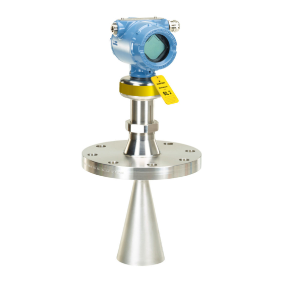
Transmitter overview Reference Manual March 2023 00809-0100-4408 Figure 2-2: Components A. Terminal compartment B. Transmitter housing (aluminum or stainless steel) C. Sensor module with signal processing electronics D. External ground screw E. Flanged process connection F. Cone antenna G. Two cable/conduit entries (½-14 NPT, M20 x 1.5, or G½); Optional adapters: eurofast ™... - Page 15 E. Approved IS barrier (for Intrinsically Safe installations only) F. Rosemount 333 G. Host/DCS system H. HART modem I. PC with Rosemount Radar Master Plus The Rosemount 5408 is compliant with NAMUR NE 107 Field Diagnostics for standardized device diagnostic information. Rosemount 5408 and 5408:SIS Level Transmitters...
- Page 16 Transmitter overview Reference Manual March 2023 00809-0100-4408 Reference Manual...
-
Page 17: Chapter 3 Mechanical Installation
Ensure that the transmitter is handled carefully. If the process seal is damaged, gas might escape from the tank. WARNING Explosions could result in death or serious injury. Verify that the operating atmosphere of the transmitter is consistent with the appropriate hazardous locations certifications. Rosemount 5408 and 5408:SIS Level Transmitters... -
Page 18: Confirm Approval Type
Do not install the transmitter in the center of the tank. • Do not mount close to or above the inlet stream. • Multiple Rosemount 5408 transmitters can be used in the same tank without interfering with each other. Reference Manual... - Page 19 3-2). Figure 3-3: Free Space Requirements Table 3-1: Distance to Tank Wall (L) Application Minimum Recommended Liquids 8 in. (200 mm) ½ of tank radius Solids 8 in. (200 mm) ⅔ of tank radius Rosemount 5408 and 5408:SIS Level Transmitters...
- Page 20 Mechanical installation Reference Manual March 2023 00809-0100-4408 Table 3-2: Free Space Requirements Description Distance Service space width (A) 20 in. (500 mm) Service space height (B) 24 in. (600 mm) 3.3.3 Antenna size Choose as large antenna diameter as possible. A larger antenna diameter concentrates the radar beam and ensures maximum antenna gain.
- Page 21 Figure 3-5: Beam Angle and Beam Width Table 3-3: Beam Angle Antenna size Beam angle (α) 1½-in. (DN 40) cone 22° 2-in. (DN50) cone/process seal 18° 3-in. (DN80) cone/process seal 14° 4-in. (DN100) cone/process seal 10° 8-in. (DN200) parabolic 4.5° Rosemount 5408 and 5408:SIS Level Transmitters...
- Page 22 Mechanical installation Reference Manual March 2023 00809-0100-4408 Table 3-4: Beam Width, ft. (m) Distance Beam width (W) 1½-in. cone 2-in. cone/ 3-in. cone/ 4-in. cone/ Parabolic process seal process seal process seal 16 (5) 6.2 (1.9) 5.2 (1.6) 4.0 (1.2) 2.9 (0.9) 1.3 (0.4) 33 (10) 12.8 (3.9)
- Page 23 For hygienic applications, the nozzle height (H) must not exceed two times the nozzle diameter (D) to ensure cleanability. Maximum nozzle height is 5 in. (127 mm). Nozzle requirements for parabolic antenna Table 3-7 for nozzle height recommendations at different inclination angle. Rosemount 5408 and 5408:SIS Level Transmitters...
- Page 24 Mechanical installation Reference Manual March 2023 00809-0100-4408 Figure 3-8: Mounting of the Parabolic Antenna Ø 8 in. (200 mm) A. Nozzle mounting B. Flange mounting in manhole cover Table 3-7: Nozzle Requirements for Parabolic Antenna, in Inches (Millimeters) Nozzle size (D) Inclination angle (α) Maximum nozzle height (H) Pipe schedule std, Ø...
- Page 25 C. Minimum 6 in. (150 mm) D. Maximum 1° E. Level = 100% F. Level = 0% A larger gap is inevitable for the 4-in. cone antenna in pipes with a diameter larger than 4 in. Rosemount 5408 and 5408:SIS Level Transmitters...
- Page 26 Mechanical installation Reference Manual March 2023 00809-0100-4408 Chamber Consider the following chamber requirements: • Pipes should be an all-metal material. • Pipe should have a constant inside diameter. • Inlet pipes should not protrude into the inside of the stand pipe. •...
-
Page 27: Mounting Preparations
47.2 in. (1200 mm). Procedure 1. Determine the antenna length. Figure 3-11: Installation Recommendation A. Min. 0.4 in. (10 mm) 2. Insert the segment into the cone antenna until it bottoms. Rosemount 5408 and 5408:SIS Level Transmitters... - Page 28 Mechanical installation Reference Manual March 2023 00809-0100-4408 3. Mark where to cut the segment. 4. Remove and cut the segment at the marking. 5. Remove any burrs. 6. Insert the segment into the cone antenna until it bottoms. 7. Secure the segment to the antenna. Note Be careful of sharp edges.
- Page 29 3. Cut the antenna at the marking. 4. Remove any burrs. 5. Measure the Antenna Extension Length (L). 6. Update the transmitter configuration to the new Antenna Extension Length (L). Select Configure → (Manual Setup) → Level Setup → Antenna. Rosemount 5408 and 5408:SIS Level Transmitters...
- Page 30 Mechanical installation Reference Manual March 2023 00809-0100-4408 3.4.3 Replace the transmitter head nut When mounting on a legacy Rosemount 5402 antenna, the transmitter head nut must be changed from size M50 to M52. Prerequisites Applies only to transmitters ordered with the option code A1. Procedure 1.
-
Page 31: Mount The Cone Antenna
A. Flanged version (see page B. Flanged version with air purge ring (see page C. Threaded version, D < d (see page D. Threaded version, D > d (see page E. Bracket mounting (see page Rosemount 5408 and 5408:SIS Level Transmitters... - Page 32 Mechanical installation Reference Manual March 2023 00809-0100-4408 3.5.2 Protective cap For spare antennas, keep the protective cap in place until installing the transmitter head. The cap protects the process seal from dust and water. Figure 3-14: Protective Cap 3.5.3 Flanged version Prerequisites If applicable, assemble the segmented cone antenna.
- Page 33 2. Place the purge ring over the gasket. 3. Place a suitable gasket over the purge ring. Note A minimum gasket thickness of 0.125 in. (3.2 mm) is required for flanges with protective plate design. Rosemount 5408 and 5408:SIS Level Transmitters...
- Page 34 Mechanical installation Reference Manual March 2023 00809-0100-4408 4. Lower transmitter with antenna and flange into the nozzle. A. Antenna with air purge holes 5. Tighten bolts and nuts with sufficient torque for the flange and gasket choice. A. 1.0 in. (25.5 mm) 6.
- Page 35 Gasket may be used as a sealant for adapters with 1½- or 2-in. BSPP (G) threads. 2. Mount the transmitter on the tank. A. Gasket (for 1½-in. and 2-in. BSPP (G) threads only) Postrequisites Align the transmitter head. Related information Assemble the segmented cone antenna Align transmitter head Rosemount 5408 and 5408:SIS Level Transmitters...
- Page 36 Mechanical installation Reference Manual March 2023 00809-0100-4408 Flanged tank connection Prerequisites If applicable, assemble the segmented cone antenna. Procedure 1. Place a suitable gasket on the tank flange. 2. Place the customer supplied flange over the gasket. 3. Tighten the bolts and nuts with sufficient torque for the flange and gasket choice. 4.
- Page 37 Prerequisites If applicable, assemble the segmented cone antenna. Procedure 1. Unscrew and remove the antenna. H2 mm Note Be careful not to scratch the microwave launcher. The microwave launcher is sensitive to mechanical impacts. Rosemount 5408 and 5408:SIS Level Transmitters...
- Page 38 Mechanical installation Reference Manual March 2023 00809-0100-4408 2. Apply anti-seize paste or PTFE tape on threads according to your site procedures. Gasket may be used as a sealant for adapters with 1½- or 2-in. BSPP (G) threads. 3. Mount the adapter on the customer supplied flange. A.
- Page 39 7. Tighten the bolts and nuts with sufficient torque for the flange and gasket choice. 8. Screw the adapter until it is properly tightened. Postrequisites Align the transmitter head. Related information Assemble the segmented cone antenna Align transmitter head Rosemount 5408 and 5408:SIS Level Transmitters...
- Page 40 Mechanical installation Reference Manual March 2023 00809-0100-4408 3.5.7 Mount the bracket Procedure 1. Mount the bracket to the pipe/wall. On pipe: A. Horizontal pipe B. Vertical pipe On wall: 2. Mount the holder to the bracket. Reference Manual...
- Page 41 Be careful not to scratch the microwave launcher. The microwave launcher is sensitive to mechanical impacts. 4. Screw the transmitter into the holder. 5. Mount the antenna. Torque 5 in-lb (0.5 N-m) H2 mm 38 mm Rosemount 5408 and 5408:SIS Level Transmitters...
- Page 42 Mechanical installation Reference Manual March 2023 00809-0100-4408 3.5.8 Align transmitter head Procedure 1. Loosen the nut slightly and turn the transmitter. 60 mm 2. Verify the transmitter head is properly aligned. Option Description Open tank Align the marking on the sensor module toward the tank wall (see Figure 3-15).
-
Page 43: Mount The Process Seal Antenna
Torque 355 in-lb (40 N-m) 60 mm 3.6 Mount the process seal antenna 3.6.1 Overview Figure 3-18: Overview A. Flanged version (see page B. Tri Clamp version (see page C. Bracket mounting (see page Rosemount 5408 and 5408:SIS Level Transmitters... - Page 44 Mechanical installation Reference Manual March 2023 00809-0100-4408 3.6.2 Mount the flanged version Procedure 1. Lower the transmitter into the nozzle. Note Be careful not to scratch or otherwise damage the PTFE sealing. Note Do not remove the PTFE sealing. 2. Tighten the bolts and nuts (see Table 3-8).
- Page 45 37 (50) 37 (50) 74 (100) 26 (35) 3.6.3 Mount the Tri Clamp version Procedure 1. Lower the transmitter into the nozzle. Note Be careful not to scratch or otherwise damage the PTFE sealing. Rosemount 5408 and 5408:SIS Level Transmitters...
- Page 46 Mechanical installation Reference Manual March 2023 00809-0100-4408 2. Tighten the clamp to the recommended torque (see the manufacturer’s instruction manual). Postrequisites Align the transmitter head. Related information Align transmitter head 3.6.4 Mount the bracket Procedure 1. Mount the bracket to the pipe/wall. On pipe: A.
-
Page 47: Mount The Parabolic Antenna
2. Mount the transmitter to the bracket. H5 mm 3.7 Mount the parabolic antenna 3.7.1 Overview Figure 3-19: Overview A. Flanged version (see page B. Threaded version (see page C. Welded version (see page D. Bracket mounting (see page Rosemount 5408 and 5408:SIS Level Transmitters... - Page 48 Mechanical installation Reference Manual March 2023 00809-0100-4408 3.7.2 Components of the parabolic antenna Components of the threaded version Figure 3-20: Components A. Antenna B. Purge plug kit C. Threaded sleeve D. M20 adapter E. Lock nut BSPP (G) 3½-in. F. Antenna adapter with ball joint G.
- Page 49 F. Flange ball G. O-ring H. Clamp flange I. Washer J. M8 screw K. Weld protection bar L. Ball joint 3.7.3 Mount the flanged version Procedure 1. Place a suitable gasket on the tank flange. Rosemount 5408 and 5408:SIS Level Transmitters...
- Page 50 Mechanical installation Reference Manual March 2023 00809-0100-4408 2. Lower the flange and antenna assembly into the nozzle. 3. Tighten the bolts and nuts with sufficient torque for the flange and gasket choice. Postrequisites 1. Adjust the inclination of the antenna. 2. Connect the air purging system. Related information Adjust the inclination of the antenna Connect the air purging...
- Page 51 A. Ø 3.98 ± 0.02 in. (Ø 101 ± 0.6 mm) or G 3½-in. B. Max. 0.59 in. (15 mm) 4. Remove the M20 adapter and visually inspect the O-rings for damage and dirt. 5. Carefully insert the antenna. Rosemount 5408 and 5408:SIS Level Transmitters...
- Page 52 Mechanical installation Reference Manual March 2023 00809-0100-4408 6. Secure the antenna. Torque 180 in-lb (20 N-m) 27 mm 7. Tighten the set screw. Torque 5 in-lb (0.5 N-m) H2 mm 8. Place a suitable gasket on the tank flange. 9. Lower the antenna assembly into the tank. Reference Manual...
- Page 53 10. Tighten the bolts and nuts with sufficient torque for the flange and gasket choice. Postrequisites 1. Adjust the inclination of the antenna. 2. Connect the air purging system. Related information Adjust the inclination of the antenna Connect the air purging Rosemount 5408 and 5408:SIS Level Transmitters...
- Page 54 Mechanical installation Reference Manual March 2023 00809-0100-4408 3.7.5 Mount the welded version Procedure 1. Mount the protection plates to flange/manhole cover. These plates protect the internal surfaces of the flange ball from dust and sparks during welding. A. Ø 3.94 ± 0.02 in. (Ø 100 ± 0.5 mm) B.
- Page 55 5. Mount the ball joint. a) Insert the ball joint and place the clamp flange with the “7 Nm” marking side b) Gradually tighten the M8 screws. Torque 65 in-lb (7 N-m) H6 mm Rosemount 5408 and 5408:SIS Level Transmitters...
- Page 56 Mechanical installation Reference Manual March 2023 00809-0100-4408 6. Remove the M20 adapter and visually inspect the O-rings for damage and dirt. 7. Carefully insert the antenna. 8. Secure the antenna. Torque 180 in-lb (20 N-m) 27 mm Reference Manual...
- Page 57 11. Lower the antenna assembly into the tank. 12. Tighten the bolts and nuts with sufficient torque for the flange and gasket choice. Postrequisites 1. Adjust the inclination of the antenna. 2. Connect the air purging system. Rosemount 5408 and 5408:SIS Level Transmitters...
- Page 58 Mechanical installation Reference Manual March 2023 00809-0100-4408 Related information Adjust the inclination of the antenna Connect the air purging 3.7.6 Mount the bracket Procedure 1. Mount the bracket to the pipe/wall. On pipe: On wall: 2. Mount the antenna assembly to the bracket. H6 mm 13 mm Reference Manual...
- Page 59 Reference Manual Mechanical installation 00809-0100-4408 March 2023 3. Place the supplied circular level on top of the antenna assembly. 4. Adjust the inclination of the antenna. 5. Gradually tighten the two M8 screws. H6 mm Rosemount 5408 and 5408:SIS Level Transmitters...
- Page 60 Mechanical installation Reference Manual March 2023 00809-0100-4408 6. Remove the circular level. 7. Mount the transmitter head. Torque 355 in-lb (40 N-m) 60 mm Postrequisites 1. Connect the air purging system. Related information Connect the air purging 3.7.7 Adjust the inclination of the antenna Prerequisites WARNING Contents may be under pressure.
- Page 61 1. Loosen the M8 screws until the antenna can rotate smoothly. H6 mm 2. Rotate the antenna so the air purge connection is directed toward the tank wall. 3. Place the supplied circular level on top of the antenna assembly. Rosemount 5408 and 5408:SIS Level Transmitters...
- Page 62 Mechanical installation Reference Manual March 2023 00809-0100-4408 4. Adjust the inclination of the antenna. 5. Gradually tighten the M8 screws. Torque 65 in-lb (7 N-m) H6 mm 6. Remove the circular level. Reference Manual...
- Page 63 Reference Manual Mechanical installation 00809-0100-4408 March 2023 7. Mount the transmitter head. Align the marking on the sensor module with the air purge connection. Torque 355 in-lb (40 N-m) 60 mm 36 mm Rosemount 5408 and 5408:SIS Level Transmitters...
-
Page 64: Adjust Display Orientation (Optional)
Mechanical installation Reference Manual March 2023 00809-0100-4408 3.7.8 Connect the air purging Procedure • If air purging is not used, plug and seal the entry with the purge plug kit. Figure 3-22: Air Purging Torque 180 in-lb (20 N-m) 17 mm A. - Page 65 (up to 360° from thread limit). 3. Re-tighten the set screw. Figure 3-23: Rotate the Transmitter Housing Torque 30 in-lb (3 N-m) H3/32 in. Rosemount 5408 and 5408:SIS Level Transmitters...
- Page 66 Mechanical installation Reference Manual March 2023 00809-0100-4408 Reference Manual...
-
Page 67: Chapter 4 Electrical Installation
High voltage that may be present on leads can cause electrical shock. Ensure the mains power to the transmitter is off and the lines to any other external power source are disconnected or not powered while wiring the transmitter. Rosemount 5408 and 5408:SIS Level Transmitters... -
Page 68: Hazardous Areas
Electrical installation Reference Manual March 2023 00809-0100-4408 4.2 Hazardous areas When the transmitter is installed in hazardous areas, local regulations, and specifications in applicable certificates must be observed. Related information Product certifications 4.3 Prepare the electrical connections 4.3.1 Cable selection Use 24-14 AWG wire. Twisted pairs and shielded wiring are recommended for environments with high EMI (electromagnetic interference). - Page 69 Do not ground the shield and its drain wire at the transmitter. If the cable shield touches the transmitter housing, it can create ground loops and interfere with communications. 4.3.5 Power supply The transmitter operates on 12-42.4 Vdc transmitter terminal voltage (12-30 Vdc in Intrinsically Safe installations). Rosemount 5408 and 5408:SIS Level Transmitters...
- Page 70 Electrical installation Reference Manual March 2023 00809-0100-4408 4.3.6 Load limitations For HART communication, a minimum loop resistance of 250 Ω is required. Maximum loop ® resistance (R) is determined by the voltage level of the external power supply (U R = 43.5 × (U −...
-
Page 71: Connect Wiring And Power Up
G. Blue plug H. TEST terminal Note Disconnect the blue plug only during the loop current measurement procedure. 4.4 Connect wiring and power up Procedure Verify the power supply is disconnected. 2. Remove the cover. Rosemount 5408 and 5408:SIS Level Transmitters... - Page 72 Electrical installation Reference Manual March 2023 00809-0100-4408 3. Remove the plastic plugs. 4. Pull the cable through the cable gland/conduit. Identification of thread size and type: 5. Connect the cable wires. Torque 7 in-lb (0.8 N-m) 6. Ensure proper grounding. Unless marked, the conduit/cable entries in the transmitter housing use a ½–14 NPT thread form. Reference Manual...
- Page 73 8. Seal any unused port with the enclosed metal plug. Apply PTFE tape or other sealant to the threads. 9. Attach and tighten the cover. a) Verify the cover jam screw is completely threaded into the housing. H2.5 mm Rosemount 5408 and 5408:SIS Level Transmitters...
- Page 74 Electrical installation Reference Manual March 2023 00809-0100-4408 b) Attach and tighten the cover. Note Make sure the cover is fully engaged. There should be no gap between the cover and the housing. c) Turn the jam screw counterclockwise until it contacts the cover. Note Required for explosion-proof/flameproof installations only.
-
Page 75: Optional Devices
™ ® ™ The Rosemount 5408 outputs a HART signal with four process variables. By using the Rosemount 333 HART Tri-Loop, up to three additional analog 4-20 mA outputs are provided. Each Tri-Loop channel receives power from control room. Channel 1 must be powered for the Tri-Loop to operate. - Page 76 Electrical installation Reference Manual March 2023 00809-0100-4408 Reference Manual...
-
Page 77: Chapter 5 Configuration
Configuration parameters provides extended information about the configuration parameters. 5.3 Configuration tools • Field Device Integration (FDI) compliant systems • Device Descriptor (DD) compliant systems • Device Type Manager (DTM ) compliant systems ™ Rosemount 5408 and 5408:SIS Level Transmitters... -
Page 78: Confirm Correct Device Driver
Rosemount Radar Master Plus. Related information Emerson.com/RosemountRadarMasterPlus 5.5.1 Download AMS Device Configurator AMS Device Configurator is a software for configuration of Emerson field devices using FDI technology. Procedure Download the software at Emerson.com/AMSDeviceConfigurator. 5.5.2 Add the FDI Package to AMS Device Configurator Procedure 1. -
Page 79: Confirm Hart ® Revision Capability
Procedure 1. If using an FDI compliant software, then select Overview → Rosemount Radar Master Plus. 2. Select Configure → Guided Setup and follow the on-screen instructions. Related information Save a backup file of the device configuration Rosemount 5408 and 5408:SIS Level Transmitters... -
Page 80: Run Verify Level
To prepare the transmitter for use with a Rosemount 333 HART Tri-Loop, the transmitter must be configured to Burst Mode and the process variable output order must be set. Prerequisites The operational mode on the Rosemount 5408:SIS must be set to Control/Monitoring when used with the Rosemount 333 HART Tri-Loop. Reference Manual... -
Page 81: Write Protect A Transmitter
(SV), Third Variable (TV), and Fourth Variable (QV). a) Select Configure → Manual Setup → Device Setup → HART. b) Under Variable Mapping, select variables for PV, SV, TV, and QV. 4. Set the Rosemount 5408 to Burst Mode. • HART Revision 6: a. Select Configure Burst Mode. - Page 82 Configuration Reference Manual March 2023 00809-0100-4408 Reference Manual...
-
Page 83: Chapter 6 Operation
The following screens are shown on the LCD display when the transmitter is switched on: Figure 6-2: Startup Screen Sequence 1. All segments on 2. Device type and 3. Software revision communication protocol 4. Serial number 5. Device HART address Rosemount 5408 and 5408:SIS Level Transmitters... -
Page 84: Select The Display Variables
Operation Reference Manual March 2023 00809-0100-4408 6.1.1 Variable screens The transmitter can display the following variables: Table 6-1: LCD Display Variables Parameter Presentation on display Description Level LEVEL The current level measurement value. Distance DIST Distance from the upper reference point to the product surface. Level rate The current velocity at which the level is moving. -
Page 85: View Measurement Data
“Good” if the reliability of the data is good. Figure 6-4: Measurement Status Bars 6.4 Check device status The device reports diagnostic alerts when there is a device malfunction. Procedure 1. Go to the Overview screen to view the overall device status. Rosemount 5408 and 5408:SIS Level Transmitters... - Page 86 Operation Reference Manual March 2023 00809-0100-4408 2. If status is anything other than Good, select the button in the device status image to open a window with Active Alerts. Active Alerts can also be obtained via Service Tools → Alerts. Related information Diagnostic messages per NAMUR NE 107 6.4.1 ...
- Page 87 At least one Out of Specification Specification alert is active (and no Failure or Function Check alerts). Maintenance At least one Maintenance Required Required alert is active (and no Failure, Function Check, or Out of Specification alerts). Rosemount 5408 and 5408:SIS Level Transmitters...
-
Page 88: Smart Echo Level Test
The test verifies the integrity of the signal processing, and can be used to test the alarm limits in the host system, output of the transmitter, and transmitter configuration (for example the upper/lower range values). Related information Rosemount 5408:SIS Safety Manual 6.5.1 Configure the smart echo level Prerequisites This test is available for transmitters with: •... - Page 89 1. Select Service Tools → Proof Test. 2. Select Smart Echo Level Test. 3. Select Start and follow the on-screen instructions. Postrequisites When you have finished testing, select Stop to return to normal operation. Related information Simulation/test active Rosemount 5408 and 5408:SIS Level Transmitters...
- Page 90 Operation Reference Manual March 2023 00809-0100-4408 Reference Manual...
-
Page 91: Service And Troubleshooting
High voltage that may be present on leads can cause electrical shock. Ensure the mains power to the transmitter is off and the lines to any other external power source are disconnected or not powered while wiring the transmitter. Rosemount 5408 and 5408:SIS Level Transmitters... -
Page 92: Diagnostic Messages Per Namur Ne 107
Service and troubleshooting Reference Manual March 2023 00809-0100-4408 7.2 Diagnostic messages per NAMUR NE 107 7.2.1 Electronics failure, transmitter Failure Category ELEC LCD display message FAILUR Cause An electronics error has occurred. The device measurement reading is invalid. Recommended actions 1. Restart the device. 2. - Page 93 2. Restore default settings, restart device, and reconfigure the device. 3. If the condition persists, replace the device. Related information Power supply Restore to default settings Restart the device Configure transmitter using guided setup 7.2.6 Software error Category Failure Rosemount 5408 and 5408:SIS Level Transmitters...
- Page 94 Service and troubleshooting Reference Manual March 2023 00809-0100-4408 LCD display message FAILUR Cause The software in the device encountered a problem and stopped running which may cause an invalid measurement reading. In some cases, problems may be caused by temporary environmental conditions (e.g. electromagnetic interferences) and not observed again.
- Page 95 2. Check the number of table points to use is correct. 3. If condition persists, restore default settings, and reconfigure the device. Related information Scaled variable Restore to default settings Configure transmitter using guided setup Rosemount 5408 and 5408:SIS Level Transmitters...
- Page 96 Cause The Primary Variable selection is not supported. Note Rosemount 5408:SIS only supports level or distance as Primary Variable. Recommended actions 1. Change Primary Variable to variable supported by device. 2. Consider purchasing an upgrade of the device to access additional variables.
- Page 97 Cause It is currently not possible to enable Safety Mode due to other active alerts. Note Rosemount 5408:SIS only supports liquids level measurement when operating in Safety (SIS) mode. Recommended actions 1. Clear other active alerts by priority order until this alert is cleared.
- Page 98 Service and troubleshooting Reference Manual March 2023 00809-0100-4408 Function not supported Cause Functionality in the device is enabled, but not supported by this device. Additional features may be enabled by purchasing an upgrade of the device. Recommended actions 1. Check that selections for variables (e.g. Primary Variable) are supported by this device.
- Page 99 1. Check unit configuration. 2. If condition persists, restore default settings and reconfigure device. Related information Units Restore to default settings Configure transmitter using guided setup Burst mode configuration error Cause The burst mode configuration is incorrect. Rosemount 5408 and 5408:SIS Level Transmitters...
- Page 100 Start codes are unique for individual devices and cannot be copied from one device to another. Recommended actions 1. Enter a valid start code for this device using the Upgrade function. 2. If condition persists, contact your local Emerson representative to get a valid start code. 7.2.9 Safety mode not activated...
- Page 101 The supply voltage is low and may affect device operation. Recommended actions 1. Check supply voltage is within range. 2. If not needed, disable this alert. Related information Power supply 7.2.13 Low signal quality Category Maintenance Required LCD display message Rosemount 5408 and 5408:SIS Level Transmitters...
- Page 102 Service and troubleshooting Reference Manual March 2023 00809-0100-4408 SIG Q Cause The Signal Quality is below the defined alert limit. Recommended actions 1. Take action based on your intended use of this alert. 2. Clean the antenna. 3. If no actions were necessary, consider to change the limit. Related information Signal quality alert 7.2.14 ...
-
Page 103: Troubleshooting Guides
7.3 Troubleshooting guides If there is a malfunction despite the absence of alerts, follow the procedures described in the appropriate troubleshooting guide. Under each of the symptoms, specific suggestions for solving problems are offered. Rosemount 5408 and 5408:SIS Level Transmitters... - Page 104 Service and troubleshooting Reference Manual March 2023 00809-0100-4408 Related information Troubleshooting incorrect level readings Troubleshooting the 4-20 mA/HART output 7.3.1 Troubleshooting incorrect level readings Reported level is too high or low Figure 7-1: Symptom A. Level B. Time C. Actual level D.
- Page 105 Put an inclined metal plate on top of the disturbing object. • Move the transmitter to another position. Related information Align transmitter head Suppressing false echoes Read the echo curve Amplitude threshold Installation considerations Rosemount 5408 and 5408:SIS Level Transmitters...
- Page 106 Service and troubleshooting Reference Manual March 2023 00809-0100-4408 Level is stuck in full tank Figure 7-3: Symptom A. Level B. Time C. Actual level D. Reported level Possible cause Disturbing object near the antenna. Recommended actions • Use the suppress false echoes function to manage strong disturbance echoes. •...
- Page 107 Product surface is within the Upper Null Zone and a disturbance echo is interpreted as the product surface. Recommended actions • Check the setting of the Upper Null Zone. Related information Upper null zone Rosemount 5408 and 5408:SIS Level Transmitters...
- Page 108 Service and troubleshooting Reference Manual March 2023 00809-0100-4408 Measured value jumps to a lower value Figure 7-5: Symptom A. Level B. Time C. Actual level D. Reported level Possible cause Multiple products in the tank, e.g. thin oil layer on top of water that is sometimes detected, sometimes not.
- Page 109 Excessive foaming or turbulence. Recommended actions • Under turbulent conditions with low level rates, consider increasing the Damping value. • Enable the Foam parameter or Turbulent Surface parameter, or both. Related information Damping value Process conditions Rosemount 5408 and 5408:SIS Level Transmitters...
- Page 110 Service and troubleshooting Reference Manual March 2023 00809-0100-4408 Measured level is occasionally unstable Figure 7-7: Symptom A. Level B. Time C. Actual level D. Reported level Possible cause The product surface is close to a suppressed false echo. Recommended actions • If possible, remove the disturbing object.
- Page 111 If there is a problem with lag during rapid level changes, consider decreasing the Damping value. Possible cause Maximum Level Rate value too low. Recommended actions • Verify Maximum Level Rate configuration. Related information Damping value Maximum level rate Rosemount 5408 and 5408:SIS Level Transmitters...
- Page 112 Service and troubleshooting Reference Manual March 2023 00809-0100-4408 Incorrect level when using still pipe Figure 7-9: Symptom A. Level B. Time C. Actual level D. Reported level Possible cause Device is not configured for still pipe measurement. Recommended actions • Enable pipe measurement. Possible cause Incorrect Pipe Inner Diameter configuration.
- Page 113 D. Reported level Possible cause Upper Range Value is not set correctly. Recommended actions • Check that the Upper Range Value matches the 100% (20 mA) level in the tank. Related information Upper/lower range value Rosemount 5408 and 5408:SIS Level Transmitters...
- Page 114 Service and troubleshooting Reference Manual March 2023 00809-0100-4408 Incorrect level when product surface is above 50% Symptom The reported level is incorrect when the product surface is above the 50% level. Figure 7-11: Symptom A. Level B. Time C. Actual level D.
- Page 115 • Enable the Tank Bottom Projection function • Enable the Bottom echo visible when tank is empty parameter. Related information Reference height Use tank bottom projection Enable bottom echo visible when tank is empty Rosemount 5408 and 5408:SIS Level Transmitters...
- Page 116 Service and troubleshooting Reference Manual March 2023 00809-0100-4408 Alarm mode close to tank bottom Symptom When the product surface is near the sloped tank bottom, the transmitter enters alarm mode. Figure 7-13: Symptom A. Level B. Time C. Actual level D. Reported level Possible cause Reduction of projected surface area close to sloping tank bottom.
- Page 117 Verify level is between the 4 and 20 mA set points. • Verify output is not in alarm condition. • Verify device is not in loop test or simulation mode. Related information Upper/lower range value Alarm mode Check device status Rosemount 5408 and 5408:SIS Level Transmitters...
-
Page 118: Service And Troubleshooting Tools
Service and troubleshooting Reference Manual March 2023 00809-0100-4408 There is no HART communication (lost device communication) Recommended actions 1. Verify power supply voltage is adequate at signal terminals. 2. Check load resistance (250 ohms minimum). 3. Check if device is at an alternate HART address. 4. - Page 119 Echo managed as a double bounce echo by the Double Bounce function Secondary surface Echo tracked as the current secondary surface (if Double Surface Handling function is enabled) Tank bottom echo Echo considered as an echo from the tank bottom Rosemount 5408 and 5408:SIS Level Transmitters...
- Page 120 Service and troubleshooting Reference Manual March 2023 00809-0100-4408 Figure 7-15: Echo Curve with Typical Echo Peaks A. Suppressed (dashed line indicates use of false echo suppression) B. False echo suppression C. Unknown D. Amplitude threshold E. Surface Zoom in and out the echo curve You can zoom in to a specific area of the echo curve.
- Page 121 Click the left or right arrow, or drag anywhere in the timeline. b) Click the start point in the timeline. 2. Select Play, or drag the timeline slider to move one frame at a time. Rosemount 5408 and 5408:SIS Level Transmitters...
- Page 122 Service and troubleshooting Reference Manual March 2023 00809-0100-4408 Export echo curve movies Procedure 1. Select Service Tools → Echo Curve. 2. Select Export. 3. Type your desired file name. 4. Browse to the desired directory, and then select Save. 5. Under Time range, select Last 1 hour, Last 3 hours, Last 24 hours, or User defined range.
- Page 123 Note Disconnect the blue plug only during the loop current measurement procedure. To meet the stated EMC specification during normal operation, the blue plug must be plugged in. Rosemount 5408 and 5408:SIS Level Transmitters...
- Page 124 Service and troubleshooting Reference Manual March 2023 00809-0100-4408 Procedure 1. Turn the jam screw clockwise until it is completely threaded into the housing. H2.5 mm 2. Remove the cover. 3. Remove the blue plug from the TEST terminal. 4. Connect the ampere meter leads to the terminals labeled “+” and “TEST”. 5.
- Page 125 Verify the cover jam screw is completely threaded into the housing. H2.5 mm b) Attach and tighten the cover. Note Make sure the cover is fully engaged. There should be no gap between the cover and the housing. Rosemount 5408 and 5408:SIS Level Transmitters...
- Page 126 Service and troubleshooting Reference Manual March 2023 00809-0100-4408 c) Turn the jam screw counterclockwise until it contacts the cover. Note Required for explosion-proof/flameproof installations only. d) Turn the jam screw an additional ½ turn counterclockwise to secure the cover. 7.4.4 Calibrate analog out Use this function to calibrate the analog output by comparing the actual output current with the nominal 4 mA and 20 mA currents.
- Page 127 Use the simulation mode This function can be used to simulate measurements. Procedure 1. Select Service Tools → Simulate. 2. Under Simulate Measurement Values, select desired transmitter variable and follow the on-screen instructions. Related information Simulation/test active Rosemount 5408 and 5408:SIS Level Transmitters...
- Page 128 Service and troubleshooting Reference Manual March 2023 00809-0100-4408 7.4.10 View input registers Measured data is continuously stored in the input registers. By viewing the contents of the input registers, expert users can check that the transmitter works properly. Procedure 1. Select Configure → (Manual Setup) → Level Setup → Advanced → Expert Options → Input Registers.
-
Page 129: Application Challenges
1. Select Service Tools → Echo Curve. If required in solids applications with weak surface echoes, the amplitude threshold can be set down to 50 mV, as long as it is greater than the disturbance echoes. Rosemount 5408 and 5408:SIS Level Transmitters... - Page 130 Service and troubleshooting Reference Manual March 2023 00809-0100-4408 2. In the echo curve, drag the amplitude threshold point left or right, or type the desired value. Figure 7-17: Amplitude Threshold Point 3. Select Save. Set the endpoint of a threshold segment Procedure 1.
- Page 131 • Only suppress echoes which can be clearly identified as objects in the tank. Compare the list of interfering echoes with the tank drawing or visual inspection of the tank. Rosemount 5408 and 5408:SIS Level Transmitters...
- Page 132 Service and troubleshooting Reference Manual March 2023 00809-0100-4408 • Do not suppress false echoes located below the product surface. • Keep the number of suppressed false echoes to a minimum. It is recommended to suppress false echoes using Rosemount Radar Master Plus. Procedure 1.
- Page 133 To change a suppression, select the cell you want change and type the new value. • To delete a suppression, select the row you want to delete, and then select Delete. 4. Select Save. 5. Select Back. Rosemount 5408 and 5408:SIS Level Transmitters...
- Page 134 Service and troubleshooting Reference Manual March 2023 00809-0100-4408 7.5.2 Handling disturbances at top of tank There are two general methods for managing disturbance echoes at the top of the tank: • Set amplitude threshold section • Extend the Upper Null Zone Set amplitude threshold section If necessary, a customized amplitude threshold section can be used to block out disturbing echoes (e.g.
- Page 135 Projection settings can be user-defined. Figure 7-23 illustrates an example of the Tank Bottom Projection when the tank is being emptied. Figure 7-23: Tank Bottom Projection A. Level B. Time C. Enabled D. Disabled Rosemount 5408 and 5408:SIS Level Transmitters...
- Page 136 Service and troubleshooting Reference Manual March 2023 00809-0100-4408 Prerequisites The Tank Bottom Projection function is only available in Rosemount Radar Master Plus. Procedure 1. Select Configure → Level Setup → Advanced. 2. Under More Advanced Options, select Empty Tank Handling. 3. In the Tank Bottom Projection list, select Enabled or Disabled. 4.
- Page 137 2. Under More Advanced Options, select Empty Tank Handling. 3. In the Empty Tank Handling list, select User Defined. 4. Select the Bottom echo visible when tank is empty check box. 5. Select Save. Rosemount 5408 and 5408:SIS Level Transmitters...
- Page 138 Service and troubleshooting Reference Manual March 2023 00809-0100-4408 7.5.4 Handling ghost echoes in still pipes The Track First Echo function can eliminate ghost echo problems below the product surface. When enabled, the first echo above threshold will always be considered as the surface echo.
- Page 139 D. Virtual level (first double bounce) E. Signal amplitude F. Distance Prerequisites Note The Double Bounce Handling function should only be used if the problem of double bounces cannot be solved by changing the mounting position. Rosemount 5408 and 5408:SIS Level Transmitters...
-
Page 140: Replace The Transmitter Head
Service and troubleshooting Reference Manual March 2023 00809-0100-4408 Note The surface echo is required to suppress the double bounce. If the surface echo enters the Upper Null Zone, there is no product surface reference and the double bounce might be interpreted as the surface echo. The Double Bounce Handling function is only available in Rosemount Radar Master Plus. - Page 141 Reference Manual Service and troubleshooting 00809-0100-4408 March 2023 3. Turn the jam screw clockwise until it is completely threaded into the housing. H2.5 mm 4. Remove the cover. 5. Remove all electrical leads and disconnect conduit. Rosemount 5408 and 5408:SIS Level Transmitters...
- Page 142 Service and troubleshooting Reference Manual March 2023 00809-0100-4408 6. Loosen the nut that connects the transmitter head to the process seal. 60 mm 7. Carefully lift the transmitter head. Do not attempt to loosen it by rotating the transmitter head. If it is stuck, then it may need to be replaced with a new process connection and transmitter head, by following all plant safety rules and procedures.
-
Page 143: Cleaning Or Replacing The Ptfe Sealing
To avoid electrostatic charges, use only a damp cloth to clean the PTFE surfaces. Clean the PTFE sealing with care. The transmitter is suitable for: • Cleaning-Out-of-Place (COP) • Cleaning-In-Place (CIP) • Steaming-In-Place (SIP) Related information Product certifications Rosemount 5408 and 5408:SIS Level Transmitters... - Page 144 Service and troubleshooting Reference Manual March 2023 00809-0100-4408 7.7.1 Flanged version Disassembly procedures Procedure 1. Insert two flathead screwdrivers between the PFTE sealing and flange. 2. Gently push the screwdriver handles forward until the PTFE sealing pops out. 3. Carefully pull the PTFE sealing straight out. Reassembly procedures Procedure 1.
- Page 145 2. Gently wiggle the screwdriver back and forth. Note Be careful not to scratch or depress the PTFE surfaces (facing the process). 3. Repeat Step 1-Step 2 at different positions until the PTFE sealing is loose. Rosemount 5408 and 5408:SIS Level Transmitters...
- Page 146 Service and troubleshooting Reference Manual March 2023 00809-0100-4408 4. Carefully lift the PTFE sealing. Reassembly procedures Procedure 1. Clean the cavity with a lint-free cloth. 2. Verify the O-ring on the PTFE sealing is in place. Reference Manual...
-
Page 147: Service Support
Returned products must include a copy of the required Safety Data Sheet (SDS) for each substance. Emerson representatives will explain the additional information and procedures necessary to return goods exposed to hazardous substances. - Page 148 Service and troubleshooting Reference Manual March 2023 00809-0100-4408 Reference Manual...
-
Page 149: Appendix A Specifications And Reference Data
60770-1 standard for a definition of radar specific performance parameters and if applicable corresponding test procedures. Ambient temperature effect specification valid over temperature range -40 °F to 176 °F (-40 °C to 80 °C). Rosemount 5408 and 5408:SIS Level Transmitters... - Page 150 Up to 492 ft. (150 m) with the extended range option code ER selected, otherwise up to 130 ft. (40 m). The Rosemount 5408:SIS has two operational modes: Safety (SIS) and Control/ Monitoring. Safety (SIS) mode must be set when used in Safety Instrumented Systems.
- Page 151 Related information Adjust display orientation (optional) Electromagnetic compatibility (EMC) • EMC Directive (2014/30/EU): EN 61326-1 • EN 61326-2-3 • NAMUR recommendations NE21 For Rosemount 5408:SIS, the blue plug on the terminal block must be connected. Rosemount 5408 and 5408:SIS Level Transmitters...
-
Page 152: Functional Specifications
Specifications and reference data Reference Manual March 2023 00809-0100-4408 Pressure Equipment Directive (PED) Complies with 2014/68/EU article 4.3 Built-in lightning protection EN 61326, IEC 61000-4-5, level 6kV Radio approvals • Radio Equipment Directive (2014/53/EU): ETSI EN 302 372, ETSI EN 302 729 and EN 62479 •... - Page 153 Reference Manual Specifications and reference data 00809-0100-4408 March 2023 A.2.2 Functional safety The Rosemount 5408:SIS Level Transmitter is IEC 61508 certified to: • Low and high demand: Type B element • SIL 2 for random integrity @ HFT=0 • SIL 3 for random integrity @ HFT=1 •...
- Page 154 Specifications and reference data Reference Manual March 2023 00809-0100-4408 A.2.4 Display and configuration Damping User selectable (default is 2 s, minimum is 0 s) Output units • Level and distance: ft., in., m, cm, mm • Level rate: ft/s, in./min, in./s, m/h, m/s •...
- Page 155 -15 (-1) (-60) (-25) (170) (200) (220) (250) A. Pressure psig (bar) B. Temperature °F (°C) C. Code CBF (FVMQ) D. Code CBV (Viton ® E. Code CBM (FKM) F. Code CBK (Kalrez 6375) ® Rosemount 5408 and 5408:SIS Level Transmitters...
- Page 156 Specifications and reference data Reference Manual March 2023 00809-0100-4408 Figure A-4: Process Seal Antenna with Tri Clamp 232 (16) -7 (-0.5) -15 (-1) (150) (200) (-25) A. Pressure psig (bar) B. Temperature °F (°C) Figure A-5: 2-in. Process Seal Antenna with Flange 363 (25) -7 (-0.5) -15 (-1)
- Page 157 The ambient temperature limits may be further restricted by the process temperature as described by Figure A-9. Figure A-9: Ambient Temperature vs. Process Temperature 176 (80) 104 (40) (-60) (120) (250) -40 (-40) A. Ambient temperature °F (°C) B. Process temperature °F (°C) Rosemount 5408 and 5408:SIS Level Transmitters...
- Page 158 Specifications and reference data Reference Manual March 2023 00809-0100-4408 Aside from ambient temperature variations, heat from the process may be transferred to the transmitter housing. Being exposed to a high process temperature without extra cooling for an extended period of time may cause the electronics temperature to exceed the allowed limit and thereby affect the transmitter's performance and reliability.
- Page 159 If there is normally a thick layer of product build-up there, air purging is most likely needed. Typical purging media to use is air. All parabolic antennas come with an integrated air purge connection (see Figure A-10). Rosemount 5408 and 5408:SIS Level Transmitters...
- Page 160 Specifications and reference data Reference Manual March 2023 00809-0100-4408 Figure A-10: Air Purging for Parabolic Antenna An air purge connection is also available for cone antennas with flanged connection by selecting option code PC1. This option consists of an antenna with purge holes and a separate air purge ring (see Figure A-11).
-
Page 161: Physical Specifications
Emerson is not in a position to evaluate or guarantee the compatibility of the process fluid or other process parameters with the product, options, configuration, or materials of construction selected. - Page 162 Specifications and reference data Reference Manual March 2023 00809-0100-4408 Materials • Electronics housing: Polyurethane-covered Aluminum or Stainless Steel Grade CF-8M (ASTM A743) • Sensor module: 316L SST Weight • Aluminum housing: 6.2 lb (2.8 kg) (10) • Stainless steel housing: 10.0 lb (4.5 kg) (10) Ingress protection IP 66/67/68...
-
Page 163: Spare Parts List - Transmitter Head
Liquid level measurement ★ Solids level measurement ★ Liquid & solids level measurement ★ Note that for the Rosemount 5408:SIS (profile code F), solids level measurement is only available when operating in Control/Monitoring mode. Performance class Code Description Reference accuracy Ultra accuracy ±0.04 in. - Page 164 Specifications and reference data Reference Manual March 2023 00809-0100-4408 Housing material Code Description Aluminum ★ Stainless steel (SST) ★ Conduit/cable threads Code Description ½-14 NPT ★ M20 x 1.5 ★ G½ G½ thread form is not available with hazardous locations approvals. Hazardous locations certifications Code Description...
- Page 165 ★ Antenna size Code Description None (spare transmitter head) ★ A.4.2 Additional options Display Code Description LCD display ★ Functional safety options Code Description Extended SIS package (transmitter’s measurement response time calculator) ★ Rosemount 5408 and 5408:SIS Level Transmitters...
- Page 166 Specifications and reference data Reference Manual March 2023 00809-0100-4408 Diagnostic functionality Code Description HART Smart Diagnostics Suite ★ Extended measuring range Code Description Extended ★ Accuracy may be reduced. Smart proof test Code Description Smart Echo Level Test ★ HART revision configuration Code Description HART revision 6 configuration (default output from factory is HART 7, add option code HR6 for HART 6)
- Page 167 Housing and covers in red per RAL 3002 ★ Covers in red per RAL 3002 ★ Housing and covers in orange per Munsell 2.5 YR 6/14 ★ Covers in orange per Munsell 2.5 YR 6/14 ★ Rosemount 5408 and 5408:SIS Level Transmitters...
-
Page 168: Spare Parts List - Antenna
® ★ Adapter wetted parts Rosemount 5408 is backward compatible with the full range of Rosemount 5402 antennas, manufactured after September 2013, when ordered with the appropriate adapter (option code A1). The Rosemount 5408 transmitter head can also pre-configured to an existing Rosemount 5402 antenna. - Page 169 Bracket mounting ★ Tri Clamp Process seal ★ Welded connection Parabolic ★ Ring Type Joint (RTJ) flange Cone Type A flat face for EN 1092-1 flanges. Type B1 raised face for EN 1092-1 flanges. Rosemount 5408 and 5408:SIS Level Transmitters...
- Page 170 Specifications and reference data Reference Manual March 2023 00809-0100-4408 Process connection size Code Description Available antenna types 1½-in. Cone ★ 2-in./DN50/50A Cone, process seal ★ 3-in./DN80/80A Cone, process seal ★ 3½-in. Parabolic ★ 4-in./DN100/100A Cone, process seal ★ 6-in./DN150/150A Cone ★ 8-in./DN200/200A Cone, parabolic ★...
- Page 171 1 (316/316L/EN 1.4404). A.5.2 Additional options Antenna extensions Code Description Total length Available antenna sizes Extended cone antenna 23.6-in. (600 mm) All except 1½-in. (DN40) ★ Extended cone antenna, segmented 47.2-in. (1200 mm) ★ Rosemount 5408 and 5408:SIS Level Transmitters...
- Page 172 Specifications and reference data Reference Manual March 2023 00809-0100-4408 Purging connection Option code PC1 is for cone antennas only, and requires matching flange and antenna sizes. Note that all parabolic antennas come with an integrated air purge connection. A minimum gasket thickness of 0.125 in. (3.2 mm) is required for flanges with protective plate design.
- Page 173 Only applies to flanged process connections with welded construction or protective plate design; only applicable to cone antennas. Code Description Certificate of liquid penetrant inspection ★ Positive material identification certificate Code Description Positive material identification certificate of conformance ★ Rosemount 5408 and 5408:SIS Level Transmitters...
- Page 174 Specifications and reference data Reference Manual March 2023 00809-0100-4408 Shipboard approvals Transmitters with aluminum housing are not approved for open deck installations; for use only in engine room, pump room, etc. Code Description American Bureau of Shipping Type Approval ★ Det Norske Veritas Germanischer Lloyd (DNV GL) Type Approval ★...
-
Page 175: Availability Of Process Connections
Table A-12: Cone Antenna, JIS B2220 flanges - 316/316L SST/EN 1.4404 (Type vs. Size and Rating) R = Raised Face Process connection size Process connection rating, JIS B2220 flanges 100A 150A 200A Welded construction. Rosemount 5408 and 5408:SIS Level Transmitters... - Page 176 Specifications and reference data Reference Manual March 2023 00809-0100-4408 Table A-13: Cone Antenna, Thread - 316/316L SST/EN 1.4404 (Type vs. Size and Rating) G = BSPP (G) thread; N = NPT thread Process connection size Process connection rating, Thread 1½-in. G, N 2-in.
- Page 177 F = Flat Face; G = BSPP (G) thread; R = Raised Face; W = Welded connection Process connection size Process connection rating Thread Welded ASME B16.5 Class EN1092-1 PN6 JIS B2220 5K 150 flange flange flange 3½-in. 8-in./DN200/200A 10-in./DN250/250A Related information Standard flanges Rosemount 5408 and 5408:SIS Level Transmitters...
-
Page 178: Accessories
Specifications and reference data Reference Manual March 2023 00809-0100-4408 A.7 Accessories A.7.1 Flushing connection rings Only available for process seal antennas. Not available with Canadian Registration Number (CRN). Item number Description DP0002-2111-S6 2-in. ANSI, one ¼-in. NPT connection, 316L DP0002-3111-S6 3-in. -
Page 179: Dimensional Drawings
1.85 in. (47 mm) 5.39 in. (137 mm) 3-in. (DN80) 6.02 in. (153 mm) 2.64 in. (67 mm) 6.77 in. (172 mm) 4-in. (DN100) 6.93 in. (176 mm) 3.62 in. (92 mm) 7.80 in. (198 mm) Rosemount 5408 and 5408:SIS Level Transmitters... - Page 180 Specifications and reference data Reference Manual March 2023 00809-0100-4408 Figure A-14: Cone Antenna with Threaded Process Connection 5.16 (131) 4.21 4.51 (107) (114.5) 11.02 (280) A. See Table A-17 for dimensions. B. See Table A-17 for dimensions. C. s60 D. NPT 1½-, 2-, 3-, 4-in. E.
- Page 181 Reference Manual Specifications and reference data 00809-0100-4408 March 2023 Figure A-15: Extended Cone Antenna 23.6 (600) 47.2 (1200) A. Option code S1 B. Option code S2 Dimensions are in inches (millimeters). Rosemount 5408 and 5408:SIS Level Transmitters...
- Page 182 Specifications and reference data Reference Manual March 2023 00809-0100-4408 Figure A-16: Cone Antenna with Bracket Mounting 5.60 (142) A. Pipe mounting (vertical pipe) B. Pipe diameter, max 2.52 in. (64 mm) C. Wall mounting (see Figure A-21 for hole pattern) D. Pipe mounting (horizontal pipe) E.
- Page 183 B. ½-14 NPT, M20 x 1.5, or G½; optional adapters: eurofast and minifast C. s60 D. 3-in. (DN80) and 4-in. (DN100) process seal style E. 2-in. Tri Clamp F. 3-in. Tri Clamp G. 4-in. Tri Clamp Dimensions are in inches (millimeters). Rosemount 5408 and 5408:SIS Level Transmitters...
- Page 184 Specifications and reference data Reference Manual March 2023 00809-0100-4408 Figure A-18: Process Seal Antenna with Bracket Mounting 6.42 (163) A. Pipe mounting (vertical pipe) B. Pipe diameter, max 2.52 in. (64 mm) C. Wall mounting (see Figure A-21 for hole pattern) D.
- Page 185 F. Threaded connection G. Purge plug kit (supplied) H. Welded connection I. BSPP (G) 3½-in. J. Lock nut (supplied) 1. Maximum flange thickness (with lock nut): 0.59 in. (15 mm) Dimensions are in inches (millimeters). Rosemount 5408 and 5408:SIS Level Transmitters...
- Page 186 Specifications and reference data Reference Manual March 2023 00809-0100-4408 Figure A-20: Parabolic Antenna with Bracket Mounting 5.55 (141) A. Pipe mounting (vertical pipe) B. Pipe diameter, max 2.52 in. (64 mm) C. Wall mounting (see Figure A-21 for hole pattern) Dimensions are in inches (millimeters). Figure A-21: Hole Pattern for Wall Mounting 0.87 (22) 0.35 (9)
- Page 187 3.2-6.3 µm Figure A-23: Parabolic Antenna Flange Connection Table A-20: Standard Flanges for Parabolic Antenna Standard Face type Face surface finish ASME B16.5 Raised face 125-250 µin EN 1092-1 Type A flat face 3.2-12.5 µm Rosemount 5408 and 5408:SIS Level Transmitters...
- Page 188 Specifications and reference data Reference Manual March 2023 00809-0100-4408 (continued) Table A-20: Standard Flanges for Parabolic Antenna Standard Face type Face surface finish JIS B2220 Raised face 3.2-12.5 µm Face gasket surface is serrated per mating standard. A.8.2 Flushing connection rings Figure A-24: Flushing Connection Rings A.
-
Page 189: Appendix B Configuration Parameters
High User Defined Alert Low User Defined Alert Service Tools Alerts Echo Curve Proof Test Level Verification Loop Test Smart Echo Level Test Maintenance Routine Maintenance Backup Reset/Restore Upgrade Simulate Measurement Values Simulate Loop Test Rosemount 5408 and 5408:SIS Level Transmitters... -
Page 190: Device Setup
Configuration parameters Reference Manual March 2023 00809-0100-4408 Figure B-2: DD Menu Tree Overview Status Primary Purpose Variables Device Information Identification Revisions Alarm and Security Upgrade Configure Guided Setup Basic Setup Verify Level Manual Setup > Device Setup HART Units Analog Output Display Security Device Information... - Page 191 The units for length, volume, temperature, and level rates are selectable. All configuration parameters and device variables will be expressed in these units. Related information Output units B.2.3 Analog output The output source (primary variable), range values, and alarm mode are specified for the analog output. Rosemount 5408 and 5408:SIS Level Transmitters...
- Page 192 Configuration parameters Reference Manual March 2023 00809-0100-4408 Primary variable Select the desired device variable to use for the analog output. Upper/lower range value Enter the range values that correspond to the analog output values 4 and 20 mA. The transmitter will drive the output to saturation mode if a measured value goes outside the 4-20 mA range values.
- Page 193 The transmitter can be write protected (with or without a password) to prevent unauthorized changes. Operational mode The Rosemount 5408:SIS has two operational modes: Control/Monitoring and Safety (SIS). If the transmitter is used as safety device in a Safety Instrumented System, the operational mode must be set to Safety (SIS).
-
Page 194: Level Setup
Configuration parameters Reference Manual March 2023 00809-0100-4408 Descriptor The 16-character descriptor field can be used for any purpose. Message The 32-character message field can be used for any purpose, such as providing details of the last configuration change. B.3 Level setup B.3.1 ... - Page 195 Reference Manual Configuration parameters 00809-0100-4408 March 2023 Figure B-4: Tank Geometry, Basic Dimensions A. Device Reference Point B. Reference Height C. Zero Level D. Vertical cylinder E. Cubical Tank F. Horizontal cylinder G. Spherical tank Rosemount 5408 and 5408:SIS Level Transmitters...
- Page 196 Configuration parameters Reference Manual March 2023 00809-0100-4408 Figure B-5: Tank Geometry, All Dimensions Tank Reference Point Bottom Shape Height*/Bottom Height** Reference Height Height of Tank*/Height (of tank)** Zero Level End Shape Length*/End Length** Bottom Offset Length of Tank*/Length** Device Reference Point Vertical cylinder Reference Offset Cubical cylinder...
- Page 197 Select a tank shape that corresponds to the actual tank. If the actual tank does not match one of the pre-defined tank shapes, then select Other (e.g. level measurements of sumps, basins, or ponds). Rosemount 5408 and 5408:SIS Level Transmitters...
- Page 198 Configuration parameters Reference Manual March 2023 00809-0100-4408 Tank top shape Form of the upper tank closure. Figure B-7: Tank Top Shape A. Dome B. Flat C. Conical Tank bottom shape Form of the lower tank closure. Figure B-8: Tank Bottom Shape A.
- Page 199 Figure B-12: Device Reference Point for Parabolic Antennas A. Device Reference Point Reference offset Distance between the Device Reference Point and the Tank Reference Point (typically the upper side of a customer plug where levels can be manually measured). Rosemount 5408 and 5408:SIS Level Transmitters...
- Page 200 Configuration parameters Reference Manual March 2023 00809-0100-4408 The Reference Offset parameter can be used to specify your own reference point, for example when the measured level by the transmitter should correspond with the level value obtained by hand-dipping. Figure B-13: Reference Offset A.
- Page 201 Length of tank The longest horizontal side of a cubical tank. Top shape height The height of the shape on tank top (typically from shape floor to cap top, measured at cylinder center line). Rosemount 5408 and 5408:SIS Level Transmitters...
- Page 202 The solids measurement mode should never be used for measuring liquid products due to the solids specific signal processing method, and vice versa. Note Solid is not supported for a Rosemount 5408:SIS operating in Safety (SIS) mode. Process conditions Foam This parameter should be used if there is, or may be, surface foam.
- Page 203 Name of the scaled variable. It is recommended to enter a short name to fit into the LCD display area. Scaled variable unit Units of measurement of the scaled variable. Number of scaled values Number of values in the scaled variable table. Rosemount 5408 and 5408:SIS Level Transmitters...
- Page 204 Legacy (Rosemount 5402) antenna parameters When a Rosemount 5408 transmitter head is mounted on a Rosemount 5402 antenna, then select the Legacy (Rosemount 5402) antenna type and specify the antenna parameters according to the settings in...
- Page 205 The Upper Null Zone defines how close to the device's reference point a level value is accepted. You can extend this value to block out disturbing echoes close to the antenna, for example from the tank nozzle or bypass well inlet. Rosemount 5408 and 5408:SIS Level Transmitters...
- Page 206 Configuration parameters Reference Manual March 2023 00809-0100-4408 Note Make sure the 20 mA value is below the Upper Null Zone. Measurements are not performed within the Upper Null Zone (UNZ). Figure B-17: Upper Null Zone meter 100% (20 mA) 1 000 2 000 3 000 4 000...
- Page 207 LCD display area. Input register Enter the number of the input register that contains value of the user defined variable. See Table B-5 for a list of suitable input registers. The default value is 20210 (Distance). Rosemount 5408 and 5408:SIS Level Transmitters...
- Page 208 Configuration parameters Reference Manual March 2023 00809-0100-4408 Table B-5: List of Input Registers to the User Defined Variable Variable Register Description Min Electronics 20146 Minimum electronics temperature measured by the Temperature device (°C) Max Electronics 20148 Maximum electronics temperature measured by the Temperature device (°C) Min Signal Quality...
- Page 209 Related information Use tank bottom projection Echo tracking Surface echo tracking Use these settings to configure how the transmitter should keep track of the surface. These are advanced settings. Normally, they should not be changed. Rosemount 5408 and 5408:SIS Level Transmitters...
- Page 210 Configuration parameters Reference Manual March 2023 00809-0100-4408 Table B-8: Surface Echo Tracking Parameter Description Search window size This parameter defines a window centered at the current surface position where new surface echo candidates can be selected. The size of the window is ±Search Window Size. Echoes outside this window will not be considered as surface echoes.
- Page 211 Use the expert options to view input registers, and to view and edit holding registers. Note Instructions for how to use Expert options are typically provided by factory and should only be modified if required. Related information View input registers View holding registers Rosemount 5408 and 5408:SIS Level Transmitters...
-
Page 212: Alert Setup
Configuration parameters Reference Manual March 2023 00809-0100-4408 B.4 Alert setup B.4.1 Measurement recovery Measurement recovery time The Measurement Recovery Time (Echo Timeout) parameter controls the maximum time from when measurement is lost (e.g. due to process conditions such as foam or turbulence) until it is annunciated. - Page 213 The Deadband is a buffer zone so the alerts do not toggle on and off when the measurement value fluctuates around the alert limit. The alert is set when the value exceeds the alert limit. The alert is then cleared when the value falls outside the Deadband range. Rosemount 5408 and 5408:SIS Level Transmitters...
- Page 214 Configuration parameters Reference Manual March 2023 00809-0100-4408 Figure B-21: High User Defined Alert A. User Defined Alert B. Time C. High Alert ON D. Limit E. Deadband F. The alert is active when the level value rises above the alert limit. G.
- Page 215 Reference Manual 00809-0100-4408 March 2023 Rosemount 5408 and 5408:SIS Level Transmitters...
- Page 216 Emerson Terms and Conditions of Sale are available upon request. The Emerson logo is a trademark and service mark of Emerson Electric Co. Rosemount is a mark of one of the Emerson family of companies. All other marks are the property of their respective owners.
Need help?
Do you have a question about the Rosemount 5408 and is the answer not in the manual?
Questions and answers