
Related Manuals for Eurotech Apollo


Summary of Contents for Eurotech Apollo
-
Page 1: User Manual
USER MANUAL APOLLO Intel Celeron M/Pentium M based EBX Single Board Computer Rev. 7.0 - April 2009 - ETH_APOLLO_USM DIGITAL TECHNOLOGIES FOR A BETTER WORLD www.eurotech.com... - Page 2 The warranty on all third party manufactured products utilised by Eurotech is limited to 1 year. Eurotech will make all reasonable effort to repair the product or replace it with an identical variant. Eurotech reserves the right to replace the returned product with an alternative variant or an equivalent fit, form and functional product.
-
Page 3: Table Of Contents
CONTENTS Contents Introduction..........................5 APOLLO ‘at a glance’ ....................6 Features ........................8 Support products ......................10 Development kits ......................11 Handling your board safely..................12 Conventions........................13 Getting started with your APOLLO..................14 Identifying your APOLLO version ................14 CPU configuration ......................15 Installing a processor....................16 Connecting a floppy disk drive..................17 Connecting a hard disk drive ..................17... - Page 4 Interrupts........................123 DMA mapping ......................126 Appendix A – Specification....................127 Appendix B – APOLLO mechanical diagram ............... 130 Appendix C – TFT display interface cable ................133 Appendix D – APOLLO USB 5/6 breakout................135 Appendix E – DVI video option board .................. 136 Appendix F –...
-
Page 5: Introduction
Introduction Introduction The APOLLO is an EBX format, high-performance, high-functionality PC-compatible processor board designed for embedding into OEM equipment. The board is based on the Intel 855GME/ICH4 chipset and supports a range of Intel Pentium M and Celeron M mobile processors to offer a combination of high performance computing features with low power dissipation. -
Page 6: Apollo 'At A Glance
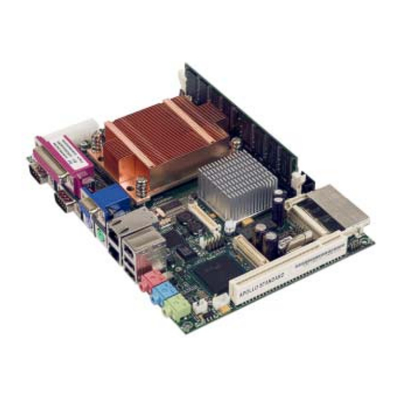
APOLLO user manual APOLLO ‘at a glance’ ATX power supply connector COM4 RS485/RS422 serial port IrDA connector System and CPU fans Front panel interface Primary IDE interface LVDS display interface COM3/COM4 RS232 serial ports LCD backlight connector Firewire port 1... - Page 7 Introduction VGA CRT Firewire Port 0 Line Out Parallel port Primary LAN Mic In COM1 Keyboard Secondary LAN USB1 Line In COM2 Mouse USB2 Side view showing connectors Issue G...
-
Page 8: Features
APOLLO user manual Features Processor • Intel Pentium M and Celeron M processor options. Chipset • North Bridge: Intel 82555GME. • South Bridge: Intel 82801DB/ICH4. • 400MHz processor side bus speed. System memory • Up to 1024MB PC2700 DDR DIMM. - Page 9 • Unique ID, tamper detection circuitry. • Trusted platform module using Atmel AT97SC3203 (TPM 1.2) V2Ix APOLLO only. • Provides hardware-based authentication of platform trust level, a secure store for private keys and an inbuilt encryption engine (compliant to TCG Spec. 1.2).
-
Page 10: Support Products
APOLLO. The TSC1 is designed to directly interface between four-, five- or eight-wire analogue touchscreens and a serial connection. A 1:1 ribbon cable can be used to connect directly to one of the RS232 ports on the APOLLO. A separate +5V connection is also required. -
Page 11: Development Kits
Introduction Development kits Eurotech offers development kits for the APOLLO board. A choice of three different configurations is available: • Windows XP Embedded contained on Flash disk module for the APOLLO V2Ix board ® and Windows XP Embedded contained on a CompactFlash card for the APOLLO V1Ix board. -
Page 12: Handling Your Board Safely
Do not incinerate, crush or otherwise damage the battery. Packaging Please ensure that, should a board need to be returned to Eurotech, it is adequately packed, preferably in the original packing material. Electromagnetic compatibility (EMC) The APOLLO is classified as a component with regard to the European Community EMC regulations and it is the user’s responsibility to ensure that systems using the board are... -
Page 13: Conventions
Introduction Conventions The following symbols are used in this guide: Symbol Explanation Note - information that requires your attention. Caution – proceeding with a course of action may damage your equipment or result in loss of data. Jumper is fitted. Jumper is not fitted. -
Page 14: Getting Started With Your Apollo
CMOS EEPROM. Identifying your APOLLO version To comply with the EU RoHS regulations, the APOLLO has been updated to version 2.x. Overall, the changes to the APOLLO functionality are minimal. However some of the component changes require new software to be loaded. -
Page 15: Cpu Configuration
Getting started with your APOLLO CPU configuration The APOLLO board has been specifically designed to support a range of Intel Pentium M and Celeron M mobile processors. The appropriate voltage and speed selections are configured during the boot process. No user configuration is required. -
Page 16: Installing A Processor
APOLLO user manual Installing a processor The standard and Gigabit variants of the APOLLO board have a zero insertion force PGA socket soldered to the board that accepts a range of Pentium M and Celeron M μFC-PGA processors. For a list of PGA processors, see page 91. -
Page 17: Connecting A Floppy Disk Drive
Getting started with your APOLLO Connecting a floppy disk drive The APOLLO supports one slimline floppy drive via a flat flex connector. A 26-way flat flex cable is used to provide a direct connection between the APOLLO board connector (see J27 –... -
Page 18: Connecting A Compactflash ® Card
Turning on your APOLLO By default, the APOLLO BIOS is set to enter a standby state when power is applied. This therefore requires the operator to turn the unit ON via a remote switch connected to the board. The APOLLO power button connection should be connected to a momentary ON push button switch;... -
Page 19: Using The Serial Interfaces (Rs232/Rs485/Irda)
Connecting a printer An enhanced printer port is incorporated into the APOLLO. This port can be used to support a Centronics-compatible printer or ECP/EPP bi-directional device. The port signals are routed to directly to a female DB25 connector. This socket is compatible with a standard printer port connector on a desktop machine. -
Page 20: Using The Usb Ports
Using the Ethernet interface The APOLLO V1Ix board provides two 10/100 Ethernet ports as standard. A factory build option on the V1Ix board is also available that provides one 10/100 Ethernet port and one 10/100/1000 Ethernet port, thus providing Gigabit Ethernet capability. -
Page 21: Led Indicators
LED indicators LED indicators Two new LEDs have been added to the APOLLO V2Ix board, these are used for a visual indication of the board status: Colour and position Purpose STANDBY Orange, situated Provides a visual indication to the user when 5V... -
Page 22: Jumpers And Connectors
APOLLO user manual Jumpers and connectors The following diagrams show the jumpers and connectors on the APOLLO. Click on any jumper or connector name for information. Issue G... - Page 23 Jumpers and connectors Issue G...
-
Page 24: Jumpers
APOLLO user manual Jumpers There are three jumper blocks on the APOLLO with a total of eight user-selectable jumper positions. These are summarized in the following table: Jumper Description Performs two functions: • PCI Grant/PCI Auxiliary power selection. • BIOS write protection. - Page 25 Jumpers and connectors JP1 PCI – PCI Grant/PCI auxiliary power selection Used to select the functionality of PCI slot pin A14. There are two options available: 3.3V PCI auxiliary voltage routed to the PCI slot, or GNT4 signal. GNT4 is made available to support a third PCI slot (via a riser card);...
- Page 26 APOLLO user manual JP2 on APOLLO V1Ix – User-configurable, CMOS reset and tamper detect This consists of four individual jumper positions. Two of these are user-configurable (USR1 and USR2). The third (CMOS) is used to clear the battery backed CMOS memory, whilst the fourth (TPM) provides a tamper detect option.
- Page 27 Changes to this jumper setting must only be made with board power completely removed. To do this you must remove the power cable. CMOS Description Reset CMOS memory. Default setting: CMOS unchanged. APOLLO V1Ix: TPM functionality jumper This position is used with the APOLLO TPM to provide future functionality. Issue G...
- Page 28 APOLLO user manual JP2 on APOLLO V2Ix – User-configurable, CMOS reset and tamper detect This consists of five individual jumper positions. Two of these are user-configurable (USR1 and USR2). The third (CMOS) is used to clear the battery backed CMOS memory, whilst the fourth (TPM) provides a tamper detect option.
- Page 29 Default setting: CMOS unchanged. APOLLO V2Ix: TPM jumper This position is used with the APOLLO TPM to provide future functionality. APOLLO V2Ix: Reset EE jumper This position is used to reload the default CMOS values from the system BIOS into the backup EEPROM and onboard CMOS.
- Page 30 APOLLO user manual JP3 – RS485/422 configuration This jumper is used to configure the RS485/422 serial interface. It can be used to enable/disable the RS485/422 termination resistors. See RS485/422 interfaces, page 107, for more details. The JP3 jumper is illustrated in the following diagram:...
-
Page 31: Connectors
Jumpers and connectors Connectors There are 34 connectors on the APOLLO that let you connect external devices such as keyboards, floppy disk drives, hard disk drives, printers etc. Connector Function See … Audio Line Out. Page 32. Audio Line In. - Page 32 APOLLO user manual Connector Function See … USB ports 3 to 4. Page 45. IEEE1394 port 1. Page 45. ® CompactFlash socket. Page 46. 184-pin DDR SDRAM DIMM Socket. J22A, J22B Serial ports 3 to 4. Page 47. Primary IDE.
- Page 33 Jumpers and connectors J1 - 3.5mm audio jack PC99 Colour: lime Connector: 2.0 mode Connector: 5.1 mode Line out left Surround out left Ring Line out right Surround out right Sleeve Ground Ground J2 - 3.5mm audio jack PC99 Colour: light blue Connector: 2.0 mode Connector: 5.1 mode Line in left Rear surround left...
- Page 34 APOLLO user manual J4A – IEEE1394 (Firewire) connector port 0 6-pin IEEE1394 connector. Signal name +12V (fused) Ground TPB0- TPB0+ TPA0- TPA0+ J4B and J4C – USB ports 1 and 2 USB type A connector. Signal name VBUS Data- Data+...
- Page 35 Jumpers and connectors J5A – Primary LAN APOLLO V1Ix: RJ-45 10/100Mb/s or optional 10/100/1000Mb/s. APOLLO V2Ix: RJ-45 10/100/1000Mb/s. Signal name Signal name (10/100) (10/100/1000) MD0+ MD0- MD1+ No Connect MD2+ No Connect MD2- MD1- No Connect MD3+ No Connect MD3- For a Gigabit Ethernet (10/100/1000) connection the network cable should be a CAT5 or above and include all four pairs.
- Page 36 APOLLO user manual J6A – VGA CRT connector DB15 Female PC99 Colour: Blue Signal name Signal name Green Blue No Connect Ground Ground Ground Ground +5V (Fused) Ground No Connect DDCSDA HSYNC VSYNC DDCSCL J6B – PS/2 keyboard Connector: 6-pin Mini-DIN...
- Page 37 Jumpers and connectors J7A – Parallel port (LPT1) DB25 female PC99 Colour: Maroon DB25 D-type socket Signal name STROBE ACKNOWLEDGE BUSY PAPER EMPTY SELECT AUTOFEED ERROR INIT SELECT IN Ground Ground Ground Ground Ground Ground Ground Ground Issue G...
- Page 38 APOLLO user manual J7B and J7C – COM1 and COM2 RS232 serial ports DB9 male PC99 Colour: Aqua Signal name Signal name Data Carrier Detect Receive Data (RX) (DCD) Transmit Data (TX) Data Terminal Ready (DTR) Ground Data Set ready (DSR)
- Page 39 Jumpers and connectors J10, J11 – system fan, CPU fan Both are 3-way 2.54mm (0.1") friction lock pin headers. The APOLLO supports PWM fan control and fan tachometer feedback. Connector: MOLEX 22-04-1031. Signal name Ground - PWM +12V Tachometer J12 – ATX power supply Molex 87427-2043, 20-way, 4.20mm (0.165") x 4.20mm (0.165") dual row header.
- Page 40 APOLLO user manual J13 – PCI connector 32-bit card edge connector. Three grant/request lines routed. Connector: 120-way PCI card edge connector (5V 32-bit 33MHz PCI socket). Side B Side A Side B Side A -12V /TRST AD17 AD16 TCK (GND)
- Page 41 Jumpers and connectors Side B Side A Side B Side A AD23 +3.3V AD01 AD00 Ground AD22 +5V(I/O) +5V(I/O) AD21 AD20 /ACK64 /REQ64 AD19 Ground +3.3V AD18 Slot IDSEL GNT/RQT AD27 AD29 AD31 4 (JP1 jumper selected) J14 – System control interface 10-way, 2.54mm (0.1") x 2.54mm (0.1") dual row header.
- Page 42 APOLLO user manual J15 – Backlight connector 6-way 2mm pitch shrouded header. Mating connector: JST PHR-6 Mating connector crimps: JST SPH-004T-P0.5S Signal name +12V Ground Backlight control Backlight En Ground J16 – Video option and USB ports 5/6 connector Hirose FX8C-80S-SV5.
- Page 43 Jumpers and connectors Signal name Signal name Ground DVOBCLK# USB overcurrent DVOBCLK DVO_REF DVOBHSYNC /RESET DVOBVSYNC Ground DVOBBLANK# ADDID7 DVOBFLDSTL ADDID6 Ground ADDID5 DVOCD11 ADDID4 DVOCD10 ADDID3 DVOCD9 ADDID2 DVOCD8 ADDID1 DVOCD7 ADDID0 DVOCD6 DVODETECT DVOCD5 DVOCFLDSTL DVOCD4 DVOBCINTR# DVOCD3 DVOBCCLKINT DVOCD2 Ground...
- Page 44 APOLLO user manual J17 – LVDS display interface (Dual channel) 40-way 2mm Hirose DF13-40DP-1.25V. Mating connector: Hirose DF13-40DS-1.25C Crimps: Hirose: DF13-2630SCFA For optimum performance of the LVDS interface a shielded twisted pair cable should be used. Signal name Signal name +3.3V...
- Page 45 Jumpers and connectors J18 – USB ports 3 and 4 10-way, 2.54mm (0.1") x 2.54mm (0.1") dual row header. Mating connector: Harwin M20-1070500 Mating connector crimps: Harwin M20-1180022 Signal name Signal name VBUS (port 3) VBUS (port 4) D- (port 3) D- (port 4) D+ (port 3) D+ (port 4)
- Page 46 APOLLO user manual J20 – CompactFlash socket ® Compact Flash CF+ type I/II socket. ® Connector: 50 pin right angle CompactFlash Signal name Signal name Ground /CE1 CF VCC /IOCS16 /CD2 /CD1 /CE2 /VS1 /IORD /IOWR /INTRQ CF VCC /VS2...
- Page 47 Jumpers and connectors J22A and J22B – COM3 and 4 RS232 serial ports 20 way, 2.54mm (0.1") x 2.54mm (0.1") boxed header. Mating connector: 71600-020. Pin (20-way Pin (9-way header) Signal name D-type plug) Data Carrier Detect (DCD) COM3 Data Set Ready (DSR) COM3 Receive Data (RX) COM3 Request To Send (RTS) COM3 Transmit Data (TX) COM3...
- Page 48 APOLLO user manual J23 – Primary IDE interface 40-way, 2.54mm (0.1") x 2.54mm (0.1") boxed header. Mating connector: 71600-040. Signal name Signal name /RESET Ground Ground Key (No pin) DREQ Ground /IOW Ground /IOR Ground /IOCHRDY Ground DACK Ground INTR...
- Page 49 Jumpers and connectors J24 – Front panel interface connector 26-way 2mm pitch shrouded header. Mating connector: Neltron 2417HJ-26-PHD Mating crimps: Neltron 2417TJ-PHD Signal name Signal name Ground CONTRAST ENABLE /IOW Ground (K) VCC_LCD (A) USER LED1 LED1 RES USER LED2 LED2 RES Ground +5V standby...
- Page 50 APOLLO user manual J26 – IrDA connector 4-way 2mm pitch shrouded header. Mating connector: JST PHR-4 Mating connector crimps: JST SPH-004T-P0.5S Signal name TX data Ground RX data J27 – Slimline floppy drive interface 26-way 1mm pitch FPC connector to support slimline floppy drive.
-
Page 51: Phoenixbios Features And Setup
PhoenixBIOS features and setup PhoenixBIOS features and setup The APOLLO is supplied with an embedded BIOS from Phoenix. The BIOS provides the following features : • Phoenix FirstBIOS Embedded Pro 4.0 Release 6.1. • Plug & Play (PCI, ISA) with full legacy IO support. -
Page 52: Phoenixbios Configuration
APOLLO user manual PhoenixBIOS configuration This section explains how to use the PhoenixBIOS setup program to modify BIOS settings and control the special features of your computer. To launch the PhoenixBIOS setup program: Turn on the computer. The Power On Self Test (POST) routine starts. A short while into this routine the following message is displayed: Press <F2>... -
Page 53: Control Keys
PhoenixBIOS features and setup Please note: • Information about the item currently highlighted is displayed on the right-hand side of the screen. • The BIOS settings are stored in battery-backed RAM that retains the system configuration information when the power is turned off. An onboard EEPROM is also provided to allow for batteryless operation and to reinitialize the CMOS settings if they become corrupted. -
Page 54: Main Menu
APOLLO user manual Main menu The Main menu is used to specify your basic system configuration: You can make the following selections from the Main menu: Field Explanation System Time, Used to set the system time and date. System Date Legacy Diskette A, Select the type of floppy disk drive(s) installed in your system. - Page 55 PhoenixBIOS features and setup Field Explanation System memory, The amount of conventional and extended memory (respectively) detected during boot-up. These values cannot be changed. Extended memory Boot Options Used to determine what happens when the computer is turned on. For example, you can choose to boot up more quickly by skipping certain tests.
- Page 56 APOLLO user manual The details you are prompted to specify for the drive are explained in the following table: Field Explanation Type Specify the type of drive installed as the selected master or slave drive. Use the + and - keys to choose a drive type.
- Page 57 PhoenixBIOS features and setup Field Explanation Multi-Sector Specify the number of sectors transferred per block, if required. You can choose 2, 4, 8 or 16 sectors. Alternatively, leave this Transfers Disabled if you don’t want to specify the number of sectors transferred.
- Page 58 APOLLO user manual Specifying boot options Each time the computer is switched on, a set of checks and procedures are carried out. You can control some of the events that take place as part of this sequence. For example, if speed of booting is a primary concern, you can minimize the number of tests carried out.
- Page 59 Network boot can Boot then be selected from the BIOS Boot menu. On the APOLLO V2Ix boards, this option has been moved to the IO Device Configuration → Ethernet Configuration screen, available from the Advanced menu...
-
Page 60: Advanced Menu
APOLLO user manual Advanced menu The Advanced menu is used to configure the advanced features available on your system’s chipset: The following table explains the settings you can choose: Field Explanation Installed O/S Choose the operating system that is to be used, e.g. WinXP. - Page 61 PhoenixBIOS features and setup Field Explanation Small LBA-Disk Determines whether CHS translation is made for LBA-capable hard disks with less than 1024 cylinders. CHS Translation You can choose either Yes (translate CHS for all LBA-capable disks) or No (translate CHS only if the hard disk drive has more than 1024 cylinders).
- Page 62 APOLLO user manual Specifying I/O device configuration settings The system communicates with external devices (such as printers) through Input/Output ports (I/O ports). You can configure the settings of these ports. For example, you can specify the I/O address or the interrupt line to be used by the I/O port.
- Page 63 Primary channel, the Secondary channel, Both or neither (choose Disabled). The APOLLO supports only a single IDE hard drive connection, which is the primary IDE adapter. However, the secondary IDE adapter must be enabled for the CompactFlash boot functionality to operate correctly.
- Page 64 APOLLO user manual Configuring serial ports To specify serial configuration settings, highlight Serial Configuration in the I/O Device Configuration menu and press Enter. The following screen is displayed: The details you are prompted to specify are explained in the following table:...
- Page 65 PhoenixBIOS features and setup Field Explanation Wake On Ring Choose whether the computer is to wake from standby/hibernation in response to a Ring Indicator (RI) signal from serial port COM1. Serial port COM2 Choose how this port is to be configured. The options available are the same as for Serial Port COM1, above.
- Page 66 APOLLO user manual Configuring parallel ports To specify parallel port configuration settings, highlight Parallel Port Configuration in the I/O Device Configuration menu and press Enter. The following screen is displayed: The details you are prompted to specify are explained in the following table:...
- Page 67 PhoenixBIOS features and setup Configuring USB ports To specify USB configuration settings, highlight USB Configuration in the I/O Device Configuration menu and press Enter. The following screen is displayed: The details you are prompted to specify are explained in the following table: Field Explanation Legacy USB...
- Page 68 APOLLO user manual Specifying keyboard feature settings You can control some aspects of the way a keyboard that is connected to the computer will work. For example, you may want users to hear a sound each time they press a key,...
- Page 69 PhoenixBIOS features and setup Specifying cache memory settings Using the memory cache can increase speed of access to data. When the memory cache is enabled, recently accessed data is stored in SRAM, which is faster than regular memory. Before accessing data in the regular memory, the CPU checks the cache. If the data is not held in the cache, the CPU accesses regular memory as usual.
- Page 70 APOLLO user manual Field Explanation Cache Video BIOS Choose whether to cache the video BIOS to improve area performance. You are offered Write Protect by default. This means the video BIOS is cached. (The video BIOS is always write protected.) If you don’t want to cache the video BIOS, choose uncached.
- Page 71 PhoenixBIOS features and setup The options available to select from the PCI Configuration sub-menu are explained in the following table: Field Explanation PCI/PNP ISA UMB Displays a sub-menu containing options you can use to reserve Region Exclusion blocks of memory for use by legacy ISA devices. See the following page for details.
- Page 72 APOLLO user manual PCI/PNP ISA IRQ resource exclusion settings When you select PCI/PNP ISA IRQ Resource Exclusion, the following screen is displayed: The IRQs in the system are listed. They are all Available by default. To reserve an IRQ, simply change the corresponding selection from Available to Reserved.
- Page 73 PhoenixBIOS features and setup CPU control settings You can specify settings that affect how the CPU operates. To specify CPU control settings, highlight CPU Control Sub-Menu in the Advanced menu and press Enter. The following screen is displayed: The details you are prompted to specify are explained in the following table: Field Explanation Enhanced Intel...
- Page 74 APOLLO user manual Field Explanation Thermal Control Circuit Used to enable the Thermal Control Circuit (TCC) portion of the Thermal Monitor feature of the CPU. You can choose: • : Thermal Monitor 1. This is the supported mode for Intel Celeron M processors. If the processor reaches its critical temperature (100°C/212°F), TM1 modulates the...
- Page 75 PhoenixBIOS features and setup MCH control settings You can specify settings that affect how the Memory Controller Hub operates. To specify MCH control settings, highlight MCH Control Sub-Menu in the Advanced menu and press Enter. The following screen is displayed: The details you are prompted to specify are explained in the following table: Field Explanation...
- Page 76 APOLLO user manual Video (Intel IGD) control settings You can specify settings that determine how the Internal Graphics Device operates. To specify video (Intel IGD) control settings, highlight Video (Intel IGD) Control Sub- Menu in the Advanced menu and press Enter. The following screen is displayed:...
- Page 77 PhoenixBIOS features and setup Field Explanation IGD – Device 2, Choose whether to enable or disable IGD - Device 2, Function 1. This is the second graphics controller on the Function 1 855GME chipset. This chipset has two graphics controllers integrated within one device, thus enabling two independent displays showing different images.
- Page 78 APOLLO user manual ACPI control settings You can control ACPI (Advanced Configuration and Power Interface) settings. To do this, highlight ACPI Control Sub-Menu in the Advanced menu and press Enter. The following screen is displayed: The details you are prompted to specify are explained in the following table:...
- Page 79 PhoenixBIOS features and setup Monitoring hardware You can monitor the temperature and voltage of hardware attached to your APOLLO. To do this, highlight Hardware Monitor in the Advanced menu and press Enter. The following screen is displayed: The system voltages and temperatures are shown in real-time. For each voltage required by components, the actual voltage being passed is displayed.
- Page 80 APOLLO user manual Maintaining system fan settings When you select Fan Speed Control from the Advanced menu, the following screen is displayed: The details you are prompted to specify are explained in the following table: Field Explanation CPU Fan speed The speed at which the processor fan is currently operating is shown in blue.
-
Page 81: Security Menu
PhoenixBIOS features and setup Security menu The Security menu is used to control access to the system and to set up reminders, for example, to prompt users to backup the system and check for viruses on a regular basis: The following table explains the security settings you can choose: Field Explanation Board ID... - Page 82 APOLLO user manual Field Explanation Set Supervisor Used to specify a password to access system setup. Once you’ve set a supervisor password, only those who enter this password Password can view the setup menus in full. To create a supervisor password, press Enter. The Set Supervisor Password dialog is displayed, ready for you to type the new password.
- Page 83 PhoenixBIOS features and setup Field Explanation Diskette access Choose the level of permission required to boot from or access the floppy disk. Select either User or Supervisor. Choose whether you want to remind users about virus checking. Virus check reminder A message is displayed each time the computer is turned on, until the user confirms that they have scanned for viruses.
-
Page 84: Power Menu
APOLLO user manual Power menu The Power menu is used to control power management. For example, you can specify how long the system must be idle before it goes into standby mode to conserve power. Power management reduces the amount of energy used after periods of inactivity:... - Page 85 • Power On to restart the computer automatically when power is restored. To allow the APOLLO board to boot automatically when AC power is applied, the Power On setting should be selected. Issue G...
-
Page 86: Boot Menu
APOLLO user manual Boot menu The Boot menu is used to specify the order of devices from which the computer attempts to load the operating system when it is switched on. To specify a device as a boot device, an operating system must be available on the device. - Page 87 PhoenixBIOS features and setup The following keys are available while working with the Boot menu: Explanation Enter Expands a device type for which there are multiple devices (indicated by ‘+’) to show a list of the devices of this type. Collapses a list of devices of a particular type (indicated by ‘-’).
-
Page 88: Exit Menu
APOLLO user manual Exit menu The Exit menu provides options for saving changes, discarding changes and exiting the PhoenixBIOS setup program: The following options are available: Field Explanation Exit Saving Saves any changes you have made, and exits the PhoenixBIOS Changes setup program. -
Page 89: Operating System Drivers
Please note: • Eurotech provides a Windows XP Embedded development kit which can be booted from a compact flash card or from a USB flash drive on the APOLLO V2Ix board. Please contact the Eurotech sales team for further information (see Eurotech Group Worldwide Presence, page 144). -
Page 90: Detailed Hardware Description
APOLLO user manual Detailed hardware description This section provides a detailed description of the functions provided by the APOLLO. This information may be required during development, once you have started adding extra peripherals or are starting to use some of the embedded features. -
Page 91: Processor
Other Intel Pentium M processors supporting a 400MHz FSB can also be used, although Intel does not guarantee their long-term availability. The APOLLO does not support the 533MHz front side bus Pentium M/ Celeron M processors, as these have different voltage requirements which are not supported. -
Page 92: Apollo Chipset
Memory interface The memory interface on the APOLLO board provides support for one ECC or non-ECC DDR (Double Data Rate) SDRAM 184-pin 2.5V unbuffered dual inline memory module (DIMM). Speeds PC1600 (200MHz), PC2100 (266MHz) and PC2700 (333MHz) are supported. - Page 93 UXGA (1600x1200). J16 board interface. This provides the capability to interface to a variety of Eurotech display option boards that have a TMDS/DVI, analogue CRT display interface, or a TV display interface via S-Video or composite video outputs.
-
Page 94: Display Modes
LVDS The GMCH has in-built dual channel ANSI/TIA/EIA –644-1995 compliant LVDS drivers. These allow for the direct connection of LVDS LCD panels to the APOLLO board. A high- speed surface mount connector interfaces these signals to an external cable. Spread spectrum clocking is also available to reduce EMI. - Page 95 Detailed hardware description Colour mapping The colour mapping of the APOLLO LVDS LCD interface is compatible with the VESA industry standard colour mapping for LCD displays. The figure below and the table that follows show the configuration for the colour bits in a three channel 6-bit/pixel LVDS bit...
-
Page 96: Windows Xp/Xp Embedded Video Drivers
This allows for features such as forcing the VGA output ON regardless of there being an attached display. IEGD Version 8.0 supports the Intel 855GME chipset used on the APOLLO board. Further information on the IEGD configuration tools are available at www.intel.com/go/iegd. -
Page 97: Video Option Boards
Currently an LVDS option board is not available. All option boards also break out the APOLLO’s additional USB5 and USB6 ports on a standard USB connection as used on the APOLLO board USB connector J18. -
Page 98: Ich4 (Io Controller Hub)
APOLLO user manual ICH4 (IO controller hub) The IO controller hub contains the primary PCI interface, LPC interface, USB 2.0, ATA-100, AC’97, Ethernet controller and other I/O functions. It communicates with the GMCH over an interconnect bus known as the hub interface. The ICH4 supports the following functions: •... -
Page 99: Firmware Hub
EEPROM. User jumper 1 (USR1 on JP2) is used for this purpose on the APOLLO V1Ix boards and a dedicated EE jumper (EE on JP2) is provided on the APOLLO V2Ix board. Refer to the... -
Page 100: Pci Local Bus
PCI Expansion connector The APOLLO provides a single 33MHz 32bit 5V PCI bus expansion connector. All PCI signals are 5V tolerant. The PCI expansion connector includes PCI auxiliary power for devices requiring power during ACPI standby (S3) and soft off (S5) modes. The PCI PME# power management signal is also provided for device wakeup. -
Page 101: Ethernet Controllers
Detailed hardware description Dual Slot PCI riser A dual slot 1U height PCI riser card has been designed to interface to the APOLLO board. This is used to provide additional PCI slots to support up to two bus master PCI expansion cards. -
Page 102: Secondary Network Interface
86, for further information. Ethernet cables To provide the best immunity to external interference a shielded twisted pair cable is recommended for use with the APOLLO board. For Gigabit Ethernet this should be rated as a CAT5E or higher cable. Issue G... -
Page 103: Ide Interface
Detailed hardware description IDE interface The APOLLO provides a single IDE channel capable of Ultra ATA 100 operation. This is listed as the primary IDE interface in the BIOS. The primary IDE interface can support several types of data transfers: •... -
Page 104: Real Time Clock
If the USB voltage is short circuited or more than 500mA is drawn from either supply the switch turns off the power supply and automatically protects the device and board. The VBUS signal is derived from the ATX +5V supply via the APOLLO. Real Time Clock The Real Time Clock (RTC) module provides a battery backed-up date and time-keeping device. -
Page 105: Watchdog Timer
Detailed hardware description Watchdog timer The APOLLO provides a Maxim MAX6369KA watchdog timer with a pin-selectable timeout of 1ms to 60 seconds. This can be used to generate a complete hardware system reset when an error causes a system lockup. By default, the watchdog timer is disabled and once enabled must be triggered within the timeout period specified. -
Page 106: Ac'97 Audio Codec
APOLLO user manual The connections made to J14 are shown in the following system control interface diagram. For further connector details, see page 41. TAMPER DETECT ON/OFF RESET SPEAKER AC’97 audio CODEC The VIA VT1616 AC’97 audio CODEC provides six channel outputs with 18-bit resolution allowing the part to support 5.1 surround sound specifications. -
Page 107: Pci Dual Uart
Detailed hardware description PCI dual UART An Exar XR17D152 PCI based dual UART is provided on the APOLLO board, this supports COM3 and COM4. COM3 is configured as a standard RS232 port, whilst COM4 is configured as a software selectable RS232, RS485 or RS422 port. - Page 108 APOLLO user manual RS485/422 interface configuration The following table lists the different RS422/RS485 operating modes supported by the APOLLO and the BIOS configurations required to support these operating modes. RS422 POINT-TO-POINT RS422 MULTI-DROP RS485 MULTI-DROP Number of Wires Number of Wires...
-
Page 109: Super Io
Detailed hardware description Super IO On the APOLLO V1Ix boards, an SMSC LPC47M292 Super IO controller provides legacy IO support. On the APOLLO V2Ix boards, an SMSC SCH3112 provides the SuperIO support. On both boards the SuperIO resides on the LPC bus and provides: •... -
Page 110: Irda/Ask-Ir
100nF Parallel port The APOLLO provides a parallel port that can be used to connect an external printer, tape drive, disk drive, scanner etc., or can provide additional digital I/O capability. The port is both IBM XT/AT and IEEE1284 compatible. It supports Standard Parallel Port (SPP), Enhanced Parallel Port (EPP) and Extended Capabilities Port (ECP) modes and is compliant with the IEEE1284 specification. -
Page 111: Floppy Disk Controller
The true CMOS 765B core guarantees 100% IBM PC XT/AT compatibility in addition to providing data overflow and underflow protection. The APOLLO allows for an interface to a single slimline floppy drive using a 26-way flat flex cable. For connector details, see page 50. -
Page 112: Keyboard And Mouse Controller
PC Card standards and compatible with the CompactFlash CF+ host specification. The APOLLO has a single CF+ Type II CompactFlash socket that supports 3.3V and 5V Type I/II CompactFlash cards, providing support for a wide variety of flash, wireless, serial and networking cards. -
Page 113: Trusted Platform Module
ACPI low power sleep states. As a minimum, the APOLLO requires the ATX power supply, 5V, 5V standby, 3.3V and 12V power rails. The –5V is not used and the –12V is only required if a PCI card used with the APOLLO requires this power rail. -
Page 114: Front Panel Interface
Please contact Eurotech support for the latest driver. LCD interface The APOLLO board provides an LCD interface that can be used to connect to an HD44780 or similar LCD character display. A contrast voltage and diode-protected LED backlight power supply are also provided. -
Page 115: Registers V1Ix Board
Detailed hardware description Registers V1Ix board Data direction register IO address Description Base address + 23h Output type select Base address + 24h 1 = Open Drain Base address + 25h 2 = Push Pull Base address + 26h Reserved Base address + 27h 00 = GPIO Base address + 28h... - Page 116 APOLLO user manual LCD control bits, GPIO1 and GPIO2 data registers The LCD control bits correspond with those used on most standard LCD character displays. GPIO1 and GPIO2 are standalone GPIO that are not used by the LCD interface; the data direction register description describes the configuration of the GPIO.
-
Page 117: Registers V2Ix Board
Detailed hardware description Registers V2Ix board Data direction register IO address Description Base address + 23h Output type select Base address + 24h 1 = Open Drain Base address + 25h 0 = Push Pull Base address + 26h Reserved Base address + 27h 00 = GPIO Base address + 29h... - Page 118 APOLLO user manual LCD control bits data register The LCD control bits correspond with those used on most standard LCD character displays and have the following. RS – Register Select (Command or Data) IOW – IO Read/Write ENABLE – Data enable signal...
-
Page 119: User Leds
LEDs fall into this category, the exception being blue LEDs which require a higher forward voltage, typically 4V to be illuminated. The following figure shows the correct connection of a user supplied LED a 330Ω resistor is provided on the APOLLO board so that a direct LED connection can be made. Issue G... - Page 120 Connector J24 provides an interface to the system management bus commonly known as the SMBUS. Below is a list of devices that are present on the APOLLO board and their corresponding 7-bit SMBUS address, care should be taken to ensure that any new device added to the bus does not conflict with existing devices as this may cause boot issues.
-
Page 121: Unique Id
Detailed hardware description Unique ID A Unique ID is provided on the APOLLO using the DS2401 enhanced silicon serial number IC. The DS2401 consists of a factory-lasered 64 bit ROM that includes a unique 48 bit serial number, an 8 bit CRC and an 8 bit family code (01h). The DS2401 has been... -
Page 122: System Resources
APOLLO user manual System resources I/O map IO location Functional block DMA controller 1 0000H – 001FH 0020H – 002DH Programmable Interrupt controller 1 002EH – 002FH LPC SuperIO index registers Programmable Interrupt controller 1 0030H – 003DH 0040H – 0043H System timer 0 0050H –... -
Page 123: System Memory Map
These locations are based on the BIOS default setups; the memory location of these devices will change if the default BIOS options for the IO ports are modified. Interrupts The APOLLO supports two different interrupt modes: • The standard dual 8259 programmable interrupt controller providing 15 interrupt connections. - Page 124 APOLLO user manual Master 8259 input Interrupt source Internal connection to counter 0. Keyboard controller (via SERIRQ). 8259 slave connection. IRQ3: configurable. Default connection: Serial port COM2. IRQ4: configurable. Default connection: Serial port COM1. IRQ5: configurable. SERIRQ to floppy disk controller.
- Page 125 Detailed hardware description APIC: Advanced Programmable Interrupt Controller Use of the APIC interrupt mode is enabled using the field APIC - IO APIC Mode, available from the ACPI Control sub-menu in the BIOS. See page for further details. Interrupt source Cascade from 8259 Keyboard controller 8259 counter 0...
-
Page 126: Dma Mapping
APOLLO user manual DMA mapping Mapping Default use LPT1 Floppy Disk Controller Available Cascade from DMA1 Available Available Available Default DMA mappings, changes to the BIOS configuration may modify these mappings. Issue G... -
Page 127: Appendix A - Specification
130nm processors with 400MHz FSB. • Intel Ultra Low Voltage Pentium M 479-pin μFCBGA package with 400MHz FSB. The APOLLO Celeron M 600MHz variant has a non- interchangeable board mounted 600MHz Celeron M processor. Cache Pentium M 130nm, 1MB L2 CPU Integrated... - Page 128 ISIS user manual IDE drive support Primary IDE Controller onboard ICH4. Supports Ultra ATA100/66/33, PIO and 8237 style DMA transfers. 40-way 2.54mm IDE connector support provided. Floppy drive support 100% IBM compatible 2.88MB floppy drive controller with integrated digital separator and dual floppy drive support I/O ports One IEEE1284 parallel port (ECP, EPP and SPP modes).
- Page 129 Appendix A – Specification Temperature Fan-less operation (passive cooling): -20°C to +65°C (based on Pentium M CPU running at 600MHz). Operating (active cooling): -20°C to +65°C (based on Pentium M CPU running at 1.6GHz). Storage -40°C (-40°F) to +70°C (158°F). Humidity 10% to 90% RH (non-condensing).
-
Page 130: Appendix B - Apollo Mechanical Diagram
ISIS user manual Appendix B – APOLLO mechanical diagram Issue G... - Page 131 Appendix B – APOLLO mechanical diagram 18.0 x 26.4 16.2 x 27.4 Ø10.00 Ø12.00 Ø8.20 ( 3 off ) Ø12.00 ( 2 off ) 25.35 ADD CARD PLATE POSITION 32.00 25.97 25.70 27.10 19.80 21.40 6.30 6.20 6.50 0.00 OFFSET OF ADD CARD...
- Page 132 5.4mm to prevent the standoff from being drawn into the mounting hole. If this configuration is used and a large CPU heatsink is used with the APOLLO board then the standard heatsink backing plate is not required and the following configuration should used.
-
Page 133: Appendix C - Tft Display Interface Cable
Appendix C – TFT display interface cable Appendix C – TFT display interface cable The following table shows the connection details for the AU Optronics 15 LCD flat panel " display G150XG01 used in the development kits: APOLLO J17 DF-14H-20P-1.25H Panel signal name +3.3V +3.3V Ground... - Page 134 ISIS user manual The following table shows the connection details for the TDK CXA-P1612-VJL backlight inverter cable. This configuration allows for PWM based brightness control from the APOLLO board. See J15 – Backlight connector, page 42, and LCD backlight connector, page for further details.
-
Page 135: Appendix D - Apollo Usb 5/6 Breakout
Appendix D – APOLLO USB 5/6 breakout Appendix D – APOLLO USB 5/6 breakout A board has been designed to provide a breakout option for the USB 5 and 6 ports which are interfaces via the connector J16. J2 – USB ports 5 and 6 10-way, 2.54mm (0.1") x 2.54mm (0.1") dual row header. -
Page 136: Appendix E - Dvi Video Option Board
The DVI video option board provides the ability to connect single channel DVI 1.0 compliant display devices to the APOLLO board. This can be used in conjunction with the LVDS or VGA display interfaces to provide dual display capabilities. The following connections refer to pinouts on the DVI board. - Page 137 Appendix E – DVI video option board J3 – USB ports 5 and 6 10-way, 2.54mm (0.1") x 2.54mm (0.1") dual row header. Mating connector: Harwin M20-1070500 Mating connector crimps: Harwin M20-1180022 Signal name Signal name VBUS (port 5) VBUS (port 6) D- (port 5) D- (port 6) D+ (port 5)
-
Page 138: Appendix F - Tv Out Video Option Board
ISIS user manual Appendix F – TV out video option board The TV out video option board provides the ability to encode the DVO output for S-Video and composite video outputs in a wide variety of broadcast quality NTSC and PAL video output modes. - Page 139 Appendix F – TV out video option board J2 – S-Video Connector: 4-pin Mini-DIN, Kycon KMDGX-4S-BS Signal name Ground (Y) Ground (C) Y - Intensity (Luminance) C – Colour (Chrominance) J4 – USB ports 5 and 6 10-way, 2.54mm (0.1") x 2.54mm (0.1") dual row header. Mating connector: Harwin M20-1070500 Mating connector crimps: Harwin M20-1180022 Signal name...
-
Page 140: Appendix G - Vga Option Board
VGA output. The option board uses the APOLLO LVDS data and converts this to a standard VGA monitor output. The display resolutions supported are 800x600, 1024x768 and 1280x1024 at a 60Hz refresh rate. - Page 141 Appendix G – VGA option board J2 – LVDS input interface (single channel) 20-way 2mm Hirose DF13-20DP-1.25V. Mating connector: Hirose DF13-20DS-1.25C Crimps: Hirose: DF13-2630SCFA Signal name Signal name +3.3V +3.3V LVDS_D0- LVDS_D0+ LVDS_D1- LVDS_D1+ LVDS_D2- LVDS_D2+ LVDS_CLK- LVDS_CLK+ DDC_CLK DDC_DATA J4 –...
-
Page 142: Appendix H - Reference Information
ISIS user manual Appendix H – Reference information Product information Product notices, updated drivers, support material: www.eurotech.com PCI special interest group PCI Bus specification and list of manufacturers: www.pcisig.org USB information Universal Serial Bus (USB) specification and product information: www.usb.org... -
Page 143: Appendix I - Rohs-6 Compliance - Materials Declaration Form
APOLLO-GIGABIT-R6 6580-00664-001-201 Eurotech has based its material content knowledge on a combination of information provided by third parties and auditing our suppliers and sub-contractor’s operational activities and arrangements. This information is archived within the associated Technical Construction File. Eurotech has taken reasonable steps to provide representative and accurate information, though may not have conducted destructive testing or chemical analysis on incoming components and materials. -
Page 144: Eurotech Group Worldwide Presence
Eurotech Group Worldwide Presence AMERICAS EUROPE ASIA North America Central & Southern Europe Japan EUROTECH USA EUROTECH Italy ADVANET US toll free +1 800.541.2003 tel. +39 0433.485.411 tel. +81 86.245.2861 tel. +1 301.490.4007 fax +39 0433.485.499 fax +81 86.245.2860 fax +1 301.490.4582 e-mail: sales-it@eurotech.com... - Page 145 www.eurotech.com...
Need help?
Do you have a question about the Apollo and is the answer not in the manual?
Questions and answers