
Related Manuals for Eurotech ALUDRA


Summary of Contents for Eurotech ALUDRA
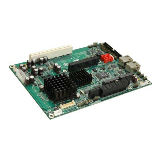
- Page 1 USER MANUAL ALUDRA 5.25" Single Board Computer Issue A - November 2009 - ETH_ALUDRA_USM DIGITAL TECHNOLOGIES FOR A BETTER WORLD www.eurotech.com...
- Page 2 ALUDRA user manual Life support policy Eurotech products are not authorized for use as critical components in life support devices or systems without the express written approval of Eurotech. Warranty For Warranty terms and conditions users should contact their local Eurotech Sales Office.
-
Page 3: Table Of Contents
Important user information ......................4 Safety notices and warnings ....................4 Life support policy ......................6 WEEE..........................6 RoHS ..........................6 Introduction .............................7 ALUDRA ‘at a glance’......................8 Detailed Specifications........................12 Board Dimensions......................12 External Interface Panel Dimensions ................13 Data Flow .........................13 Embedded ALUDRA Processor..................14 Intel 945GSE Northbridge Chipset ...................16 ®... -
Page 4: Important User Information
The safety precautions listed below represent warnings of certain dangers of which Eurotech is aware of. You, as the user of the product, should follow these warnings and all other safety precautions necessary for the safe operation of the equipment in your operating environment. - Page 5 To avoid damage caused by ESD (Electro Static Discharge), always use appropriate antistatic precautions when handing any electronic equipment. Packaging Please ensure that, should a board need to be returned to Eurotech, it is adequately packed, preferably in the original packing material. Electromagnetic compatibility (EMC) The ALUDRA is classified as a component with regard to the European Community EMC regulations and it is the user’s responsibility to ensure that systems using the board are...
-
Page 6: Life Support Policy
ALUDRA user manual Life support policy Eurotech products are not authorized for use as critical components in life support devices or systems without the express written approval of Eurotech. WEEE The information below is issued in compliance with the regulations as set out in the 2002/96/EC directive, subsequently superseded by 2003/108/EC. -
Page 7: Introduction
The ALUDRA 5.25" motherboard utilises a 45nm Intel Atom™ N270 processor with a 1.60 GHz clock, a 533 MHz FSB and a 512 KB L2 cache. The ALUDRA also supports one 200-pin 533MHz 2.0GB (max.) DDR2 SDRAM SO-DIMM. The board comes with one LVDS connector and supports 18-bit dual-channel LVDS screens. -
Page 8: Aludra 'At A Glance
ALUDRA user manual ALUDRA ‘at a glance’ The ALUDRA has a wide variety of peripheral interface connectors. Figure 2 is a labelled photo of the peripheral interface connectors on the ALUDRA. Figure 2: ALUDRA Overview [Front View] Figure 3: ALUDRA Overview [Solder Side]... - Page 9 Introduction ALUDRA Peripheral Connectors and Jumpers The ALUDRA has the following connectors on-board: One ATX power connector for +5V and +12V supplies One Audio connector One ATX power control connector One Backlight inverter connector ® ...
- Page 10 ALUDRA user manual Technical Specifications ALUDRA technical specifications are listed in Table 1. Specification ALUDRA ® 45 nm 1.6 GHz Intel Atom™ N270 System CPU Front Side Bus (FSB) 533 MHz ® System Chipset Northbridge: Intel 945GSE ® Southbridge: Intel...
- Page 11 Introduction Power Supply ATX and AT power supported ® Power Consumption 5V @ 2.89A, 12V@0.04A (1.6 GHz Intel Atom™ N270 CPU with one 1 GB DDR2 SO-DIMM) Temperature 0ºC – 60ºC (32ºF - 140ºF) Humidity (operating) 5%~95% non-condensing Dimensions (LxW) 203 mm x 146 mm 1000g/400g Weight (GW/NW)
-
Page 12: Detailed Specifications
ALUDRA user manual Detailed Specifications Board Dimensions The dimensions of the board are listed below: Length: 203 mm Width: 146 mm Figure 4: ALUDRA Dimensions (mm) Issue A... -
Page 13: External Interface Panel Dimensions
Detailed Specifications External Interface Panel Dimensions External peripheral interface connector panel dimensions are shown in Figure 5. Figure 5: External Interface Panel Dimensions (mm) Data Flow Figure 6 shows the data flow between the two on-board chipsets and other components installed on the motherboard and described in the following sections of this chapter. -
Page 14: Embedded Aludra Processor
ALUDRA user manual Embedded ALUDRA Processor ® The ALUDRA comes with an embedded 45 nm 1.60 GHz Intel Atom™ processor N270. The processor supports a 533 MHz FSB and has a 1.6 GHz 512 KB L2 cache. The low power processor has a maximum power of 2.5 W. The processor is shown in Figure 7 below. - Page 15 Front Side Bus (FSB) ® ® The Intel Atom™ processor on the ALUDRA is interfaced to the Intel 945GSE through a 533 MHz front side bus (FSB). The FSB is shown in Figure 8 below. Figure 8: Front Side Bus...
-
Page 16: Intel 945Gse Northbridge Chipset
945GSE is interfaced to the processor through a 533 MHz FSB. ® Intel 945GSE DDR2 Controller There is one 200-pin DDR2 SO-DIMM socket on the ALUDRA. The socket supports DDR2 SO-DIMM with the following specifications: Maximum Memory supported 2 GB ... - Page 17 Detailed Specifications Microsoft DirectX* 9.1 operating system Intermediate Z in Classic Rendering Internal Graphics Display Device States: D0, D1, D3 Graphics Display Adapter States: D0, D3. Figure 10: CRT, LVDS and TV-Out Connectors Analogue CRT Graphics Mode The analogue CRT bus is interfaced to an on-board 10-pin connector.
- Page 18 ALUDRA user manual TV Out Interface The TV Out interface (Figure 10) has the following features. Three integrated 10-bit DACS Overscaling NTSC/PAL Component, S-Video and Composite Output interfaces HDTV support: 480p/720p/1080i/1080p Issue A...
-
Page 19: Intel ® Ich7-M Southbridge Chipset
Integrated SATA host controller with DMA operations interfaced to two SATA connectors on the ALUDRA Supports the four USB 2.0 devices on the ALUDRA with four UHCI controllers and one EHCI controller Complies with System Management Bus (SMBus) Specification, Version 2.0 ... - Page 20 ALUDRA user manual ® Intel ICH7-M Audio Codec ’97 Controller The Audio Codec ’97 (AC’97) controller integrated into the ICH7-M complies with AC’97 Component Specification, Version 2.3. The AC’97 controller is integrated to a RealTek ALC655 audio codec. The RealTek ALC655 is in turn connected to on-board audio connectors, which are then connected to compliant audio devices.
- Page 21 Detailed Specifications ® Intel ICH7-M IDE Interface The integrated IDE interface on the ICH7-M southbridge supports two IDE hard disks and ATAPI devices. The IDE connector is shown in Figure 12 below. Figure 12: IDE Connector PIO IDE transfers up to 16MB/s and Ultra ATA transfers of 100MB/s. The integrated IDE interface is able to support the following IDE HDDs: ...
- Page 22 ALUDRA user manual ® Intel ICH7-M PCI Interface The PCI interface on the ICH7-M is compliant with the PCI Revision 2.3 implementation. Some of the features of the PCI interface are listed below. PCI Revision 2.3 compliant 33MHz ...
- Page 23 Detailed Specifications ® Intel ICH7-M PCIe Bus ® The Intel ICH7-M southbridge chipset has four PCIe lanes. Two of the four PCIe lanes are interfaced to PCIe GbE controller. A third PCIe lane is interfaced to a PCIe mini socket. PCIe GbE Ethernet Two PCIe lanes are connected to two Realtek RTL8111C PCIe GbE controllers shown in Figure 14 below.
- Page 24 ALUDRA user manual Fully compliant with IEEE 802.3, IEEE 802.3u, IEEE 802.3ab Supports IEEE 802.1P Layer 2 Priority Encoding Supports IEEE 802.1Q VLAN tagging Serial EEPROM Transmit/Receive on-chip buffer support Supports power down/link down power saving ...
- Page 25 The integrated SATA controller on the ICH7-M supports up to four SATA drives with independent DMA operations. Two SATA controllers are connected to two SATA connectors on the ALUDRA. The SATA connectors are shown in Figure 16. Figure 16: SATA Connectors SATA controller specifications are listed below.
- Page 26 Up to six high-speed, full-speed or low-speed USB devices are supported by the ICH7-M on the ALUDRA. High-speed USB 2.0, with data transfers of up to 480MB/s, is enabled with the ICH7-M integrated Enhanced Host Controller Interface (EHCI) compliant host controller.
-
Page 27: Lpc Bus Components
Detailed Specifications LPC Bus Components The ICH7-M LPC bus is connected to components listed below: Super I/O chipset LPC Serial Port Chipset iTE IT8718F Super I/O Chipset The iTE IT8718F Super I/O chipset is connected to the ICH7-M through the LPC bus. Figure 18: Super I/O The iTE IT8718F is an LPC interface-based Super I/O device that comes with Environment Controller integration. - Page 28 ALUDRA user manual Super I/O 16C550 UARTs The on-board Super I/O has two integrated 16C550 UARTs that can support the following: Two standard serial ports (COM1 and COM2) IrDa 1.0 and ASKIR protocols Another chipset connected to the LPC bus provided connectivity to another two serial port connectors (COM3 and COM4).
-
Page 29: Environmental And Power Specifications
CPU. Heat sinks are also mounted on the Northbridge and Southbridge chipsets to ensure the operating temperature of these chips remain low. Power Consumption Table 3 shows the power consumption parameters for the ALUDRA running with a 1.6 ® GHz Intel Atom™... -
Page 30: Unpacking
When the ALUDRA is unpacked, please follow anti-static precautions and make sure the packing box is facing upwards so the ALUDRA does not fall out of the box. No cables are provided with the ALUDRA. A list of available cables and modules for the ALUDRA can be found in Appendix E –... -
Page 31: Connectors
Figure 19: Connector and Jumper Locations [Front Side] Figure 20: Connector and Jumper Locations [Solder Side] Table 4 shows a list of the peripheral interface connectors on the ALUDRA. Detailed descriptions of these connectors can be found below. Issue A... - Page 32 ALUDRA user manual Connector Type Label +5V and +12V power source connector 4-pin connector ATX power control connector 3-pin wafer Audio connector 9-pin header Backlight inverter connector 5-pin wafer INVERTER1 ® CompactFlash socket 50-pin CF socket CRT connector 10-pin box header...
- Page 33 Connectors External Interface Panel Connectors Table 5 lists the rear panel connectors on the ALUDRA. Detailed descriptions of these connectors can be found in the External Peripheral Interface Connector Panel, page 58. Connector Type Label Ethernet connector RJ-45 LAN1 Ethernet connector...
- Page 34 The ATX power supply enable connector enables the ALUDRA to be connected to an ATX power supply. In default mode, the ALUDRA can only use an AT power supply. To enable an ATX power supply the AT Power Select jumper must also be configured. See Installation, page for more details.
- Page 35 Connectors Audio Connector (9-pin) CN Label: CN Type: 9-pin header (2x5) CN Location: See Figure 23 CN Pinouts: See Table 8 The 9-pin audio connector is connected to external audio devices including speakers and microphones for the input and output of audio signals to and from the system. LINEOUTR LINEOUTL MICIN...
- Page 36 See Figure 24 CN Pinouts: See Table 9 The backlight inverter connector provides the backlight on the LCD display connected to the ALUDRA with +12V of power. Figure 24: Panel Backlight Connector Pinout Locations PIN NO. DESCRIPTION LCD Backlight Control (PWM)
- Page 37 50-pin header (2x25) CN Location: See Figure 25 CN Pinouts: See Table 10 A CF Type II memory card is inserted to the CF socket on the solder side of the ALUDRA. Figure 25: CF Card Socket Location Issue A...
- Page 38 ALUDRA user manual PIN NO. DESCRIPTION PIN NO. DESCRIPTION CARD_DETECT1# DATA 3 DATA 11 DATA 4 DATA 12 DATA 5 DATA 13 DATA 6 DATA 14 DATA 7 DATA 15 CS0# CS1# IOR# IOW# CSEL# RESET# IORDY ADDR2 SDREQ ADDR 1...
- Page 39 Connectors CRT Connector CN Label: CN Type: 10-pin box header (2x5) CN Location: See Figure 26 CN Pinouts: See Table 11 The 2x5 CRT pin connector provides connectivity to an external VGA port enabling the system to be connected to a standard CRT screen. Figure 26: VGA Connector Pinout Locations PIN NO.
- Page 40 ALUDRA user manual Digital Input/Output (DIO) Connector CN Label: DIO1 CN Type: 10-pin header (2x5) CN Location: See Figure 27 CN Pinouts: See Table 12 The digital input/output connector is managed through a Super I/O chip. The DIO connector pins are user programmable.
- Page 41 Connectors Fan Connector (+12V, 3-pin) CN Label: CN Type: 3-pin wafer (1x3) CN Location: See Figure 28 CN Pinouts: See Table 13 The cooling fan connector provides a 12V, 500mA current to the cooling fan. The connector has a "rotation" pin to get rotation signals from fans and notify the system so the system BIOS can recognize the fan speed.
- Page 42 ALUDRA user manual Front Panel Connector (8-pin) CN Label: F_PANEL1 CN Type: 8-pin header (2x4) CN Location: See Figure 29 CN Pinouts: See Table 14 The front panel connector connects to external switches and indicators to monitor and controls the motherboard. These indicators and switches include: ...
- Page 43 CN Type: 44-pin box header (2x22) CN Location: See Figure 30 CN Pinouts: See Table 15 One 44-pin IDE device connector on the ALUDRA supports connectivity to two hard disk drives. Figure 30: Secondary IDE Device Connector Locations Issue A...
- Page 44 ALUDRA user manual PIN NO. DESCRIPTION PIN NO. DESCRIPTION RESET# DATA 7 DATA 8 DATA 6 DATA 9 DATA 5 DATA 10 DATA 4 DATA 11 DATA 3 DATA 12 DATA 2 DATA 13 DATA 1 DATA 14 DATA 0...
- Page 45 Connectors Infrared Interface Connector (5-pin) CN Label: CN Type: 5-pin header (1x5) CN Location: See Figure 31 CN Pinouts: See Table 16 The infrared interface connector supports both Serial Infrared (SIR) and Amplitude Shift Key Infrared (ASKIR) interfaces. Figure 31: Infrared Connector Pinout Locations PIN NO.
- Page 46 ALUDRA user manual Keyboard/Mouse Connector CN Label: CN Type: 6-pin wafer (1x6) CN Location: See Figure 32 CN Pinouts: See Table 17 The keyboard and mouse connector can be connected to a standard PS/2 cable or PS/2 Y-cable to add keyboard and mouse functionality to the system.
- Page 47 Connectors LVDS LCD Connector CN Label: LVDS1 CN Type: 30-pin crimp (3x10) CN Location: See Figure 33 CN Pinouts: See Table 18 The 30-pin LVDS LCD connectors can be connected to single channel or dual channel, 18-bit LVDS panel. Figure 33: LVDS LCD Connector Pinout Location PIN NO.
- Page 48 ALUDRA user manual Parallel Port Connector CN Label: CN Type: 26-pin header (2x13) CN Location: See Figure 34 CN Pinouts: See Table 19 The 26-pin parallel port connector connects to a parallel port connector interface or some other parallel port device such as a printer.
- Page 49 Connectors SDVO Connector CN Label: CN Type: 47-pin connector (1x47) CN Location: See Figure 35 CN Pinouts: See Table 20 The SDVO (Serial Digital Video Out) port B connector supports additional video signalling interfaces. Figure 35: SDVO Connector Pinout Locations Issue A...
- Page 50 ALUDRA user manual PIN NO. DESCRIPTION PIN NO. DESCRIPTION SDVOC_CLK- SDVOB_BLUE- SDVOC_CLK+ SDVOB_BLUE+ SDVOC_GREEN- SDVOB_RED- SDVOC_GREEN+ SDVOB_RED+ SDVOB_CLK- SDVO1_STALL- SDVOB_ CLK+ SDVO1_STALL+ SDVOB_GREEN- SDVO_TVCLKIN- SDVOB_GREEN+ SDVO_TVCLKIN+ SDVOC_INT+ SDVO_CLK SDVOC_INT+ SDVO_DATA PCIRST SDVOB_INT+ +5VS SDVOB_INT+ +5VS +5VS SDVOC_BLUE- SDVOC_BLUE+ SDVOC_RED- SDVOC_RED+...
- Page 51 Connectors SATA Drive Connectors CN Label: SATA1 and SATA2 CN Type: 7-pin SATA drive connectors CN Location: See Figure 36 CN Pinouts: See Table 21 The two SATA drive connectors are each connected to a first generation SATA drive. First generation SATA drives transfer data at speeds as high as 150 Mb/s.
- Page 52 ALUDRA user manual SATA Power Connectors CN Label: CN1 and CN2 CN Type: 2-pin wafer CN Location: See Figure 37 CN Pinouts: See Table 22 The SATA power connector provides +5V power to the SATA drive. Figure 37: SATA Power Connector Locations PIN NO.
- Page 53 Connectors Serial Port Connectors (COM 1 ~ COM 4) CN Label: COM1, COM2, COM3 and COM4 CN Type: 10-pin header (2x5) CN Location: See Figure 38 CN Pinouts: See Table 23 The 10-pin serial port connector provides a RS-232 serial communications channel. The COM serial port connectors can be connected to external RS-232 serial port devices.
- Page 54 ALUDRA user manual COM 3 RS-422/485 Connector CN Label: CN Type: 6-pin header (2x3) CN Location: See Figure 39 CN Pinouts: See Table 24 The COM 3 serial port can be set for RS-422/485 connectivity by on-board jumper (refer COM 3 Function Select Jumper, page 67).
- Page 55 Connectors Trusted Platform Module (TPM) Connector CN Label: TPM1 CN Type: 40-pin header (2x20) CN Location: See Figure 40 CN Pinouts: See Table 25 The Trusted Platform Module (TPM) connector secures the system on bootup. Figure 40: TPM Connector Pinout Locations PIN NO.
- Page 56 ALUDRA user manual TV Out Connector CN Label: CN Type: 6-pin header (2x3) CN Location: See Figure 41 CN Pinouts: See Table 26 The 2x3 pin TV out connector connects to a TV output by using an S-Video or RCA connector.
- Page 57 Connectors USB Connectors (Internal) CN Label: USB1, USB2 and USB3 CN Type: 8-pin header (2x4) CN Location: See Figure 42 CN Pinouts: See Table 27 The 2x4 USB pin connectors each provide connectivity to two USB 1.1 or two USB 2.0 ports.
-
Page 58: External Peripheral Interface Connector Panel
ALUDRA user manual External Peripheral Interface Connector Panel F igure 43 shows the ALUDRA external peripheral interface connector (EPIC) panel. The ALUDRA EPIC panel consists of two RJ-45 LAN connectors. Figure 43: ALUDRA External Peripheral Interface Connector LAN Connectors CN Label:... -
Page 59: Installation
Turn all power to the ALUDRA off: - When working with the ALUDRA, make sure that it is disconnected from all power supplies and that no electricity is being fed into the system. Before and during the installation of the ALUDRA DO NOT: ... - Page 60 ALUDRA user manual The ALUDRA is inserted into a chassis with adequate ventilation The correct power supply is being used The following devices are properly connected - Primary and secondary IDE device - SATA drives - Power supply...
-
Page 61: So-Dimm And Cf Card Installation
To install a SO-DIMM into a SO-DIMM socket, please follow the steps below and refer to Figure 45. Figure 45: SO-DIMM Installation Locate the SO-DIMM socket. Place the ALUDRA on an anti-static pad with the solder side facing up. Align the SO-DIMM with the socket. The SO-DIMM must be oriented in such a way that the notch in the middle of the SO-DIMM must be aligned with the plastic bridge in the socket. - Page 62 CF Card Installation The ALUDRA can support both CF Type I cards and CF Type II cards. To install the a CF card (Type I or Type II) onto the ALUDRA, please follow the steps below: Locate the CF card socket. Place the ALUDRA on an anti-static pad with the solder side facing up.
-
Page 63: Jumper Settings
Figure 47: Jumper Locations Before the ALUDRA is installed in the system, the jumpers must be set in accordance with the desired configuration. The jumpers on the ALUDRA are listed in Table 30. Description... - Page 64 ALUDRA user manual AT Power Select Jumper Settings Jumper Label: ATXCTL1 Jumper Type: 3-pin header Jumper Settings: See Table 31 Jumper Location: See Figure 48 The AT Power Select jumper specifies the systems power mode as AT or ATX. AT Power Select jumper settings are shown in Table 31.
- Page 65 Installation CF Card Setup Jumper Label: J_CF1 Jumper Type: 2-pin header Jumper Settings: See Table 32 Jumper Location: See Figure 49 The CF Card Setup jumper sets the CF Type I card or CF Type II cards as either the slave device or the master device.
- Page 66 Jumper Location: See Figure 50 If the ALUDRA fails to boot due to improper BIOS settings, the clear CMOS jumper clears the CMOS data and resets the system BIOS information. To do this, use the jumper cap to close pins 2 and 3 for a few seconds then reinstall the jumper clip back to pins 1 and 2.
- Page 67 Installation COM 3 Function Select Jumper Jumper Label: Jumper Type: 6-pin header Jumper Settings: See Table 34 Jumper Location: See Figure 51 The COM 3 Function Select jumper sets the communication protocol used by the third serial communications port (COM 3) as RS-232, RS-422 or RS-485. The COM 3 Function Select settings are shown in Table 34.
- Page 68 ALUDRA user manual LVDS Panel Resolution Jumper Jumper Label: J_LCD_TYPE1 Jumper Type: 8-pin header Jumper Settings: See Table 35 Jumper Location: See Figure 52 The LVDS Panel Resolution jumper allows the resolution of the LVDS screens connected to the LVDS1 connector to be configured. The LVDS Panel Resolution jumper settings are shown in Table 35.
- Page 69 Installation LVDS Voltage Selection Permanent damage to the screen and ALUDRA may occur if the wrong voltage is selected with this jumper. Please refer to the user guide that cam with the monitor to select the correct voltage. Jumper Label:...
-
Page 70: Chassis Installation
Airflow Airflow is critical to the cooling of the CPU and other on-board components. The chassis in which the ALUDRA must have air vents to allow cool air to move into the system and hot air to move out. The ALUDRA must be installed in a chassis with ventilation holes on the sides allowing airflow to travel through the heat sink surface. -
Page 71: Internal Peripheral Device Connections
Installation Internal Peripheral Device Connections A list of available cables for the ALUDRA can be found in Appendix E – Cable Kit and Optional Items, page 120. Audio Kit Installation The audio kit consists of three audio jacks wired to a 10-pin audio connector. One audio jack, Mic In, connects to a microphone. - Page 72 The keyboard/mouse Y-cable connector connects to a keyboard/mouse connector on the ALUDRA and branches into two cables that are each connected to a PS/2 connector, one for a mouse and one for a keyboard. To connect the keyboard/mouse Y-cable connectors please follow the steps below.
- Page 73 Installation RS-232 Cable (w/o Bracket) The RS-232 cable consists of one serial port connector attached to a serial communications cable that is then attached to a D-sub 9 male connector. To install the RS-232 cable, please follow the steps below. Locate the connector.
- Page 74 ALUDRA user manual SATA Drive Connection To connect the SATA drives to the connectors, please follow the steps below. Locate the connectors. The locations of the SATA drive connectors are shown in Connectors, page 31. Insert the cable connector. Press the clip on the connector at the end of the SATA cable and insert the cable connector into the on-board SATA drive connector.
- Page 75 1 on the ALUDRA USB connector. Insert the cable connectors. Once the cable connectors are properly aligned with the USB connectors on the ALUDRA, connect the cable connectors to the on-board connectors. See Figure 59. Figure 59: Dual USB Cable Connection Attach the USB connectors to the chassis.
-
Page 76: External Peripheral Interface Connection
An RJ-45 Ethernet cable connector can be connected to the external peripheral interface connectors. To install this device, connect the corresponding cable connector from the actual device to the corresponding ALUDRA external peripheral interface connector making sure the pins are properly aligned. LAN Connection (Single Connector) There are two external RJ-45 LAN connectors. -
Page 77: Ami Bios
AMI BIOS AMI BIOS A licensed copy of AMI BIOS is pre-programmed into the ROM BIOS. The BIOS setup program allows users to modify the basic system configuration. This chapter describes how to access the BIOS setup program and the configuration options that may be changed. - Page 78 ALUDRA user manual Unable to Reboot After Configuration Changes If the computer cannot boot after changes to the system configuration is made, CMOS defaults. Use the jumper described in Installation, page 59. BIOS Menu Bar The menu bar on top of the BIOS screen has the following main items: ...
-
Page 79: Main
AMI BIOS Main The Main BIOS menu (BIOS Menu 1) appears when the BIOS Setup program is entered. The Main menu gives an overview of the basic system information. BIOS Menu 1: Main System Overview The System Overview lists a brief summary of different system components. The fields in System Overview cannot be changed. -
Page 80: Advanced
ALUDRA user manual Advanced Use the Advanced menu (BIOS Menu 2) to configure the CPU and peripheral devices through the following sub-menus: Setting the wrong values in the sections below may cause the system to malfunction. Make sure that the settings made are compatible with the hardware. - Page 81 AMI BIOS CPU Configuration Use the CPU Configuration menu (BIOS Menu 3) to view detailed CPU specifications and configure the CPU. BIOS Menu 3: CPU Configuration The CPU Configuration menu (BIOS Menu 3) lists the following CPU details: Manufacturer: Lists the name of the CPU manufacturer ...
- Page 82 ALUDRA user manual IDE Configuration Use the IDE Configuration menu (BIOS Menu 4) to change and/or set the configuration of the IDE devices installed in the system. BIOS Menu 4: IDE Configuration ATA/IDE Configurations [Compatible] Use the ATA/IDE Configurations option to configure the ATA/IDE controller.
- Page 83 AMI BIOS Legacy IDE Channels [PATA Pri, SATA Sec] SATA Only Only the SATA drives are enabled. SATA Pri, PATA Sec The IDE drives are enabled on the Primary EFAULT IDE channel. The SATA drives are enabled on the Secondary IDE channel. The IDE drives are enabled on the primary PATA Only and secondary IDE channels.
- Page 84 ALUDRA user manual Auto-Detected Drive Parameters The “grayed-out” items in the left frame are IDE disk drive parameters automatically detected from the firmware of the selected IDE disk drive. The drive parameters are listed as follows: Device: Lists the device type (e.g. hard disk, CD-ROM etc.) ...
- Page 85 AMI BIOS LBA/Large Mode [Auto] Use the LBA/Large Mode option to disable or enable BIOS to auto detects LBA (Logical Block Addressing). LBA is a method of addressing data on a disk drive. In LBA mode, the maximum drive capacity is 137 GB. Disabled BIOS is prevented from using the LBA mode control on the specified channel.
- Page 86 ALUDRA user manual DMA Mode [Auto] Use the DMA Mode BIOS selection to adjust the DMA mode options. Auto BIOS auto detects the DMA mode. Use this value if the EFAULT IDE disk drive support cannot be determined. SWDMA0 Single Word DMA mode 0 selected with a maximum data transfer rate of 2.1MBps...
- Page 87 AMI BIOS 32Bit Data Transfer [Enabled] Use the 32Bit Data Transfer BIOS option to enables or disable 32-bit data transfers. Disabled Prevents the BIOS from using 32-bit data transfers. Enabled Allows BIOS to use 32-bit data transfers on supported EFAULT hard disk drives.
- Page 88 ALUDRA user manual Parallel Port Mode [Normal] Use the Parallel Port Mode option to select the mode the parallel port operates in. Normal The normal parallel port mode is the standard mode EFAULT for parallel port operation. The parallel port operates in the enhanced parallel port mode (EPP).
- Page 89 AMI BIOS Serial Port1 Mode [Normal] Use the Serial Port1 Mode option to select the transmitting and receiving mode for the first serial port. Normal Serial Port 1 mode is normal EFAULT IrDA Serial Port 1 mode is IrDA ASK IR Serial Port 1 mode is ASK IR Serial Port2 Address [2F8/IRQ3] Use the Serial Port2 Address option to select the Serial Port 2 base address.
- Page 90 ALUDRA user manual Serial Port3 IRQ [11] Use the Serial Port3 IRQ option to select the interrupt address for serial port 3. Serial port 3 IRQ address is 10 Serial port 3 IRQ address is 11 EFAULT Select RS232 or RS485/RS422 [RS/232] Use the Select RS232 or RS485/RS422 option to select the Serial Port 3 signalling mode.
- Page 91 AMI BIOS Hardware Health Configuration The Hardware Health Configuration menu (BIOS Menu 7) shows the operating temperature, fan speeds and system voltages. BIOS Menu 7: Hardware Health Configuration CPU FAN Mode Setting [Full On Mode] Use the CPU FAN Mode Setting option to configure the second fan. Full On Mode Fan is on all the time EFAULT...
- Page 92 ALUDRA user manual CPU Temp. Limit of OFF [000] Setting this value too high may cause the fan to stop when the CPU is at a high temperature and therefore cause the system to be damaged. The CPU Temp. Limit of OFF option can only be set if the CPU FAN Mode Setting option is set to Automatic Mode.
- Page 93 AMI BIOS 2 PWM 4 PWM 8 PWM 15 PWM The following system parameters and values are shown. The system parameters that are monitored are: System Temperatures: The following system temperatures are monitored CPU Temperature System Temperature ...
- Page 94 ALUDRA user manual APM Configuration The APM Configuration menu (BIOS Menu 9) allows the advanced power management options to be configured. BIOS Menu 9:Advanced Power Management Configuration Restore on AC Power Loss [Last State] Use the Restore on AC Power Loss BIOS option to specify what state the system returns to if there is a sudden loss of power to the system.
- Page 95 AMI BIOS Resume on Keyboard/Mouse [Disabled] Use the Resume on Keyboard/Mouse BIOS option to enable activity on either the keyboard or mouse to rouse the system from a suspend or standby state. That is, the system is roused when the mouse is moved or a button on the keyboard is pressed. Disabled Wake event not generated by activity on the EFAULT...
- Page 96 ALUDRA user manual Remote Configuration Use the Remote Access Configuration menu (BIOS Menu 10) to configure remote access parameters. The Remote Access Configuration is an AMIBIOS feature and allows a remote host running a terminal program to display and configure the BIOS settings.
- Page 97 AMI BIOS Serial Port Number [COM1] Use the Serial Port Number option allows to select the serial port used for remote access. COM1 System is remotely accessed through COM1 EFAULT COM2 System is remotely accessed through COM2 COM3 System is remotely accessed through COM3 System is remotely accessed through COM4 COM4 Make sure the selected COM port is enabled through the Super I/O configuration...
- Page 98 ALUDRA user manual Terminal Type [ANSI] Use the Terminal Type BIOS option to specify the remote terminal type. ANSI The target terminal type is ANSI EFAULT VT100 The target terminal type is VT100 VT-UTF8 The target terminal type is VT-UTF8...
- Page 99 AMI BIOS Legacy USB Support [Enabled] Use the Legacy USB Support BIOS option to enable USB mouse and USB keyboard support. Normally if this option is not enabled, any attached USB mouse or USB keyboard does not become available until a USB compatible operating system is fully booted with all USB drivers loaded.
- Page 100 ALUDRA user manual TCG/TPM Support [No] Use the TCG/TPM Support option to configure support for the TPM. TPM support is disabled. EFAULT TPM support is enabled. Issue A...
-
Page 101: Pci/Pnp
AMI BIOS PCI/PnP Use the PCI/PnP menu (BIOS Menu 13) to configure advanced PCI and PnP settings. Setting wrong values for the BIOS selections in the PCIPnP BIOS menu may cause the system to malfunction. BIOS Menu 13: PCI/PnP Configuration IRQ# [Available] Use the IRQ# address to specify what IRQs can be assigned to a particular peripheral device. - Page 102 ALUDRA user manual DMA Channel# [Available] Use the DMA Channel# option to assign a specific DMA channel to a particular PCI/PnP device. Available The specified DMA is available to be used by EFAULT PCI/PnP devices Reserved The specified DMA is reserved for use by Legacy...
-
Page 103: Boot
AMI BIOS Boot Use the Boot menu (BIOS Menu 14) to configure system boot options. BIOS Menu 14: Boot Boot Settings Configuration Use the Boot Settings Configuration menu (BIOS Menu 15) to configure advanced system boot options. BIOS Menu 15: Boot Settings Configuration Issue A... - Page 104 ALUDRA user manual Quick Boot [Enabled] Use the Quick Boot BIOS option to make the computer speed up the boot process. Disabled No POST procedures are skipped Enabled Some POST procedures are skipped to decrease EFAULT the system boot time Quiet Boot [Disabled] Use the Quiet Boot BIOS option to select the screen display when the system boots.
-
Page 105: Security
AMI BIOS Security Use the Security menu (BIOS Menu 16) to set system and user passwords. BIOS Menu 16: Security Change Supervisor Password Use the Change Supervisor Password to set or change a supervisor password. The default for this option is Not Installed. If a supervisor password must be installed, select this field and enter the password. -
Page 106: Chipset
ALUDRA user manual Chipset Use the Chipset menu (BIOS Menu 17) to access the NorthBridge and SouthBridge configuration menus. Setting the wrong values for the Chipset BIOS selections in the Chipset BIOS menu may cause the system to malfunction. BIOS Menu 17: Chipset... - Page 107 AMI BIOS North Bridge Chipset Configuration Use the North Bridge Chipset Configuration menu (BIOS Menu 18) to configure the Northbridge chipset settings. BIOS Menu 18:North Bridge Chipset Configuration Memory Hole [Disabled] The Memory Hole reserves the memory space between 15MB and 16MB for ISA expansion cards that require a specified area of memory to work properly.
- Page 108 ALUDRA user manual Boots Graphics Adapter Priority [PCI/IGD] Use the Boots Graphics Adapter option to select the graphics controller used as the primary boot device. Select either an integrated graphics controller (IGD) or a combination of PCI graphics controller, a PCI express (PEG) controller or an IGD.
- Page 109 AMI BIOS SouthBridge Configuration The SouthBridge Configuration menu (BIOS Menu 19) the southbridge chipset to be configured. BIOS Menu 19:SouthBridge Chipset Configuration Audio Controller [AC’97 Audio Only] The Audio Controller option enables or disables the audio controller. AC’97 Audio Only The on-board AC’97 audio controller is enabled.
-
Page 110: Exit
ALUDRA user manual Exit Use the Exit menu (BIOS Menu 20) to load default BIOS values, optimal failsafe values and to save configuration changes. BIOS Menu 20:Exit Save Changes and Exit Use the Save Changes and Exit option to save the changes made to the BIOS options and to exit the BIOS configuration setup program. -
Page 111: Appendix A - Terminology
Appendix A - Terminology Appendix A - Terminology ® AC ’97 Audio Codec 97 (AC’97) refers to a codec standard developed by Intel in 1997. ACPI Advanced Configuration and Power Interface (ACPI) is an OS-directed configuration, power management, and thermal management interface. AHCI Advanced Host Controller Interface (AHCI) is a SATA Host controller register- level interface. - Page 112 ALUDRA user manual IrDA Infrared Data Association (IrDA) specify infrared data transmission protocols used to enable electronic devices to wirelessly communicate with each other. L1 Cache The Level 1 Cache (L1 Cache) is a small memory cache built into the system processor.
-
Page 113: Appendix B - Dio Interface
Appendix B - DIO Interface Appendix B - DIO Interface The DIO connector on the ALUDRA is interfaced to GPIO ports on the ITE IT8718F Super I/O chipset. The DIO has both 4-bit digital inputs and 4-bit digital outputs. The digital inputs and digital outputs are generally control signals that control the on/off circuit of external devices or TTL devices. -
Page 114: Appendix C - Watchdog Timer
ALUDRA user manual Appendix C - Watchdog Timer The following discussion applies to DOS environment. Please contact Eurotech support or visit the Eurotech website for information on drivers used with more sophisticated operating systems, e.g., Windows and Linux. See Eurotech Group... - Page 115 Appendix C - Watchdog Timer Example program: ; INITIAL TIMER PERIOD COUNTER W_LOOP: AX, 6F02H ;setting the time-out value BL, 30 ;time-out value is 48 seconds ; ADD THE APPLICATION PROGRAM HERE EXIT_AP, 1 ;is the application over? W_LOOP ;No, restart the application AX, 6F02H ;disable Watchdog Timer BL, 0...
-
Page 116: Appendix D - Address Mapping
ALUDRA user manual Appendix D - Address Mapping I/O Address Map Issue A... - Page 117 Appendix D - Address Mapping Table: IO Address Map Issue A...
-
Page 118: Irq Address Map
ALUDRA user manual IRQ Address Map Table: IRQ Address Map Issue A... -
Page 119: Memory Address Map
Appendix D - Address Mapping Memory Address Map Table: Memory Address Map Issue A... -
Page 120: Appendix E Cable Kit And Optional Items
ALUDRA user manual Appendix E Cable Kit and Optional Items Eurotech can provide the following cable kit for the ALUDRA. Item and Part Number Image VGA cable Audio cable KB/MS PS/2 Y-cable Dual USB cable (w/o bracket) SATA cable RS-232 cable (w/o bracket) Mini jumper pack (2.0mm) - Page 121 802.11 b/g PCIe mini card wireless LAN module 802.11b/g USB embedded module 20-pin WINBOND TPM module and S/W management Tool Please contact a Eurotech sales representative to obtain the cable kit and optional items. For contact details see Eurotech Group Worldwide Presence, page 122. Issue A...
-
Page 122: Eurotech Group Worldwide Presence
EUROTECH France tel. +33 04.72.89.00.90 fax +33 04.78.70.08.24 e-mail: sales-fr@eurotech.com e-mail: support-fr@eurotech.com www.eurotech.com Northern & Eastern Europe EUROTECH Finland tel. +358 9.477.888.0 fax +358 9.477.888.99 e-mail: sales-fi@eurotech.com e-mail: support-fi@eurotech.com www.eurotech.com For your local contact please refer to: www.eurotech.com/contacts... - Page 123 www.eurotech.com...
Need help?
Do you have a question about the ALUDRA and is the answer not in the manual?
Questions and answers