Table of Contents
Advertisement
Quick Links
Advertisement
Table of Contents

Related Manuals for Rethink Robotics Baxter

Summary of Contents for Rethink Robotics Baxter
- Page 1 user guide for intera 3.2 software...
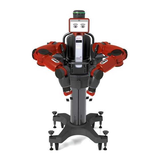
- Page 2 Thank you for purchasing Baxter, the world's first collaborative robot for manufacturing. This user guide is designed to provide you with an overview of the robot's features, help support you through the setup process, instruct you on training Baxter for tasks, and outline some basic troubleshooting measures should you need them.
-
Page 3: Table Of Contents
Setting Up Baxter 12 Accessories 12 Hardware 13 Front View 13 Back View 14 Grippers 14 How to Interact with Baxter 17 Using the Training Cuffs 17 Navigating the Screens 18 Moving the Arms 19 Grasping Objects 20 How Baxter Communicates 21... - Page 4 How to Make Detailed Modifications to an Action (Advanced Settings Screen) 71 Running Tasks 74 Create a Path for Baxter 75 Paths, Waypoints, Poses 75 How to Create a Custom Path for Baxter 76 Best Practices: Creating Waypoints 78 How to Practice a Path 78 How to Modify a Waypoint 80...
- Page 5 Maintaining Baxter 136 Cleaning Baxter 136 Replacing the Air Filters 136 Upgrading Software 137 Supporting Baxter 137 Helping Baxter When It Is Confused 137 Calibrating the Arms 138 Troubleshooting Baxter 141 Exporting Log Files 142 Enjoy! 142 Appendix A: Configuring Grippers 143...
- Page 6 Appendix B: Specify Object and Custom Gripper Weights 148 How to Specify Object Weight Appendix C: Configuring External Devices 151 Connecting a Modbus Remote Terminal Unit (RTU) to Baxter 153 Additional Information About the Modbus RTU 155 Appendix D: Signals and their Definitions 156...
- Page 7 Appendix G: Safety Mats 177 Appendix H: Support & Warranty 179 Contents Intera 3.2...
-
Page 8: Quick Start
Baxter’s arm may pull or miss Picks when performing tasks. Power On Baxter To turn Baxter on, press and release the white power button on the lower left back of the robot (See “Back View” on page 14 for the location.) Do not hold the power button down when powering on. -
Page 9: Move The Arm
Baxter’s wrist and grippers, and squeeze it just above the buttons on either side. Baxter is now in “Zero G” mode and you can now move the arm easily. Training Cuff (squeeze here) Release the training cuff and the arm becomes (semi-) rigid again. -
Page 10: Create A New Task
. A task can be very simple, like the pick and place you’re about to create, or much more complicated, involving both of Baxter’s arms moving in a coordinated fashion to and from multiple pick and place locations, holding a variety of poses, and sending and receiving signals from other machines and devices. - Page 11 You can both scroll the knob to move through options on Baxter’s display, or press it to make a selection. We refer to pressing the scroll knob to make a selection as “pressing the OK button” or sometimes, “press OK on the Navigator.”...
-
Page 12: Grasp An Object
For now you just need to know that the blue icon on the display represents Baxter’s right arm, the green icon represents the left arm, and the shaded area is where the arms can reach. Squeeze the training cuff and move one of Baxter’s arms. Watch as the appropriate icon moves on screen in response to the movement of the arm. - Page 13 Sub-tasks, and Actions” on page 28.) Still squeezing the training cuff, move the arm to the location where you want Baxter to place the object, then press the Grasp button again to release the object. Baxter nods and releases the object.
-
Page 14: Getting To Know Baxter
To set up Baxter: • Locate the installation card that ships with the robot. Follow the instructions to assemble the pedestal (if ordered), and attach Baxter to the pedestal or alternate work surface. • Follow the instructions included with the gripper kit to install a gripper. -
Page 15: Hardware
2. Attention ring 3. Display 4. Torso 5. Navigator (one on each forearm) 6. Lower front panel 7. Training cuff (shown with parallel gripper) 8. Training cuff (shown with vacuum gripper 9. Pedestal (optional) Getting to Know Baxter Intera 3.2... -
Page 16: Back View
5. Power and I/O panel (with DB15, USB, and Ethernet Ports) 6. Pedestal (optional) Grippers Grippers are the robot’s hands—they enable Baxter to grasp and release objects. The grippers wrist plate attach to the at the base of the robot’s training cuff. Baxter supports two standard Rethink Robotics grippers: electric parallel and vacuum cup, and can support some custom grippers. - Page 17 ELECTRIC PARALLEL GRIPPER 1. Training cuff 2. Gripper body 3. Fingers 4. Finger positions Getting to Know Baxter Intera 3.2...
- Page 18 VACUUM CUP GRIPPER 1. Training cuff 2. Gripper body 3. Pneumatic tube fitting 4. Vacuum cup Getting to Know Baxter Intera 3.2...
-
Page 19: How To Interact With Baxter
How to Interact with Baxter Using the Training Cuffs training cuffs Use the to move the arms, to manipulate the state of the grippers, and secondarily, to select on-screen options. 1. Training cuff switch 2. Grasp button 3. Action button Training cuff switch: Squeeze this switch at the indentation in the cuff to move the robot’s arm. -
Page 20: Navigating The Screens
Rethink button: Press to display options for the current screen. Training cuff indicator: When the switch on the cuff is squeezed, the blue indicators along the top and bottom edge of the navigator light up. Getting to Know Baxter Intera 3.2... -
Page 21: Moving The Arms
Squeezing the cuff releases the tension and resistance in the arm, making it easier to manipulate. With its seven degrees of freedom—an incredible amount of flexibility—Baxter enhances arm stability by attempting to fix its elbow in position whenever the lower arm is moved. -
Page 22: Grasping Objects
This will reset the elbow at the new position. Grasping Objects Training involves showing Baxter how to pick up and place objects. To grasp an object: Position the gripper over the object, press Grasp. -
Page 23: How Baxter Communicates
Baxter communicates through a combination of eye expressions, light rings, and thought bubbles. Baxter also responds to touch on a navigator or a training cuff—it stops moving and turns its head in the direction of contact on any of its primary touch points. -
Page 24: Attention Ring
The surprised expression is emphasized with an orange background when Baxter is working and unexpectedly detects someone has entered its space (currently, this only happens when a safety mat is connected and stepped on); Baxter also automatically slows its movement. -
Page 25: Condition Ring
Condition ring Light Color and Pattern What it Means Solid green Baxter is running a task Baxter is either idle or being Slow pulsing green trained by a user Baxter is confused and needs Solid yellow user assistance Baxter is in sleep mode;... -
Page 26: Confused Face Messages
Confused Face Messages When Baxter becomes confused, the display offers a list of possible explanations and solutions. “Light Bulb” Tips When you see a "light bulb" symbol on a screen, that means there is a tip (or tips) on how to use that functionality. -
Page 27: Main Screen
• Power – open Baxter power options: Sleep, Restart, Shutdown, Lock/Unlock. 4. Baxter eyes – Baxter uses eye expressions to communicate its current state. To navigate a button bar: Rotate the knob to scroll (referred to as “scrolling”) through options. When the option is highlighted, press the knob (OK) to select it. -
Page 28: Turning On Baxter
Press the white power button on the lower left back of the robot (see “Back View” on page 14 for the location). The lights on the head turn on, and the main screen appears on the Baxter display. Never hold the power button down to shut down Baxter. -
Page 29: Training And Managing Tasks
• Pose - A position and orientation of Baxter’s arm at a location. • Action Control - The parameter to tell the robot when the gripper should actuate. • Motion Preset - The parameter that defines how precisely Baxter’s arm follows a path’s waypoints. -
Page 30: Tasks, Sub-Tasks, And Actions
• Adding count – Baxter picks or places a fixed number of objects. (For Hold actions, you can change time instead of count.) • Adding signals – Baxter sends or waits for a signal before or after performing the action. -
Page 31: The Difference Between Vertical And Non-Vertical Tasks
(See “How to Make Detailed Modifications to an Action (Advanced Settings Screen)” on page 71.) If you train multiple sub-tasks per arm, you can order them in the sequence you want Baxter to perform them. - Page 32 The gray, overlapping shapes—called the —represent the maximum mechanical reach of each of the Baxter arms if the arms are fully extended and parallel to the shoulder joint. Baxter can execute actions within this area. The overlapping darker area towards the center of the workspace indicates the area shared between both arms, enabling the arms to operate within the same workspace.
- Page 33 THE TASK MAP LABELS 1. Baxter workspace 2. Right arm Place action 3. Right hand location 4. Right arm Pick action 5. Left arm Place action 6. Task name 7. Left hand location 8. Left arm Pick action Training and Managing Tasks...
- Page 34 • Run – Begin or continue the current task. • Order – Open the task order screen. • Rename – Modify the name of the task. On New, Baxter gives tasks a default name with a numeric suffix. Tip: Entering a unique, descriptive name will help you to more easily identify the task in the task gallery.
-
Page 35: Task Gallery
Task Gallery The Task Gallery is accessible from the main screen, when you select the Tasks button from the button bar. Use the task gallery to view the details of and select, copy, delete a trained task. You can also delete all the tasks on the robot from here. 1. - Page 36 • New – Create a new, empty task and open the task map. To delete all the tasks on the robot, press the Rethink button from the task gallery. Baxter displays buttons that allow you to create a new task or delete all the tasks on the robot. You will be asked to confirm deleting all the tasks.
-
Page 37: Training A Pick And Place
If Baxter’s wrist is not pointing straight down when performing an action, meaning the action is not vertical, a red circle is displayed next to the blue (for Baxter’s right arm) or green (for Baxter’s left arm) pointer. Non-vertical Picks cannot use vision. If the pointer is not blue or green but gray, Baxter cannot create an action in that location/pose. -
Page 38: Training A Pick Using Vision
Map and select the Pick. It will now be a vertical Pick. In some situations you will need Baxter to visually search for and recognize an object before picking it. Train a Pick using vision when: • You want Baxter to locate an object that varies in location and/or orientation by more than 0.2 inches (0.5 cm) each time. - Page 39 • Shadows in the work area, including those created by the object, degrade Baxter’s ability to see an object. So does glare, from the object or the work surface. • In general, the higher the contrast between the object and the work surface, the better.
- Page 40 5. Select the Train button on the object learning screen and press OK. Baxter moves to the Pick location, briefly grabs the object to line it up with its camera, then takes a series of pictures of the object from several heights. A series of images of the object are displayed in order from closest to furthest view.
- Page 41 Generally, Baxter will be able to recognize the object if the yellow overlay completely outlines the object. 6. If Baxter cannot recognize the object, first try again, keeping in mind the troubleshooting tips (See “Troubleshooting tips:” on page 44) You can also adjust the camera settings (See “Camera Settings”...
- Page 42 8. From the vision screen, press OK to select the picture that best represents the shape of the object, then press the Next button. Baxter takes more pictures of the object from various locations to gather more data and refine its perception of the object.
- Page 43 When done, Baxter displays a live view of the object on the Test and Select Model screen. Training and Managing Tasks Intera 3.2...
- Page 44 • The blue outline identifies Baxter’s understanding of where the object is. • The yellow circle represents Baxter’s view of the center point of the axes of the object. • The red arrow illustrates how Baxter perceives the orientation of the object for gripping.
- Page 45 On the left side of the screen, Baxter flags the recommended model of the object with a star symbol. Other possible models are also displayed. In general you will want to use Baxter’s recom- mended model, but advanced users, or users looking for a particular type of model by which to rec- ognize the object in question, may want to select from the list.
- Page 46 9. Select the best model. The object is now trained. TROUBLESHOOTING TIPS: If Baxter did not locate the object, or if the object is not correctly covered by the overlay, try the fol- lowing: • Adjust the lighting in the work area to improve the contrast and remove shadows around the object.
-
Page 47: Camera Settings
Camera Settings You can change the settings for Baxter’s cameras to adjust for the amount and quality of light Bax- ter perceives in the work area. (Technical note: the adjustments apply primarily to the lighting vari- ables of gain, white balance, and exposure.) You can make adjustments using a simple slider or you can let Baxter adjust its own camera lighting settings automatically by selecting the Auto checkbox. - Page 48 1. Select the More Options icon 2. Select the camera settings button Baxter displays a live camera view. Training and Managing Tasks Intera 3.2...
- Page 49 There is a slider underneath a live camera image of the active camera’s arm. You can scroll among the slider, the “Auto” option, the Back button, and the Done button. (If “Auto” is active, the slider is not needed, therefore it’s not highlighted.) 1.
- Page 50 (This is also known as decreasing or increasing the gain, respectively.) If you have trained an object using vision, you can see in real time the effect your lighting adjust- ments have on the object and on Baxter’s detector (the blue outline/yellow circle/red arrow indicators).
-
Page 51: Training A Group Of Pick Or Place Actions
Training a Group of Pick or Place Actions When you need Baxter to pick a group of objects from a number of individual locations, or place them in a number of individual locations (e.g., when moving items from or into a segregated box or... - Page 52 5. When finished, press the Back button. (Don’t press OK to finish. That will continue to add locations to the action group.) NOTE: If, when training Baxter, you need to put an object in the gripper and you don’t want to copy double-click or add a new action, the grasp button.
-
Page 53: Managing Tasks And Sub-Tasks
Managing Tasks and Sub-tasks Use the Task Order Screen to display and change the order of actions that make up a task. You can also use this screen to manage task settings and add counts or signals to a whole task or part of a task known as a sub-task Use the Task Order screen to view the current sub-task order, rearrange and combine sub-tasks,... -
Page 54: Task Button Bar
• Signals – Add a signal to a sub-task, or remove one. (See “Signals” on page 127.) • Motion Presets - Define how Baxter's arm follows a path's waypoints. These presets will help Baxter complete a wider variety of tasks. (See “Motion Presets”... -
Page 55: Sub-Task Button Bar
Sub-task Button Bar Top row, left to right: • Back – Close the button bar and return focus to the task order screen. • Count – Add count to a sub-task. • Copy – Copy a sub-task and all its details to the same location on the Task Map. The copied sub-task will appear on the Task Map just below the original. -
Page 56: Coordinating Sub-Tasks Across Arms
You can also modify or delete sub-task names. Coordinating Sub-tasks Across Arms Coordinating arms allows Baxter to conduct a sub-task on one arm before conducting a sub-task on the other arm. 1. Pick the sub-task you want to move relative to the other arm. Press OK. - Page 57 3. Scroll to the right or left to move the yellow line until it appears after the sub-task that the selected sub-task should follow. 4. Press OK. After the sub-tasks are coordinated, a gray line appears between them to indicate the order. Training and Managing Tasks Intera 3.2...
-
Page 58: Combining Sub-Tasks
Baxter will determine in which order to complete the sub- tasks. Baxter will combine two sub-tasks next to each other on the same arm. - Page 59 3. Select the task bar at the top of the screen, and press OK. 4. Click the More Options icon. 5. Click the End Effector Settings icon. Change the setting. Training and Managing Tasks Intera 3.2...
- Page 60 Examples: For a single piece of paper, which is likely porous, set a lower threshold. • That tells Baxter the material is porous and the gripper sensor will trigger at a lower threshold. Training and Managing Tasks Intera 3.2...
-
Page 61: Change Number Of Attempts To Pick An Object
Change Number of Attempts to Pick an Object Baxter attempts to pick up a specific object by default twice. (If it misses the first time, it will try again, and if misses a second time, Baxter will stop.) You can change this setting to be any number between 1 and 99. - Page 62 1. With the task highlighted on the Task Order screen, select the advanced settings icon. 2. Scroll to Attempts on the resulting menu and select it. Training and Managing Tasks Intera 3.2...
- Page 63 4. Change the number of attempts to your preferred number. (A check box also gives you the option of stopping Baxter immediately if the object is dropped.) 5. Press the Return button on the Navigator to make the change for that task.
-
Page 64: Modifying Actions
Modifying Actions Modifying a Pick Action You will want to modify a Pick action if: • The surface (such as a conveyor belt) is moving. • The location will vary more than 0.2 in (0.5 cm). • The robot needs to identify a specific object. •... - Page 65 • Add Signal – Specify which defined signal(s) you want to attach. • Add Weight - Specify a weight for the object Baxter will hold for a task. • Add Landmark - Create a landmark used by the Robot Positioning System.
-
Page 66: Customizing The Size Of A Visual Search Area
Customizing the Size of a Visual Search Area By default, when vision is turned on, Baxter looks for objects within a small, limited area. To resize the area (such as to expand it to the width of a conveyor or to the size of a box), you can train a visual search area. -
Page 67: Modifying A Place Action
If you fail to return to the original point you taught, the area will be drawn as a triangle, which is probably not what you want. The smaller the search area you define, the faster Baxter is likely to perform the task. Modifying a Place Action You will want to modify a Place: •... - Page 68 10. – Practice or modify the approach, retract, or action poses. You can also change the distance Baxter’s arm travels as it approaches or retracts, and determine how slowly the arm should move when approaching or retracting. See “How to Modify/Practice an Action”...
- Page 69 To move a Place location: 1. On the modify screen, click Move. The task map opens with a temporary “ghost” copy of the location displayed with the move icon over it. 2. Move the arm to drag the ghost to the desired new location. Tip: Remember to maintain arm pose alignment.
-
Page 70: Modifying Count
Modifying Count Actions/action groups and tasks have the following counts by default: • Pick action – unlimited count • Place action – count of 1 • Action group (for both Pick and Place) – count of 1 for each location within the group. - Page 71 1. Select the action on the Task Map. 2. Scroll to the icon and press OK. Training and Managing Tasks Intera 3.2...
- Page 72 Baxter displays the modify screen. 3. Scroll to the Modify button and press it. Baxter displays the modify action screen. Training and Managing Tasks Intera 3.2...
-
Page 73: How To Make Detailed Modifications To An Action (Advanced Settings Screen)
Baxter’s arm and hand move to the point as you scroll to it. 5. Grab Baxter’s cuff, adjust the pose and/or location, and press the action button on the cuff. A check mark is briefly displayed on the screen to register the new pose/location. - Page 74 Retract Distance – The distance Baxter’s arm will travel when it retracts from an action, for example, a Place. (More technically, this is the point along a vector perpendicular to the position on the cuff joint from the action’s location that will move into position before moving along the vector to the...
- Page 75 Settings Screen to align the Approach, Action and Retract poses. Action Control Settings – Select here to control when Baxter will perform an action. The options are: • At Location – The robot will grip or release a part when it arrives at the trained position -- not when it feels force from an object or achieves a vacuum seal.
-
Page 76: Running Tasks
• Vacuum Gripper - At Location Drop Height – Define here the height above zero at which Baxter will perform a Place. For vertical Place actions only. (The zero point on Baxter is where the gray lower front panel meets the black metal that connects to Baxter’s pedestal.) -
Page 77: Create A Path For Baxter
Paths, Waypoints, Poses There are times when you may want to define the path Baxter’s arm takes when it moves from one action to another. This is useful for basic machine tending, for example, or to ensure the arm avoids path hitting items in the immediate work area. -
Page 78: How To Create A Custom Path For Baxter
A pose is a position and orientation of Baxter’s arm (shoulder, elbow, hand, wrist, etc.) at a way- point. default custom There are also two kinds of paths: A default path is one in which you allow Baxter to create waypoints along the path automatically. - Page 79 Cartesian Coordinates between the Pick or Place and the Approach and Retract points. This is important when Baxter needs to move along a straight line in the direction of the gripper, such as when placing an object into a box or assembling two components. However, while the transit way- Create a Path for Baxter Intera 3.2...
-
Page 80: Best Practices: Creating Waypoints
Approach and Retract points. • If, when training Baxter, you need to put an object in the gripper and you don’t want to create a new action, double-click the grasp button. - Page 81 2. Select the Path icon in the Modify widow and press OK on the Navigator. Baxter displays the Task Map with the action and its path. Create a Path for Baxter Intera 3.2...
-
Page 82: How To Modify A Waypoint
Baxter practices the path. Note: You can grab the cuff while Baxter is in practice mode to stop the arm from moving. That does not alter the waypoints in the path or any of the poses associated with the path. - Page 83 3. Press the Modify button. 4. Scroll the Navigator knob to the waypoint you want to modify. Each waypoint is highlighted with a halo as you scroll to it. Baxter’s arm will move through each waypoint until it reaches the selected waypoint.
-
Page 84: How To Modify A Path (Includes Practice And Retrain)
How to Modify a Path (includes Practice and Retrain) 1. With a task already created, select the action where the path originates. For example, if the path is from a Pick to a Place, scroll to the Pick. Create a Path for Baxter Intera 3.2... - Page 85 2. Press OK and select the Paths icon from the Modify screen. Baxter displays the Task Map. Create a Path for Baxter Intera 3.2...
- Page 86 3. From the Task Map, scroll through the possible paths, and press OK on the one you want to change. Baxter displays this screen. From here you can choose to practice, modify, or retrain the path. After making changes to a custom path you can quickly apply those changes to its return path by clicking the Apply to Return button.
- Page 87 (You can then add new waypoints to the path.) Retrain is also an option in the Modify Panel submenu for selected waypoints. MODIFY Modify enables you to change one point at a time, whether it’s an action, a transit point, an approach or retract. Select Modify. Create a Path for Baxter Intera 3.2...
- Page 88 Baxter displays the Modify Waypoints panel. 2. Select a waypoint by scrolling to it and pressing OK on the Navigator. The submenu changes depending on the kind of waypoint selected and the kind of action upon which the path is based.
- Page 89 To add a waypoint: 1. Select a path from the Task Map. 2. On the screen, select Modify. Baxter displays the Move Pose Mode screen. 3. Scroll to the waypoint on the path before which you want to insert the new pose/ point.
- Page 90 4. Press OK to display the submenu for that waypoint. 5. Select Add. Baxter displays the screen in Add Waypoints Mode. Create a Path for Baxter Intera 3.2...
-
Page 91: Motion Presets
NOTE: You may find that some locations or poses will be invalid. That means the location or pose cannot be performed by Baxter because it’s near a joint limit. On the Task Map this would show up as a grayed out icon. On the screen, Baxter displays the message, “Add pose failed.”... - Page 92 2. Press OK to display the menu button bar. 3. Select the Motion presets icon. The current or default motion preset is displayed. Create a Path for Baxter Intera 3.2...
-
Page 93: How To Change The Motion Preset At The Action Level
1. Highlight the pick, place, or hold action on the Task Map and press OK. 2. On the modify action screen, select the icon. 3. Select the Advanced icon on the modify screen to display the advanced action modification screen. Create a Path for Baxter Intera 3.2... - Page 94 The destination action -- the action to which the arm is moving along the path -- is where you apply the motion preset. For example, if you need Baxter's arm to move in a controlled, deliberate fashion from a Hold to a Pick, you would open the advanced screen for the Pick and choose Explicit.
-
Page 95: Hold
Hold Baxter can hold an arm in position for a defined period of time or an unlimited period of time until a signal is triggered. This feature is useful for such jobs as holding an object in a pose (or a series of poses) for inspection, scanning, labeling, painting, etc. -
Page 96: How To Modify A Hold
5. Select Hold and press OK. Baxter creates a Hold action and displays a Hold icon on the Task Map. (As with other actions, Holds display their numbers, which are based on the subtask.) Note that the Hold icon has a time feature indicator associated with it. The default Hold time is zero seconds. - Page 97 2. Select the Add Features button to display the Add Features submenu. This submenu allows you to add a signal to a Hold or modify the duration of a Hold. Hold Intera 3.2...
-
Page 98: How To Create A Series Of Hold Subtasks
The Unlimited Hold capability gives you greater flexibility when working with tasks that require sig- nals to move on from a Hold. Note: As of Intera 3.2, Baxter no longer displays a confused look if a ready signal is assigned to a Hold. How to Create a Series of Hold Subtasks 1. - Page 99 You can re-order a hold into a new subtask. Baxter treats hold-only tasks as if there is no object in hand, so you cannot specify a weight for a part. If Baxter's arm is holding a part that has some weight to it, the movement and performance of the arm can be unsteady.
- Page 100 Hold Intera 3.2...
-
Page 101: Nudge
(You cannot nudge a vertical action's approach and retract points.) How to Nudge a Pose 1. Select a pick, place, or hold action on the Task Map. Baxter displays the action's Modify panel. 2. Select the icon. The panel is displayed. - Page 102 The Back and Nudge buttons are displayed. 5. Select Nudge. Baxter moves its arm to the currently defined pose and displays the options for how the pose can be nudged. Nudge...
- Page 103 Training cuff profile: camera on right Training cuff profile: camera in back In short, when you nudge Baxter's cuff, make sure the profile of the robot matches the image shown in the display. YAW, PITCH, AND ROLL Yaw, pitch, and roll are terms used to describe the way in which an airplane moves about its three axes.
- Page 104 It is helpful to keep these terms in mind when using the bottom row options (on the next page) in Nudge. Just picture the orientation of Baxter’s wrist as below and equate this orientation with the nose of an airplane. In other words, picture the front view of wrist, with the gripper fingers pointed at and the camera on the bottom , as being the nose of the airplane.
- Page 105 Pitch Roll (Top row) You can nudge the arm in millimeter increments along the X, Y, Z axes of the cuff (called a translation change) specifically: • along the x axis: in a line from the gripper connector to cuff camera •...
- Page 106 Navigator scroll knob. You can nudge at intervals of 1 mm for translation and .25 degrees for orientation. Baxter's arm moves to the new location or angle. This option will nudge the arm -8mm along the x axis from its present pose.
- Page 107 (along the z axis) from Baxter. 7. To save the new pose, press OK. Note: You can make multiple nudges to Baxter's arm, both along and around the XYZ axes, by pressing OK after each Nudge. 8. When done, press the Save button.
- Page 108 • You cannot nudge transit waypoints. You can use the Navigator on either arm when in Nudge mode. Nudge Intera 3.2...
-
Page 109: Lock/Unlock
This feature requires a USB device, formatted FAT32, with a text file with the name, RethinkPass- word.txt. Baxter will recognize this .txt file only if it resides on the USB device's root directory. You can create your own text file with this character string or download it directly from the Rethink Robotics FTP site. - Page 110 2. Once the stick is inserted, from Baxter's button bar, select Sleep. 3. Select Lock or Unlock, depending on what state you want Baxter to be in. Lock/Unlock Intera 3.2...
-
Page 111: Robot Positioning System
Robot Positioning System Introduction Collaborative robots are designed to work next to humans and to be deployed quickly from one task or work cell to another. This design is a beneficial one but it also introduces a whole new set of challenges for robotics. -
Page 112: When To Use The Robot Positioning System
These landmarks are placed on the surface of modules in the work area. If Baxter -- or the surface containing the landmark on which an action takes place -- moves, either accidentally or not, you can use the Robot Positioning System feature to re-register the action in relation to the original location and quickly reorient Baxter in relation to the task. -
Page 113: How To Create A Landmark
We recommend landmarks be no further than 50 cm away from the actions associated with them. • To allow Baxter's imaging system to see the landmark, position the end effector camera approximately 20cm above the landmark, with the landmark in the center of the field of vision. - Page 114 Baxter should recognize the landmark and highlight it with a green outline. If Baxter cannot locate the landmark, as in the example below, do one of the following: • make sure the camera is 20cm above the landmark.
- Page 115 The strength of the recognition is displayed by the height and brightness of the vertical green bar in the middle of the screen: taller and brighter = stronger recognition. The landmark is recognized when it is outlined in green and a message displays with the landmark's number, as in the example below.
- Page 116 3. Save the landmark by selecting Save, but, to avoid moving the camera, press the OK button on the torso or the other arm. When the landmark is saved, the screen displays a checkmark and the number of the landmark, as in the example below.
-
Page 117: Alternate Way To Create A Landmark
Alternate Way to Create a Landmark You can also create a landmark this way: 1. Press the Rethink button. 2. Select the landmark gallery icon. Robot Positioning System Intera 3.2... - Page 118 3. Select Create New. Robot Positioning System Intera 3.2...
-
Page 119: How To Associate A Landmark To An Action
That displays the Create a Landmark screen, as seen previously. 4. Save the landmark as before, using the navigator button on the torso or other arm. How to Associate a Landmark to an Action 1. Select the action on the Task Map. 2. -
Page 120: How To Reregister A Landmark
After one or more of the action locations has been moved -- whether because the robot has been moved, a fixture has been inadvertently bumped, Baxter has been inadvertently bumped, etc. -- it's easy to reregister the actions using the Robot Positioning System rather than retrain them. - Page 121 Note: When re-registering to a previously associated landmark, it's very important that you do not move the arm from the original location. Doing this will introduce error into the associated actions. To reregister a landmark: 1. Press the Rethink button. 2.
- Page 122 If the new location of the landmark is no more than 50mm and/or 10 degrees rotation from the orig- inal landmark location, Baxter will recognize the new location. If the new location is too far off, just move Baxter or the module until the green outline is displayed. 6. Press Reregister.
- Page 123 The landmark is reregistered (note the checkmark) and the location is realigned with the original task location. Robot Positioning System Intera 3.2...
-
Page 124: Robot Positioning System - Best Practices
• The weight of the grippers can affect the accuracy of Baxter's arm movements. If you register landmarks for a task with the grippers attached, make sure the grippers are also attached when you reregister. -
Page 125: Frequently Asked Questions About Robot Positioning System
Q: Does the landmark need to be trained at the same orientation as the pick or place action? A: No. You could have your landmark mounted horizontally to the frame of the conveyor even though Baxter will pick in an off-vertical orientation on the conveyor. Q: Can a landmark be associated with a Hold? Robot Positioning System Intera 3.2... -
Page 126: Application Examples
TASK DESCRIPTION Baxter is working on a rotary table offloading parts from the table and placing them on conveyors to either side of the robot using both arms. The rotary table has more than one nest where it will pick parts from. -
Page 127: Transferring Parts From One Conveyor To Another
Transferring Parts from One Conveyor to Another TASK DESCRIPTION Baxter is working at the end of a line transferring parts from one conveyor to another and is using both arms. Operators work near the conveyors and often bump into these, moving them out of place and Baxter has problems picking or placing. - Page 128 1. Train PICK and PLACE. 2. Position one landmark on the fixture close to the actions. 3. Train each ACTION to its relevant landmark. Done. Robot Positioning System Intera 3.2...
-
Page 129: Signals
• In Ready (level and edge) – Signals to Baxter that the external world is ready for it to perform an action. In some cases, the In Ready signal also tells Baxter to reset counts. - Page 130 • In Do Subtask - Allows you to more easily tell Baxter what to do and when to do it. If a task has all its subtasks with the Do Subtask signal assigned, each subtask is, in effect, in "listening"...
-
Page 131: Internal Signals
5 seconds or as little as .5 seconds. The default is 1 second. • Reset Out - Baxter can send a Reset Out Signal to reset a PLC when the user presses “Reset” in Baxter’s UI. Returns all counts to 0. - Page 132 THE SIGNALS GALLERY From the Task Map, press the Rethink button, and click I/O to access the signals gallery . Use this screen to view available signals, or add new ones. When you first access the signals gallery, it will be blank, as in the illustration above, if no signals have been created yet.
- Page 133 1. Create signal – Add a signal to the gallery. 2. Displays a list of all signals defined for the current task. 3. Displays the details of the selected signal. • Name of the signal • Device name and line number •...
-
Page 134: Creating Signals
Creating Signals To set up signals, first attach and configure the device (see “Appendix C: Configuring External Devices” on page 151), then, create a signal and store it in the signal gallery: 1. In the task gallery, click the create signal icon. 2. -
Page 135: Assigning Signals
4. Select the plus (+) button to define a signal and its attributes. 5. When finished, click the Back icon on the screen. SIGNALS NOTES • You can easily invert the signals Baxter sends or receives by clicking on the invert signal icon in the Polarity column. - Page 136 READY SIGNAL: CONFIGURE AS GATE OR ENABLE For pick and place actions with a Ready signal, you have the option of instructing Baxter what to do if a signal that was true when Baxter started the action becomes false. For example, in the case of using a part present signal, if the part disappears (and the signal is false), you can choose whether you want Baxter to continue moving or to stop.
- Page 137 • If Gate is chosen for the signal, (the gate being defined as the action’s approach), once past the gate, even if the part present signal disappears, the arm will continue. Signals Intera 3.2...
-
Page 138: Maintaining And Supporting Baxter
To clean Baxter, periodically wipe it down with a clean, damp cloth. Replacing the Air Filters Check the Baxter air filters at least every six months, and replace them as necessary. Baxter has two air filters, one on each side of the torso. -
Page 139: Upgrading Software
Typically you will be able to solve the problem yourself. In some cases, however, you may need to contact your technical support representative for assistance. Helping Baxter When It Is Confused When Baxter encounters a problem, it typically will stop and display a message on the screen. Maintaining and Supporting Baxter Intera 3.2... -
Page 140: Calibrating The Arms
Other types of “confused” screens concern external devices not being connected, internal signals not being fully defined, and end effectors that are not configured. If the issue is not solved even after shutting down and restarting Baxter, contact your technical support representative for assistance. - Page 141 5-foot radius. If one (or both) of the Baxter arms begins to lose pick and place accuracy while performing trained tasks, try calibrating the arm(s) to fix the problem. Baxter offers three types of arm calibration: •...
- Page 142 To calibrate an arm: 1. Make sure there is a clear, 5-foot radius around and above the base of the robot. If Baxter is attached to a pedestal, and it is not possible to clear the workspace around the robot: •...
-
Page 143: Troubleshooting Baxter
9. Restart the robot. 10. If the grippers were removed and reinstalled, configure and train each gripper. If after calibration, Baxter still does not function correctly, try retraining and running the task. If the problem is not solved, contact your technical support representative. -
Page 144: Exporting Log Files
On behalf of the entire team at Rethink Robotics, we wish you great success with your Baxter robot, and hope you find it to be a valuable solution for your business. Several appendices follow, with more detailed examples of information contained in this document. -
Page 145: Appendix A: Configuring Grippers
Appendix A: Configuring Grippers When you attach a Rethink gripper, Baxter automatically detects the gripper type, and prompts you to configure it. Configuration teaches Baxter: • Finger type and open/closed finger position of a parallel gripper • Vacuum cup size of a vacuum gripper You can also attach custom or third party grippers the same as Rethink grippers, essentially by entering the gripper’s length and weight and then training Baxter. -
Page 146: Configuring A Vacuum Cup Gripper
Configure End Effectors. 3. If you need to install or adjust the gripper, depending on where you are standing, click Behind or Front. Baxter automatically presents its hand to you, either in front, or off to the side in back. - Page 147 Click Done, then select the vacuum cup’s Weight icon. 6. Enter the weight of the gripper and click Done. 7. Click Train. The gripper rotates as Baxter learns it. Intera 3.2...
-
Page 148: Configuring An Electric Parallel Gripper
Behind or Front. Baxter automatically presents its hand to you, either in front, or off to the side in back. Note: You can also manually move the arm to access the gripper. Here are the weights and lengths for each component in the Baxter gripper kits: Component Weight (Kilograms) Length (Millimeters) Electric Parallel Gripper without 0.3 Kg... -
Page 149: Configuring A Non-Actuating Custom Gripper
You can also attach a non-actuating custom gripper to Baxter for use with hold subtasks, for exam- ple, for tasks using a vision system. The camera is attached to the end of Baxter's arm but not plugged in to the robot’s wrist. You must still configure and train a gripper even if you are not using a gripper or a non-actuating gripper in your hold subtask. -
Page 150: Appendix B: Specify Object And Custom Gripper Weights
Baxter’s arm performance will likely suffer.) Baxter can support up to five pounds (2.2 kg) on each of its end arms. An end effector is made up of the plate and its attachments (electronic gripper or vacuum, fingers). - Page 151 2. Scroll to the Add Features button and press OK to display the task button bar. 3. Highlight the Weight icon and press OK to display the weight entry screen. Intera 3.2...
- Page 152 4. Select the spin box, enter the desired weight and press OK. 5. Press Done to confirm the weight. 6. Press the Back button on the Navigator once to return to the Task Modify screen. The weight appears in the Modify window with its own Added Features button. 7.
-
Page 153: Appendix C: Configuring External Devices
Note: For the latest information, please refer to our wiki at: mfg.rethinkrobotics.com Baxter communicates to external machines via its open logic ports in one integrated DB15 connec- tor or by adding an external Ethernet-connected Modbus Remote Terminal Unit (RTU). Attach a terminal block to the DB15 connector to accommodate two signal lines—one in and one out—and provide lines for the e-stop and a safety mat. - Page 154 Pin 4: Torso 0 In (Ready In), 5v – 24v Pin 12: Torso 0 In Return (Ready In Return) Pin 7: Torso 0 Out (Done Out), +5v – +24v MUST BE EXTERNALLY CURRENT LIMITED, 10ma MAX Pin 15: Torso 0 Out Return (Done Out Return), Note: • Torso 0 In is FALSE when current is flowing, and TRUE otherwise. A disconnected input will appear as TRUE. • Torso 0 Out is open when FALSE, and closed (current flowing) when TRUE. Intera 3.2...
-
Page 155: Connecting A Modbus Remote Terminal Unit (Rtu) To Baxter
With Baxter 1.1 software, Rethink Robotics qualified the Moxa ioLogik E1212 Note: Remote Terminal Unit. 2. With Baxter shut down and powered off, attach the device to the Ethernet port. 3. Turn on the device. 4. Power Baxter on. 5. Go to Settings > Hardware Settings > Configure Modbus. - Page 156 6. In the device list screen, select the icon to add a device. 7. In the configure new device screen, enter the following: • Device Name – Keep the default, or enter a descriptive name for the device (maximum 16 characters). Tip: Create an easily recognizable name.
-
Page 157: Additional Information About The Modbus Rtu
• The ModBus device must be configured in SLAVE mode. When using settings other than the default, you must set the input and output base addresses in the Baxter configuration panel if other than 0/0, and the inputs and outputs must be digital (discrete coils, not registers) and contiguous. -
Page 158: Appendix D: Signals And Their Definitions
Appendix D: Signals and their Definitions This appendix discusses available signals and their exact definitions. Terminology Signal: a signal transmits a piece of information. Signals are binary, meaning they are only on or off. A signal can be an input signal received by Intera from an external source or an output signal sent by Intera to an external source. -
Page 159: Signal Types
Pulse (output), edge (input): the information is contained in the change of the signal from false to true (the rising edge of the signal.) How long the signal remains true doesn’t matter. This represents the occurrence of an event. For example, when an action is started, a pulse is sent. - Page 160 Task Reset In (edge and level): pauses (level) and resets (edge) the task. Error In (level): stops the task. Pause (level, enable): pauses the task when asserted Do Subtask (level): when true, signal the subject is allowed to run. Reset Count (edge): reset count for the associated task element. OUTPUTS Done (level): the count for the particular task element has been reached.
-
Page 161: Task Element Details
would allow the task to proceed or whether the rising edge of Ready will reset a count or error state. If so, Intera suppresses the confusion signal. Task Element Details ACTION An action is a Pick, Place or Hold that is performed at a particular pose in the workspace. Signals can be attached to a single Action that is not part of an Action Group. -
Page 162: Signals
SUBTASK A Subtask comprises one or more Action Sequences. Subtasks are defined to end when no Action Sequence is running and either: a. all of the Place counts for all Actions in all Action Sequences in the Subtask are full or, b. - Page 163 Error In (level): when true, the robot is stopped. The user will need to press the • run or reset button. The Error In signal can be asserted at any point in task exe- cution, or even during training. •The Error In signal can be assigned to the task for each arm, but asserting the signal on either task will stop both arms.
-
Page 164: Subtask
•In a non-coordinated task, it is possible for one arm’s task to be paused due to confusion while the other arm’s task continues to run. • Reset (pulse): signals pulses true when the task is reset by any means. SUBTASK INPUTS •... - Page 165 •If Ready goes false while an action is running and the action has not yet taken place (i.e., the part has not yet been picked or placed), then the action is aborted immediately. If the action has been performed then it completes normally regardless of the state of Ready.
-
Page 166: Other Actions: Hold
OTHER ACTIONS: HOLD INPUTS • Ready (level (enable)): when false, prevents the action from running. When true, allows the action to run if all other conditions are met (e.g., count.) •If Ready goes false before the hold time is up, then the Hold is aborted immediately and the Action Sequence will wait until Ready becomes true before restarting the Hold. - Page 167 Subtask ends, whereas Subtask counts are reset when the Task completes. Due to the automatic resetting (e.g., in a Subtask with only one Place Action, the Subtask will end when the count is sat- isfied and then immediately reset the count). Done signals may only stay true for a short period of time, but in any case no less than 0.5 seconds.
- Page 168 b. To run a particular Subtask, the PLC should set that Subtask’s Skip signal to false. To operate reliably, the signal should remain false until the PLC receives a positive acknowledgment that the Subtask has started. This could be from the Start signal of the first Action, for example. c.
- Page 169 Intera by asserting only one signal representing the required action. Q: Where can I get the most up-to-date information on signals, Intera 3.1, or anything else related to Baxter? Please visit our Wiki at: mfg.rethinkrobotics.com...
-
Page 170: Appendix E: Transfer Tasks From One Baxter To Another
How to Export Tasks from a Robot 1. Insert a USB device, formatted as FAT32, into the USB port on Baxter. 2. On Baxter, go to 3. Main Screen > Settings > Advanced > Export/Import Tasks. - Page 171 5. Press OK. Baxter displays its tasks. All tasks are selected by default. 6. To select just some of the tasks, scroll to each particular task and select it or deselect it by pressing OK when it is highlighted. Intera 3.2...
-
Page 172: How To Import Tasks To A Robot
Because the physical world of the two Baxters – the Baxter from which the task was imported and the Baxter to which the copied task was exported – are not identical, you may need to refine these tasks. Here is a checklist of troubleshooting situations you may encounter: •... - Page 173 • The task runs but the workspace is different from the original in some way. In this case, the operator has to tweak the layout of the workspace or the paths of Baxter’s arms. • The lighting is different. That could affect Baxter’s vision. See “How to Change the Lighting Settings for Baxter’s Cameras.” Intera 3.2...
-
Page 174: Appendix F: Tips & Best Practices
The camera does not operate for non-vertical tasks. Workspace and Robot Joint Limits The ability of Baxter to perform actions at any given location is affected by the physical limits of the arms. When training an action, consider: • Each of the robot’s joints has limits. The closer you are to the edge of these limits, the greater the chance the robot will be unable to train an action. -
Page 175: Waypoint Wisdom: Tips For Creating Custom Paths
Keep this in mind when planning your approach and retract points. • As of Baxter software 2.1, it is no longer necessary -- or even desirable -- to define a large number of waypoints when training a path. The more transit points you add, the longer the path and therefore, the more time the task will take. - Page 176 The illustration below (not to scale) shows the Finger Selection and Position Guide included in the inside cover of the Parallel Gripper Kit . Key concepts to remember when choosing fingers and position are: 1. Place the object in the center of the chart in the same orientation as the robot will grasp it.
-
Page 177: Object Training And Visual Search
• Aim to have high contrast between an object and the surface. • Baxter cannot learn an object if it is moving during training. • See “Training a Pick Using Vision” on page 36 and “Camera Settings” on page 45 for more details about how to effectively train Baxter using vision. -
Page 178: Stacks
o If the location of the object is randomly located anywhere on the conveyor belt, trace an area that is the full width of the conveyor. Stacks • When training a stack above the waist, train the bottommost object in the stack and use Contact or First as the Action Control. - Page 179 Baxter supports the optional use of a safety mat—a 4-wire Normally Open (N.O) configured mat of any size or shape (user-supplied, not included. To connect a safety mat to Baxter, use a terminal block that can connect to the DB15 connector on the I/O panel on the back of the robot’s waist, and support a male-configured DB15 connector for the e-stop button.
- Page 180 Note: Unless shown as a jumper in the above diagram, all other wiring is pin-for-pin on each connector. Intera 3.2...
- Page 181 These can be found on the back of the robot near the power button. If the product is no longer within the warranty period, the authorized Rethink Robotics service provider will provide an estimate of the technical support or repair costs.
- Page 183 Last updated April 17, 2015 P/N 26004 – Rev C...
Need help?
Do you have a question about the Baxter and is the answer not in the manual?
Questions and answers