Siemens Pointek CLS 200 Instruction Manual
Versatile capacitance switch with a high level of chemical resistance
Hide thumbs
Also See for Pointek CLS 200:
- Quick start manual (200 pages) ,
- Operating instructions manual (150 pages) ,
- Application examples (8 pages)
Table of Contents
Advertisement
Advertisement
Table of Contents

Related Manuals for Siemens Pointek CLS 200


Summary of Contents for Siemens Pointek CLS 200
- Page 1 Instruction Manual July 2004 pointek CLS 200...
- Page 2 DELLSONICS 北京迪妙声科技有限公司 BEJING DELLSONICS SCIENCE & TECHNOLOGY LTD. 公 司 简 介 北京迪妙声科技有限公司(原名北京妙声力科技有限公司) ,位于北京市海淀区中关村 南大街,是与西门子公司德国总部正式签约的西门子过程仪表及分析仪器核心合作伙伴, 也是西门子北方区域规模最大、实力最强的优秀代理商。 公司主营: 一、 西门子-妙声力(Milltronics)系列物位产品:超声波物位计、超声波液位差计、超声波泥水界 面计、超声波明渠流量计、雷达物位计、射频导纳物位计、射频导纳油水界面计、 ;射频导纳物位开关、 音叉式物位开关、阻旋式物位开关;皮带称、固体质量流量计、冲板流量计等。 二、 西门子过程仪表产品:电磁流量计、质量流量计、超声波流量计、 温度变送器、压力变送器、 阀门定位器、气体分析仪等。 三、 德国 UWT 公司的阻旋式料位开关、音叉式料位开关、重锤式料位计等产品。 四、 自行研发生产超声波液位计、温度变送器、压力变送器、数显表及油田专用仪器等产品。 成立于 1954 年的西门子-妙声力公司 是世界公认的超声波物位测量领域 (Milltronics) 的领导者, 全球最大的超声波物位仪表生产厂家, 在超声波、 雷达、 电容技术领域拥有超过 60 项专利,超声波产品的综合性能指标经美国《控制》杂志评比,其综合性能名列全球第一!...
- Page 3 Safety marking symbols ......................1 The Manual ............................2 Application Examples .........................2 Abbreviations and Identifications ...................3 Part I: Pointek CLS 200 analog model ......... 5 Pointek CLS 200 analog model .................6 Pointek CLS 200 Applications .......................7 Pointek CLS 200 Features ......................7 Specifications: analog model ...................8 Pointek CLS 200 ..........................
- Page 4 Part II: Pointek CLS 200 digital model ....... 27 IIA: information common to any digital unit ................27 IIB: standalone unit ........................27 IIC: unit on a PROFIBUS PA network ...................27 Pointek CLS 200 digital model ................28 Pointek CLS 200 Applications .....................29 Features ............................29...
- Page 5 Wiring: connection to a PROFIBUS PA network ..........60 Electrical Connection ........................60 PROFIBUS PA connection to screw terminals ..............61 PROFIBUS PA connection via M12 plug ................62 Communications via PROFIBUS PA: Pointek CLS 200 digital model ....63 SIMATIC PDM ..........................63 Device Description ........................63 Configuration ..........................64 Setting the PROFIBUS address .....................64...
- Page 6 Product Nameplate: Pointek CLS 200 ..................104 Product Nameplate: Pointek CLS 200 (continued) ..............105 KEMA certificates and schedules ..................106 KEMA amendment ........................113 Appendix E: Installation, Pointek CLS 200, analog and digital models ..114 Location ............................114 Mounting ............................114 Mounting Restrictions ........................116 Process Cautions ........................117 Dimensions ...........................118...
-
Page 7: Safety Notes
(Label on product: yellow background.) Caution: refer to accompanying documents (manual) for details. Earth (ground) Terminal Protective Conductor Terminal This symbol is used when there is no corresponding caution symbol on the product. 7ML19985AR02 Pointek CLS 200 – INSTRUCTION MANUAL Page 1... - Page 8 Farads Farad Process Device Manager configuration tool Polyphenylene Sulfide polymer PTFE Polytetrafluoroethylene thermoplastic fluoropolymer PVDF Polyvinylidene Fluoride engineered fluoropolymer SPDT Single Pole Double Throw change-over contact 7ML19985AR02 Pointek CLS 200 – INSTRUCTION MANUAL Page 3...
-
Page 9: The Manual
Pointek CLS 200 analog model Notes: • Pointek CLS 200 is to be used only in the manner outlined in this instruction manual, otherwise protection provided by the equipment may be impaired. • Pointek CLS 200 is available in two models: the analog model, and the digital model with integral local display. - Page 10 Rigid, cable, and sanitary versions available • Easy installation and maintenance • Levelwatch network friendly for Internet-based remote monitoring Levelwatch.com provides the tools for remote monitoring and inventory management 7ML19985AR02 Pointek CLS 200 (analog) – INSTRUCTION MANUAL Page I – 7...
- Page 11 Specifications: analog model Note: Siemens Milltronics makes every attempt to ensure the accuracy of these specifications, but reserves the right to change them at any time. Pointek CLS 200 Power • 12 to 250 V AC/DC 2 VA/2 W max.
- Page 12 Other process connections available on request. Process seal (sensor to stainless steel body): standard: FKM (Fluoroelastomer) O-ring optional (very high chemical resistance): FPM (Perfluoroelastomer) O-ring Option: PVDF (Polyvinylidene Fluoride) Or 1.4404 material. 7ML19985AR02 Pointek CLS 200 (analog) – INSTRUCTION MANUAL Page I – 9...
- Page 13 –40 to 85 C (–40 to +185 • relative humidity suitable for outdoor (Type 4 / NEMA 4 / IP 68) • installation category • pollution degree Or 1.4404 material. Page I – 10 Pointek CLS 200 (analog) – INSTRUCTION MANUAL 7ML19985AR02...
- Page 14 (nominal) slide coupling: ambient pressure Approvals (verify against product nameplate) CE, CSA , FM, ATEX, 3A. NRTL/C Vlarem, WHG Lloyd’s Register of Shipping, categories ENV1, ENV2, and ENV5 7ML19985AR02 Pointek CLS 200 (analog) – INSTRUCTION MANUAL Page I – 11...
-
Page 15: Pointek Cls 200 Analog Model
The alarm can be set to protect the process from a level that is either too high or too low. Overfill Protection = Dry Run Protection = Failsafe High Failsafe Low alarm state normal state normal state alarm state Page I–12 Pointek CLS 200 (analog) – INSTRUCTION MANUAL 7ML19985AR02... -
Page 16: Power
20, and make the appropriate connections to suit your application. Failsafe High is used in applications where Pointek CLS 200 is set to turn off a pump when the level becomes too high (probe covered, or level too close to probe). When Failsafe High is selected, the device will respond to a failure (regardless of the true level) as if it were a high level alarm (alarm ON/solid-state switch open). - Page 17 Installation Appendix E: Installation, Pointek CLS 200, analog and digital models Please see page 114. You will find details on: • location • dimensions • mounting: restrictions and process cautions Wiring: Pointek CLS 200 analog model WARNING: All field wiring must have insulation suitable for at least 250 V.
- Page 18 8 A @ 250 V AC 100 mA @ 300 V DC 5 A @ 30 V DC max. 2 VA Note: Switch and potentiometer settings are for illustration purposes only. 7ML19985AR02 Pointek CLS 200 (analog) – INSTRUCTION MANUAL Page I – 15...
- Page 19 Switch capacity: • 250 V AC, 100 mA max., 2 VA/2 W max • 300 V DC, 100 mA max., 2 VA/2 W max Page I – 16 Pointek CLS 200 (analog) – INSTRUCTION MANUAL 7ML19985AR02...
-
Page 20: Power Connection
Power Connection Nominal 24 V DC 48 V DC V DC 22 to 26 V 46 to 50 V 120 Ω 234 Ω 12 to 250 V AC/DC 7ML19985AR02 Pointek CLS 200 (analog) – INSTRUCTION MANUAL Page I – 17... - Page 21 Grasp the probe with your hand. The yellow sensor status light L1 will glow, indicating switch function. After an appropriate delay the red output status light L3 will glow. This concludes the switch function test. Page I – 18 Pointek CLS 200 (analog) – INSTRUCTION MANUAL 7ML19985AR02...
-
Page 22: Interface
Operation: Pointek CLS 200 analog model User Interface • A switch bank of five dip switches allows you to control the settings for Pointek CLS 200 (analog model). • Three LEDs (L2, L1, and L3) indicate output status, sensor status, and power ON or OFF. -
Page 23: Process
Failsafe The Failsafe function controls the response of Pointek CLS 200 to a fault so that the Fault Signalling process will be put into a safe mode of operation. (See on page 13 for further details). - Page 24 Low alarm/dry run protection S2-ON disables delay of alarm de-activation (alarm OFF) When S3 is set to ON, it inverts the relay function, and the functioning of S1 and S2. 7ML19985AR02 Pointek CLS 200 (analog) – INSTRUCTION MANUAL Page I – 21...
- Page 25 Initial setup can be carried out prior to mounting into the process, but it is extremely important to calibrate the unit and adjust the sensitivity on the product itself. For a simple application, set Pointek CLS 200 to Low alarm/no delays: •...
- Page 26 • foam / liquid detection has lowest dielectric constant (low) When S3 is set to ON, it inverts the relay function, and the functioning of S1 and S2. 7ML19985AR02 Pointek CLS 200 (analog) – INSTRUCTION MANUAL Page I – 23...
- Page 27 Turn trip point potentiometer P2 fully clockwise (to maximum). • Set dip switches S1 to S4 to OFF (full potentiometer control). • Set S5 to OFF (low sensitivity). Page I – 24 Pointek CLS 200 (analog) – INSTRUCTION MANUAL 7ML19985AR02...
- Page 28 Delay alarm output If you want to slow the Pointek CLS 200 response, to compensate for turbulence or false readings, set a delay interval using potentiometer P1, and set S1 and/or S2 to OFF, to enable the delay for either alarm activation, alarm de-activation, or both.
- Page 29 Check that relay changes switch on when sensor is covered. state when S3 is toggled ON sensor is covered. and OFF. L1 (yellow) flashes when material level approaches the alarm setpoint. Page I–26 Pointek CLS 200 (analog) – INSTRUCTION MANUAL 7ML19985AR02...
- Page 30 IIC: unit on a PROFIBUS PA network • wiring: unit on a network: • communications: SIMATIC PDM and PROFIBUS PA • communications structure: block models • remote operation via PROFIBUS PA • error messages (PROFIBUS PA) 7ML19985AR02 Pointek CLS 200 (digital) – INSTRUCTION MANUAL Page IIA–27...
-
Page 31: Level Detection
• Part II of the manual discusses the digital model only. Please see Part I, page 6 onwards, for information on the analog model. • Pointek CLS 200 is to be used only in the manner outlined in this instruction manual, otherwise protection provided by the equipment may be impaired. - Page 32 Explosion-proof Intrinsically Safe (IS) transmitter design for hazardous areas • IS and compression-proof design for use in potentially explosive atmospheres Polyphenylene sulfide Levelwatch.com provides the tools for remote monitoring and inventory management. 7ML19985AR02 Pointek CLS 200 (digital) – INSTRUCTION MANUAL Page IIA–29...
- Page 33 Specifications: digital model Note: Siemens Milltronics makes every attempt to ensure the accuracy of these specifications, but reserves the right to change them at any time. Pointek CLS 200 Power • bus voltage - general purpose 9 to 32 V DC, 12.5 mA - Intrinsically Safe 9 to 24 V DC, 12.5 mA...
- Page 34 At 24 V DC max. resistance is (24 V – [20mA * 250 Ohms]) = 19 V /20 mA = 950 Ohms At 24 V DC max. resistance is (24 V – [2.4 mA * 250 Ohms]) = 23.4 V / 2.4 mA = 9750 Ohms. 7ML19985AR02 Pointek CLS 200 (digital) – INSTRUCTION MANUAL Page IIA–31...
- Page 35 Other process connections available on request. Process seal (sensor to stainless steel body): standard: FKM (Fluoroelastomer) O-ring optional (very high chemical resistance): FPM (Perfluoroelastomer) O-ring Option: PVDF (Polyvinylidene Fluoride) Or 1.4404 material. Page IIA–32 Pointek CLS 200 (digital) – INSTRUCTION MANUAL 7ML19985AR02...
- Page 36 –40 to 85 C (–40 to 185 • relative humidity suitable for outdoor (Type 4 / NEMA 4 / IP 68) • installation category • pollution degree Or 1.4404 material. 7ML19985AR02 Pointek CLS 200 (digital) – INSTRUCTION MANUAL Page IIA–33...
- Page 37 0 to 10 bar, gauge/150 psi, gauge/1000 kPA, gauge (nominal) Approvals (verify against product nameplate) CE, CSA , FM, ATEX, 3A NRTL/C Vlarem, WHG Lloyd’s Register of Shipping, categories ENV1, ENV2, and ENV5 Page IIA–34 Pointek CLS 200 (digital) – INSTRUCTION MANUAL 7ML19985AR02...
-
Page 38: Fault Signalling
For fault signalling via PROFIBUS PA, see on page 87. For more detail, please consult the PROFIBUS PA User and Installation Guideline (order number 2.092) available for download from www.profibus.com. 7ML19985AR02 Pointek CLS 200 (digital) – INSTRUCTION MANUAL Page IIA–35... -
Page 39: Installation
• Use shielded, twisted pair cable, wire gauge 20 AWG to 14 AWG (0.5 mm 2.0 mm ). Avoid locating Pointek CLS 200 near large electrical equipment wherever possible. • Connect the cable shield to earth (for example, to the housing by means of a metallic screwed gland). - Page 40 PROFIBUS PA PA– Connect the power cable to the + and – terminals (labelled PA+ and PA–) power cable (continued on next page) 7ML19985AR02 Pointek CLS 200 (standalone unit)– INSTRUCTION MANUAL Page IIB–37...
-
Page 41: Relay Output Connection
The usual PROFIBUS PA recommendation is to ground the shield on both the device side and the cable side. In some cases (for example, on cathodically protected tanks), it may be preferable to ground one side only, to avoid ground loops. Page IIB–38 Pointek CLS 200 (standalone unit) – INSTRUCTION MANUAL 7ML19985AR02... - Page 42 Max. Load @ 24 V DC: 820 Ω NAMUR values: 0.6 to 1.0 mA / 2.1 to 2.8 mA @ 12 to 30 V DC Max. Load @ 24 V DC: 6200 Ω 7ML19985AR02 Pointek CLS 200 (standalone unit)– INSTRUCTION MANUAL Page IIB–39...
-
Page 43: User Interface
4 – Down arrow indicates switch output open 5 – Negative sign 6 – Up arrow indicates switch output closed 7 – Communication Indicator - visible when communications are in progress Page IIB–40 Pointek CLS 200 (standalone unit) – INSTRUCTION MANUAL 7ML19985AR02... -
Page 44: Alarm Output
43. Mode 24: Contact The alarm output switch functions according to the setting selected in type (default: CLOSE) , on page 56. Counts on page 94 for more details. 7ML19985AR02 Pointek CLS 200 (standalone unit) – INSTRUCTION MANUAL Page IIB–41... - Page 45 The corresponding physical unit is displayed in the auxiliary reading field when Electronics Temperature is selected in Mode 13. Status Code Error signalling on page 43 for an example of the Status Code display. Page IIB–42 Pointek CLS 200 (standalone unit) – INSTRUCTION MANUAL 7ML19985AR02...
- Page 46 • the Mode indicator can display either: Simulation active simulation Si (see , on page 79), or, Lock active lock L, LC, LA, or LL (see , page 86) 7ML19985AR02 Pointek CLS 200 (standalone unit) – INSTRUCTION MANUAL Page IIB–43...
- Page 47 To abort editing, press M while a digit is flashing, and before editing the least significant digit. ⇑ ⇑ Editing numerical val- keys can both be used to open the Edit function: see ues: on the next page. Page IIB–44 Pointek CLS 200 (standalone unit) – INSTRUCTION MANUAL 7ML19985AR02...
-
Page 50: Error Messages
1 exchanging data with master class 1 F_008 Local adjustment of parameters Enable “Local operation” with blocked by SIMATIC PDM SIMATIC PDM Page IIB–48 Pointek CLS 200 (standalone unit) – INSTRUCTION MANUAL 7ML19985AR02... - Page 51 SUCCESSFUL, or SENSOR TEST FAILED, as rolling text. Sensor test using PROFIBUS PA Sensor Test • Please see on page 86 for details. Test magnet is supplied with the instrument. 7ML19985AR02 Pointek CLS 200 (standalone unit) – INSTRUCTION MANUAL Page IIB–49...
- Page 52 • Press ⇓ to save the value. • • Press M to exit. The bar graph, and numerical value in counts, continue to respond instantaneously to changes in level. Page IIB–50 Pointek CLS 200 (standalone unit) – INSTRUCTION MANUAL 7ML19985AR02...
- Page 53 From Transducer block: PRIM none (Bar Graph is displayed) Primary Value Sensor Value SENS Digits (Bar Graph is displayed) From transducer block TMP E Temperature (T) electronics temperature: Electronics temperature 7ML19985AR02 Pointek CLS 200 (standalone unit) – INSTRUCTION MANUAL Page IIB–51...
- Page 54 • Ensure that you set a unique node address to the device. Otherwise, the devices with the same addresses will cause confusion on the bus. Not used for standalone device. Page IIB–52 Pointek CLS 200 (standalone unit) – INSTRUCTION MANUAL 7ML19985AR02...
- Page 55 Mode 16: PROFIBUS Ident Number (default: 1) Determines which of two device operating modes to select. Pointek CLS 200 device recognizes two operating modes in relation to the DP Master: Mode Description Conforms to profile Generic: can substitute transmitters conforming to version 3.0 Class B...
- Page 56 Interface detection liquid A / liquid B Immerse the sensor in the foam / liquid material that has the highest dielectric constant. Page IIB–54 Pointek CLS 200 (standalone unit) – INSTRUCTION MANUAL 7ML19985AR02...
- Page 57 Sensor Value below sensor range Electronics temperature above nominal range Electronics temperature below nominal range Memory check of RAM, ROM, EEPROM not passed (test running in background) 7ML19985AR02 Pointek CLS 200 (standalone unit) – INSTRUCTION MANUAL Page IIB–55...
- Page 58 Adapted applications or devices can react unintentionally. Note: • This adjustment is independent of the Inversion Output parameter of the Discrete input function block, which can only be adapted remotely. Page IIB–56 Pointek CLS 200 (standalone unit) – INSTRUCTION MANUAL 7ML19985AR02...
- Page 59 • You see the new setting for Switch Point 1. • Repeat the process, or press M to exit. The difference in value between Switch Points 1 and 2. 7ML19985AR02 Pointek CLS 200 (standalone unit) – INSTRUCTION MANUAL Page IIB–57...
- Page 60 • You see the new setting for Switch Point 2. • Repeat the process, or press M to exit. The difference in value between Switch Points 1 and 2. Page IIB–58 Pointek CLS 200 (standalone unit) – INSTRUCTION MANUAL 7ML19985AR02...
- Page 61 Select Mode 27. • The current setting is shown in the primary reading field. Press ⇑ or ⇓ to select a new format. • • Press M to save and exit. 7ML19985AR02 Pointek CLS 200 (standalone unit) – INSTRUCTION MANUAL Page IIB–59...
-
Page 62: Electrical Connection
). Lay PROFIBUS PA cable separately from power cable with voltages greater than 60 V. • Avoid locating Pointek CLS 200 near large electrical equipment wherever possible. • Connect the cable shield to earth (for example, to the housing by means of a metallic screwed gland). - Page 63 If you want to adjust the transmitter locally, using the keypad, go to page 44: if not, replace the enclosure lid. alarm output reed contact solid-state switch test input sensor PROFIBUS PA PA– 7ML19985AR02 Pointek CLS 200 (PROFIBUS PA)– INSTRUCTION MANUAL Page IIC–61...
- Page 64 PROFIBUS PA connection via M12 plug If an M12 plug is already installed on the housing of Pointek CLS 200, you will need a female M12 receptacle on the end of the cable, to complete the bus connection to PROFIBUS PA.
- Page 65 Cyclic data transmission transfers the user data relevant for process automation between the Class 1 Master (control or automation system) and the transmitter. When you configure Pointek CLS 200 on the PROFIBUS PA bus, there is one slot available for modules, and the Level Status module is automatically inserted.
- Page 66 Is used if no other information is available Bad; Replace the B_015 Device failure; Device has an irreparable Error. electronics. Value constant Bad; B_016 Sensor test failed Check sensor Sensor failure Page IIC–66 Pointek CLS 200 (PROFIBUS PA) – INSTRUCTION MANUAL 7ML19985AR02...
- Page 67 Value constant memory. Check the operating parameters, e.g. the Unreliable operating Uncertain, permitted ambient U_080 parameters or maintenance Value inaccurate temperature. Immediate alarm maintenance work required. 7ML19985AR02 Pointek CLS 200 (PROFIBUS PA) – INSTRUCTION MANUAL Page IIC–67...
- Page 68 The content of the “Device status” parameter from the physical block is reported and, in addition, information on whether a change of status has occurred (event arrived/ event gone). The diagnostic object consists of 4 bytes. For Pointek CLS 200 only the first two bytes are relevant. Diagnostic Messages...
- Page 69 The device has been reset to after 10 s) its factory settings. Service the device, and Maintenance A service interval has reset the messages required expired. using SIMATIC PDM. 7ML19985AR02 Pointek CLS 200 (PROFIBUS PA) – INSTRUCTION MANUAL Page IIC–69...
-
Page 70: Self Tests
Note: The instrument status can be simulated using SIMATIC PDM. This allows you to test the reaction of the automation system to errors. Self tests Pointek CLS 200 carries out the following self tests: Self Tests Diagnostic Self test Corrective... - Page 71 Pointek CLS 200 A walking one and zero is a method of checking each bit in each location of volatile memory. 7ML19985AR02 Pointek CLS 200 (PROFIBUS PA) – INSTRUCTION MANUAL Page IIC–71...
- Page 72 Failsafe operations. The output of this block supplies the measured value and the associated status information to PROFIBUS PA. Page IIC–72 Pointek CLS 200 (PROFIBUS PA) – INSTRUCTION MANUAL 7ML19985AR02...
- Page 73 Fall Time Rise Time Range, Range, Point 2 Point 1 Mode 5 Mode 4 Lower Limit Upper Limit (Falling (Rising Mode 19 Mode 20 Edge) Edge) Mode 26 Mode 25 7ML19985AR02 Pointek CLS 200 (PROFIBUS PA) – INSTRUCTION MANUAL Page IIC–73...
-
Page 74: How It Works
Drag indicators allow you to check the maximum and minimum temperatures that have occurred. Counts on page 94 for more detail. Drag indicators on page 83 for more detail. Page IIC–74 Pointek CLS 200 (PROFIBUS PA) – INSTRUCTION MANUAL 7ML19985AR02... - Page 75 Output value AUTO automatic the automatically-recorded measured value manual a manually-set fixed simulation value function block disabled the preset safety value. • The result is the output parameter (OUT). 7ML19985AR02 Pointek CLS 200 (PROFIBUS PA) – INSTRUCTION MANUAL Page IIC–75...
- Page 76 WARNING: It is essential to check settings during the process itself, and confirm that they are correct, before regular operation commences. The full range of Pointek CLS 200 functions is available only via remote operation using PROFIBUS PA. To use PROFIBUS PA, you will need a PC configuration tool: we recommend SIMATIC PDM.
- Page 77 For reliable and accurate detection of the process material, select the example in the table on page 78 that most closely resembles your application, and follow the setup procedure. 7ML19985AR02 Pointek CLS 200 (PROFIBUS PA) – INSTRUCTION MANUAL Page IIC–77...
- Page 78 Press Enter: the status field reads Changed. Note: If the sensor status changes before the delay interval is complete, the timer is reset to its initial value and restarted. Page IIC–78 Pointek CLS 200 (PROFIBUS PA) – INSTRUCTION MANUAL 7ML19985AR02...
- Page 79 (See pages 72, 73, and 75 for block diagrams of the transducer block, and discrete input function block.) The LCD displays Si in the Mode display when Simulation is activated. 7ML19985AR02 Pointek CLS 200 (PROFIBUS PA) – INSTRUCTION MANUAL Page IIC–79...
- Page 80 With a parameterizable slope you can make the simulation value dynamic. It runs from a starting value to an end value in a step function, dwelling on each step for the preset period of time. At the end value the direction is reversed. Page IIC–80 Pointek CLS 200 (PROFIBUS PA) – INSTRUCTION MANUAL 7ML19985AR02...
- Page 81 SIMATIC PDM (open the View Menu Display and select the appropriate register). To return to normal operation, turn off Simulation Electronic Temperature and press Transfer. 7ML19985AR02 Pointek CLS 200 (PROFIBUS PA) – INSTRUCTION MANUAL Page IIC–81...
- Page 82 Maintenance Timer Two service interval timers are contained in Pointek CLS 200: • for the sensor • for the electronics Calibration and service intervals Each timer has four possible settings: • Off: the service interval function is inhibited, and the timer value remains steady at that point.
- Page 83 Open the View Menu Drag Indicators. • To reset the peaks to the actual measured value, click the appropriate Reset button. • Press Enter: the status field reads Changed 7ML19985AR02 Pointek CLS 200 (PROFIBUS PA) – INSTRUCTION MANUAL Page IIC–83...
- Page 84 Factory reset (Restart/cold startup) • Warm start (new start-up) • Resetting the PROFIBUS address to 126 The application range is defined by the 0% and 100% settings (see page 77). Page IIC–84 Pointek CLS 200 (PROFIBUS PA) – INSTRUCTION MANUAL 7ML19985AR02...
- Page 85 Factory Reset (Restart/cold startup) If Pointek CLS 200 has been adjusted to such an extent that it can no longer fulfil its measuring tasks, you can use Factory Reset to recreate the delivery status. It resets most parameters to the factory setting.
- Page 86 Sensor Test Open the Device Menu to find and activate the Sensor Test via PDM, and to see the results (test successful, or test failed). Page IIC–86 Pointek CLS 200 (PROFIBUS PA) – INSTRUCTION MANUAL 7ML19985AR02...
- Page 87 The display is extinguished after 10 s. G_141 Good, The Sensor Value exceeds Check installation and Active critical the Lower Diagnostic sensor adjustment. alarm, Alarm Limit Limit underflow Page IIC–88 Pointek CLS 200 (PROFIBUS PA) – INSTRUCTION MANUAL 7ML19985AR02...
- Page 88 When simulation is activated, the device can output the simulated status in addition to those listed above, considering the Failsafe Mode. 7ML19985AR02 Pointek CLS 200 (PROFIBUS PA ) – INSTRUCTION MANUAL Page IIC–89...
-
Page 89: Specifications: Digital Model
Operating the intrinsically-safe configuration in hazardous areas • Pointek CLS 200 may only be operated on circuits which are certified as intrinsically safe. The CLS 200 complies with Category 1 / 2 and may be installed in zone 0. •... - Page 90 Appendices 7ML19985AR02 Pointek CLS 200 – INSTRUCTION MANUAL Page 93...
- Page 91 The design of the Pointek CLS 200 probe makes it very sensitive to changes in capacitance in the immediate vicinity of the antenna tip. This makes it possible to operate Pointek CLS 200 in a plastic tank, though a properly grounded metal tank will shield the sensor from external influences.
-
Page 92: Performance
2 Isolation EEPROM 3 Micro controller 4 PROFIBUS PA interface 5 Non-volatile memory 6 Digital display 7 Keyboard for local operation 8 Reed relay 9 Isolation 10 Alarm Output Solid-state Switch 7ML19985AR02 Pointek CLS 200 – INSTRUCTION MANUAL Page 95... - Page 93 Magnet-activated sensor test outside the housing. For details, see , on page 49. Pressure versus Temperature Curves Pointek CLS 200 compact and extended rod versions Notes: • Check flange rating. • Use thermal isolator if process temperature exceeds 85 C (185 process temperature ( A test magnet will be supplied with the instrument.
- Page 94 Pointek CLS 200 slide coupling version Notes: • Check flange rating. • Use thermal isolator if process temperature exceeds 85 C (185 process temperature ( Pointek CLS 200 extended cable version Notes: • Check flange rating. • Use thermal isolator if process temperature exceeds 85...
- Page 95 Please note the following: • The user is responsible for all changes and repairs made to the device. • All new components must be provided by Siemens Milltronics Process Instruments Inc. • Restrict repair to faulty components only.
- Page 96 Steps Unscrew the cable gland compression nut to relieve the sealing cone and release the cable. cable gland compression nut probe sleeve probe, lower assembly 7ML19985AR02 Pointek CLS 200 – INSTRUCTION MANUAL Page 99...
- Page 97 Calculate the excess cable, then add back an allowance of 75 mm (3") for making the connections: For example, 1000 mm = excess less 75 mm = allowance for connections 925 mm = excess cable to be removed Cut off the excess cable. Page 100 Pointek CLS 200 – INSTRUCTION MANUAL 7ML19985AR02...
- Page 98 12. Make the solder connections and position the heat shrink to completely insulate each solder connection before shrinking it. 40 mm (1.57") steel spacer core tension block 13. Remove any excess cable core, if necessary. 7ML19985AR02 Pointek CLS 200 – INSTRUCTION MANUAL Page 101...
- Page 99 16. Screw the lower probe assembly clockwise into the probe sleeve, and tighten it with a 17 mm (0.67") wrench. Check that the instrument is operating correctly, using the test procedure on page 18. Page 102 Pointek CLS 200 – INSTRUCTION MANUAL 7ML19985AR02...
-
Page 100: Declaration Of Conformity
Pressure Equipment Directive Lloyd’s Register No’s: 8033472, 8033473, 8033628. The notified body: BVQi, Westblaak 7, 3012 KC Rotterdam,The Netherlands Location, Representative: Breda Date, Name, M. Fitterer June 4, 2004 Function, Managing Director 7ML19985AR02 Pointek CLS 200 – INSTRUCTION MANUAL Page 103... - Page 101 SOLID STATE, 30 Vdc / 100mA CABLE ENTRY : 2x M20x1,5 WARNING / REMARKS: *M.W. PRESSURE, PLEASE CONSULT INSTRUCTION MANUAL SIEMENS MILLTRONICS P.I. b.v.- NIKKELSTRAAT 10 - 4823 AB BREDA MADE IN THE NETHERLANDS POINTEK CLS 200 0344 SERIAL No.
- Page 102 * M.W. PRESSURE, PLEASE CONSULT INSTRUCTION MANUAL * USE CABLE IN ACCORDANCE WITH STICKER INSIDE ENCLOSURE * DO NOT OPEN WHEN AN EXPLOSIVE GAS ATMOSPHERE IS PRESENT SIEMENS MILLTRONICS P.I. b.v.- NIKKELSTRAAT 10 - 4823 AB BREDA MADE IN THE NETHERLANDS POINTEK CLS 200 0344 SERIAL No.
-
Page 103: Environmental
• Provide a sun shield to protect the transmitter from direct heat radiation. Precautions: • Avoid mounting Pointek CLS 200 in locations subject to strong vibrations in the vicinity, whenever possible. Environmental • Do not exceed the permissible ambient temperature limits (see page 10 for details). -
Page 104: Process
For low level alarm (level drops below normal process level): • mounted through the tank wall at the detection level Pointek CLS 200 standard configuration with extensions: For high or low level alarm: • designed for top mounting. The probe suspends vertically so that it reaches into the process at the desired detection level (high or low detection alarm). - Page 105 Multiple Units End View Side View 100 mm (4") min 100 mm (4") min 100 mm (4") min Sensors must be 100 mm (4") apart. Mount diagonally if space is restricted. Page 116 Pointek CLS 200 – INSTRUCTION MANUAL 7ML19985AR02...
-
Page 106: Configuration
• Keep unit out of path of falling material, or protect probe from falling material. Caution: Tensile load must not exceed Caution: Consider material surface probe or vessel rating. configuration when installing unit. 50 mm (2") min Caution: Avoid areas where material build up occurs. 7ML19985AR02 Pointek CLS 200 – INSTRUCTION MANUAL Page 117... -
Page 107: Dimensions
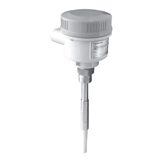
Dimensions Standard Configuration Lid with window 120 mm (4.7") 59 mm (2.3") 76 mm (3") Lid without window 120 mm (4.7") 59 mm (2.3") 76 mm (3") Page 118 Pointek CLS 200 – INSTRUCTION MANUAL 7ML19985AR02... - Page 108 Ø 118 mm (4.7") cable entry: 2 x 1/2" NPT (std.) 2 x M20 x 1.5 (option) aluminum flame- proof enclosure 149 mm (5.2") process connection AISI 316L 122 mm (4.8") PPS insulated sensor 7ML19985AR02 Pointek CLS 200 – INSTRUCTION MANUAL Page 119...
- Page 109 149 mm proof enclosure (5.2") process connection AISI 316L extension part AISI 316L extended length (L1) maximum extended length = 5500 mm (216") Ø 20 mm (0.8") PPS insulated sensor Page 120 Pointek CLS 200 – INSTRUCTION MANUAL 7ML19985AR02...
- Page 110 232mm (9.2") thermal isolator AISI 316L process connection AISI 316L PPS insulated sensor 122 mm (4.8") Thermal Isolator: Detail 3/4" NPT thermal isolator AISI 316L 100 mm (4") 3/4" NPT 7ML19985AR02 Pointek CLS 200 – INSTRUCTION MANUAL Page 121...
- Page 111 Ø 23 mm (0.9") cable entry: 2 x 1/2" NPT (std.) 2 x M20 x 1.5 (option) max. extended length = 5500 mm (216") 156 mm extended length (L1) (6.2") Page 122 Pointek CLS 200 – INSTRUCTION MANUAL 7ML19985AR02...
- Page 112 Pointek CLS 200 with sliding coupling Ø 118 mm (4.7") cable entry 2 x 1/2" NPT (std.) 2 x M20 x 1.5 (option) aluminum flame- proof enclosure 216 mm (8.5") sliding coupling AISI 316L extended max. extended length = length (L1) 5500 mm (216")
-
Page 113: Cable Configuration
= length (L1) 35,000 mm (1378") Appendix C: point, see shortening the cable , on page 99.) sensor weight AISI 316L Ø 20 mm (0.8") PPS insulated sensor Page 124 Pointek CLS 200 – INSTRUCTION MANUAL 7ML19985AR02... - Page 114 2 x M20 x 1.5 (option) (5.2") 30 mm (1.18") 148 mm (5.2") 150 mm aluminum (5.91") flame-proof enclosure bracket FEP insulated cable 70 mm (2.76") sensor side process connection AISI 316L PPS insulated sensor 7ML19985AR02 Pointek CLS 200 – INSTRUCTION MANUAL Page 125...
Need help?
Do you have a question about the Pointek CLS 200 and is the answer not in the manual?
Questions and answers