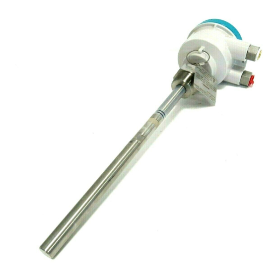
Siemens POINTEK CLS 300 Instruction Manual
Capacitance; liquids/solids
Hide thumbs
Also See for POINTEK CLS 300:
- Application manual (4 pages) ,
- Quick start manual (200 pages) ,
- Operating instructions manual (150 pages)
Table of Contents
Advertisement
Quick Links
Advertisement
Table of Contents

Related Manuals for Siemens POINTEK CLS 300


Summary of Contents for Siemens POINTEK CLS 300
- Page 1 POINTEK CLS 300 CAPACITANCE LIQUIDS/SOLIDS Instruction Manual December 2001...
- Page 2 We welcome versions. all suggestions for improvement. Technical data subject to change. MILLTRONICS®is a registered trademark of Siemens Milltronics Process Instruments Inc. Contact SMPI Technical Publications at the following address: Technical Publications Siemens Milltronics Process Instruments Inc.
-
Page 3: Table Of Contents
Table of Contents Introduction to the Pointek CLS 300 ..................... 2 Pointek CLS 300 Outputs ....................2 Pointek CLS 300 Features ....................2 Pointek CLS 300 Applications..................2 Specifications ..........................3 Installation ............................6 Location ..........................6 Configuration and Dimensions...................... 7 Standard Version......................8 High Temperature Version .....................9 Rod Version........................10... -
Page 4: Introduction To The Pointek Cls 300
Introduction to the Pointek CLS 300 Note: Pointek CLS 300 is to be used only in the manner outlined in this instruction manual. The Pointek CLS 300 capacitance level switch provides output on high or low process material levels. When the measured material is at the desired level, the change in capacitance is sensed and a level alarm is triggered. -
Page 5: Specifications
Other process connections available on request. See Probe: Standard on page 5, or Probe: Cable on page 5. For a chemical resistance list for PFA/Peek /Ceramic, contact your local distributor. See the Pressure/Temperature Curve in Appendix I: Application Notes on p. 25. 7ML19985CK03 Pointek CLS 300 – INSTRUCTION MANUAL Page 3... - Page 6 Max. Load Current: 100mA Voltage Drop Below 1 Volt typical @ 50mA Time Delay (On and/or Off) 1 - 60 sec. Two (2) Wire Switch With customer supplied external trip devices Page 4 Pointek CLS 300 – INSTRUCTION MANUAL 7ML19985CK03...
- Page 7 Insulated: 9mm (0.35" Non insulated: 6mm (0.24" Weight: 32 x 250mm (1.26 x 9.84") Butterfly: 175 x168mm (6.89 x 6.61") Approvals CE, CSA, NRTL/C, FM, CENELEC Please verify against device nameplate. 7ML19985CK03 Pointek CLS 300 – INSTRUCTION MANUAL Page 5...
-
Page 8: Installation
This product is susceptible to electrostatic shock. Follow proper grounding procedures. The Pointek CLS 300 as supplied in the standard probe lengths is normally mounted on the vessel top (high detection alarm) or through the tank wall at the detection level (high or low detection alarm). -
Page 9: Configuration And Dimensions
Configuration and Dimensions (5.8") (5.4") (7.1") (7.5") CABLE/ROPE insulated – 9mm (0.35") non insulated – 6mm (0.24") Ø32 (1.26") 7ML19985CK03 Pointek CLS 300 – INSTRUCTION MANUAL Page 7... -
Page 10: Standard Version
Standard Version 59mm (2.3") 76mm (3") 120mm (4.7") Lid Clip ½” NPT Electronics/ 145mm Enclosure (5.7") Active Shield 370mm (14.6") Probe Ø19mm (0.75") Page 8 Pointek CLS 300 – INSTRUCTION MANUAL 7ML19985CK03... -
Page 11: High Temperature Version
240mm (9.4”) Thermal Isolator Active Shield Note: dependent on probe configuration Probe ∅19mm (0.73”) Warning: Do not cover the Thermal Isolator section of this Point Level Switch device with insulation material. 7ML19985CK03 Pointek CLS 300 – INSTRUCTION MANUAL Page 9... -
Page 12: Rod Version
Place the upper part of the electrode in a vice as shown. Use a wrench to loosen the lower portion of the electrode. Page 10 Pointek CLS 300 – INSTRUCTION MANUAL 7ML19985CK03... - Page 13 The Wrong Way If the process connection itself is put in the vice, the probe’s internal parts will rotate along with the wrench and the unit may fail. 7ML19985CK03 Pointek CLS 300 – INSTRUCTION MANUAL Page 11...
-
Page 14: Cable
Enclosure Active Shield Flexible Extension (Customer - specified length) Cable (82 feet) Insulated – 9mm (0.35") Non insulated – 6mm (0.24") Probe/ Weight 250mm (9.85") Ø32mm (1.26") 175mm (6.9") Page 12 Pointek CLS 300 – INSTRUCTION MANUAL 7ML19985CK03... -
Page 15: Cable Tensile Strength
Make sure that no cable strands are pushed out of their position in the cable and that the cable is fully inserted. Re-fasten the weight by tightening the three set screws. Re-attach Butterfly (if required) to the weight. 7ML19985CK03 Pointek CLS 300 – INSTRUCTION MANUAL Page 13... -
Page 16: Mounting
(20”) min Sensors must be 500mm (20") apart. Mount diagonally if vertical space is restricted. Wall Restriction Note: These drawings are not to scale. 50mm* 50mm* (2”)min (2”)min * standard version Page 14 Pointek CLS 300 – INSTRUCTION MANUAL 7ML19985CK03... -
Page 17: Process Cautions
Caution: Protect probe from falling Caution: Tensile load must not exceed material. probe or vessel rating. 500mm (20”) min Note : buildup of material in active shield area does not affect switch. 7ML19985CK03 Pointek CLS 300 – INSTRUCTION MANUAL Page 15... -
Page 18: Interconnection
250V ac • Maximum working voltage between adjacent relay contacts shall be 250V ac Warning: All field wiring must have insulation suitable for at least 250V ac. Page 16 Pointek CLS 300 – INSTRUCTION MANUAL 7ML19985CK03... -
Page 19: Relay Output Connection
Switch capacity: • 250V ac 100mA max 2VA/2W max • 300V dc. 100mA max relay coil 2VA/2W max Customer supplied diode protection relay coil Customer supplied diode protection 7ML19985CK03 Pointek CLS 300 – INSTRUCTION MANUAL Page 17... -
Page 20: Ancillary 2-Wire Output Connection
Phoenix DEK-OE-5DC/48DC/100 or equivalent) V dc See Power Connection below. Power Connection (3 or 4 wire connection) Nominal 24V dc 48 V dc DC volts 22-26 46-50 R (S) 12 – 250 V (ac/dc) Page 18 Pointek CLS 300 – INSTRUCTION MANUAL 7ML19985CK03... -
Page 21: Operation
Operation Setup Note: Setup can be done in the field with the Pointek CLS 300 mounted into process, or in the shop prior to mounting. Dip Switch 1 • Set ON to change alarm relay status immediately when the sensor detects a change in frequency. -
Page 22: Start Up
L2 (red) = output status: This LED indicates the relay and solid switch contact status. Refer to Operation\Output Status below. L3 (green) = power: This LED is on when the Pointek CLS is properly powered. Page 20 Pointek CLS 300 – INSTRUCTION MANUAL 7ML19985CK03... -
Page 23: Alarm Output
• dry solids • low viscosity liquids • hygroscopic / wet solids • high viscosity and high conductivity liquids Case 2 Interface detection: • e.g. liquid A / liquid B, foam / liquid 7ML19985CK03 Pointek CLS 300 – INSTRUCTION MANUAL Page 21... - Page 24 ON. (If L1 does not light, set S1 switch 5 to ON [normal sensitivity].) Adjust P2 CCW until L1 goes OFF. Immerse the sensor in the material that has the highest dielectric constant; L1 should come ON. Page 22 Pointek CLS 300 – INSTRUCTION MANUAL 7ML19985CK03...
- Page 25 Adjust the delay time from 1 to 60 seconds by setting potentiometer P1 Operation After completing the setup, replace the Pointek CLS lid and lid clip. The unit is now in service, providing level detection of your process. 7ML19985CK03 Pointek CLS 300 – INSTRUCTION MANUAL Page 23...
-
Page 26: Troubleshooting
Maintenance The Pointek CLS 300 requires no regular maintenance or cleaning. Even with significant build- up on the CLS 300 level detector electrode, the level switch will continue to operate. Build-up of material on the active shield area has little or no effect on the performance of the CLS 300. -
Page 27: Appendix I: Application Notes
Appendix I: Application Notes Application Notes Temperature and Pressure Recommendations for Application Note : 1 bar = 100 Pascals 7ML19985CK03 Pointek CLS 300 – INSTRUCTION MANUAL Page 25... -
Page 28: Appendix Ii: Ce Conformity
The notified body: Stoomwezen B.V. – Weena Zuid 168 – 3012 NC Rotterdam – The Netherlands Location: Breda Named Representative: C.S. van Gils Date: Aug 31, 2001 Position: Managing Director Note: For specific safety specifications, please consult the instrument label. Page 26 Pointek CLS 300 – INSTRUCTION MANUAL 7ML19985CK03... -
Page 29: Index
Installation ............6 Standard Version ..........8 Location............6 Dimensions............8 Interconnection ..........16 Start Up..............20 Ancillary 2-Wire Output Connection....18 Diode Protection..........17 Transmitter............4 Power Connection .........18 Trip Amplifier............16 Relay Output Connection ......17 Troubleshooting ..........24 Solid State Switch.........17 7ML19985CK03 Pointek CLS 300 – INSTRUCTION MANUAL Page 27... - Page 30 Notes...
- Page 32 *7ML19985CK03*...
Need help?
Do you have a question about the POINTEK CLS 300 and is the answer not in the manual?
Questions and answers