
Related Manuals for Siemens CSM 1277


Summary of Contents for Siemens CSM 1277
- Page 1 Introduction Network topologies Product characteristics SIMATIC NET Mounting S7-1200 Compact Switch Module Approvals and markings CSM 1277 References Operating Instructions Graphics V. 1.20 A2B00079397B...
- Page 2 Note the following: WARNING Siemens products may only be used for the applications described in the catalog and in the relevant technical documentation. If products and components from other manufacturers are used, these must be recommended or approved by Siemens. Proper transport, storage, installation, assembly, commissioning, operation and maintenance are required to ensure that the products operate safely and without any problems.
-
Page 3: Table Of Contents
Introduction ............................7 Network topologies ............................ 9 Network topologies ........................9 Product characteristics ..........................11 Components of the product......................11 Unpacking and checking......................11 CSM 1277 product characteristics ....................12 TP ports............................13 Displays............................15 Technical specifications .......................16 Mounting..............................19 Installation ............................19 Fixing onto standard mounting rails.....................20 Power supply..........................22... - Page 4 Table of contents Compact Switch Module CSM 1277 Operating Instructions, V. 1.20, A2B00079397B...
-
Page 5: Introduction
The "SIMATIC NET Industrial Ethernet Twisted Pair and Fiber Optic Networks" manual contains additional information on other SIMATIC NET products that you can operate along with the CSM 1277 switch in an Industrial Ethernet network. Finding information To help you to find the information you require more quickly, the manual includes not only the table of contents but also the following sections in the Appendix: ●... - Page 6 1.1 Preface Standards and approvals The CSM 1277 compact switch module meets the requirements for the CE, UL, C-Tick, FM and ATEX marks. You will find detailed information in the section "Approvals and Markings" in this commissioning manual in the "Approvals" table.
-
Page 7: Introduction
The CSM 1277 device allows the cost-effective installation of Industrial Ethernet bus or star structures with switching functionality. Note It is not possible to use the CSM 1277 switch in a redundant ring because it does not support redundancy. Note If the CSM 1277 switch is supplied over long 24 V power supply lines or networks, measures are necessary to prevent interference by strong electromagnetic pulses on the supply lines. - Page 8 Introduction 1.2 Introduction Compact Switch Module CSM 1277 Operating Instructions, V. 1.20, A2B00079397B...
-
Page 9: Network Topologies
Make sure that the maximum permitted cable lengths for the relevant devices are not exceeded. You will find the permitted cable lengths in the technical specifications. Bus topology Figure 2-1 Bus topology with the CSM 1277 Compact Switch Module CSM 1277 Operating Instructions, V. 1.20, A2B00079397B... - Page 10 Network topologies 2.1 Network topologies Star topology Figure 2-2 Star topology. Example with the CSM 1277 Compact Switch Module CSM 1277 Operating Instructions, V. 1.20, A2B00079397B...
-
Page 11: Product Characteristics
Product characteristics Components of the product The CSM 1277 compact switch module ships with the following: ● 3-pin terminal block (power supply) ● Operating Instructions (on the CD) ● CD Unpacking and checking Unpacking, checking 1. Make sure that the package is complete. -
Page 12: Csm 1277 Product Characteristics
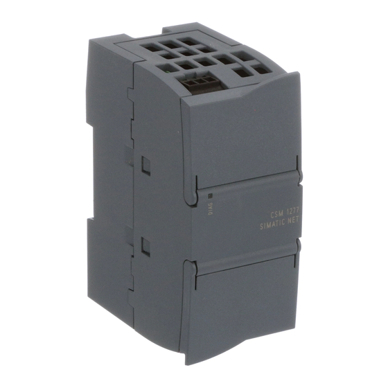
Product characteristics 3.3 CSM 1277 product characteristics CSM 1277 product characteristics Possible attachments The CSM 1277 has four RJ-45 jacks for the connection of end devices or other network segments. Figure 3-1 Compact Switch Module CSM 1277 Compact Switch Module CSM 1277... -
Page 13: Tp Ports
Product characteristics 3.4 TP ports TP ports Connector pinout On the CSM 1277, the TP ports are implemented as RJ-45 sockets with MDI-X assignment (Medium Dependent Interface–Autocrossover) of a network component. Figure 3-2 RJ-45 jacks Figure 3-3 RJ-45 jack Table 3- 1... - Page 14 Devices not supporting autonegotiation must be set to 100 Mbps/ half duplex or 10 Mbps half duplex. Note The CSM 1277 is a plug-and-play device that does not require settings to be made for commissioning. Auto polarity exchange If the pair of receiving cables are incorrectly connected (RD+ and RD- swapped over), the polarity is adapted automatically.
-
Page 15: Displays
Such a loop can lead to network overload and network failures. Displays Displays of the CSM 1277 Power indicator 'DIAG' (green LED) The status of the power supply is indicated by a green LED:... -
Page 16: Technical Specifications
Product characteristics 3.6 Technical specifications Technical specifications Technical specifications of the CSM 1277 Connectors Attachment of end devices or network 4 x RJ-45 sockets with MDI-X pinning components over twisted pair 10/100 Mbps (half/ full duplex), floating Connector for power supply... - Page 17 Note The number of connected switches influences the frame delay. When a frame passes through the CSM 1277, it is delayed by the store and forward function of the switch - with a 64 byte frame length by approx. 8 µs (at 100 Mbps) - with a 1500 byte frame length by approx.
- Page 18 Product characteristics 3.6 Technical specifications Compact Switch Module CSM 1277 Operating Instructions, V. 1.20, A2B00079397B...
-
Page 19: Mounting
Mounting Installation Type of mounting The CSM 1277 compact switch module is intended for mounting on a 35 mm DIN rail. Wall mounting is possible (see S7-1200 System Manual). Note When installing and operating the device, keep to the installation instructions and safety- related notices as described here and in the manual SIMATIC NET Industrial Ethernet Twisted Pair and Fiber Optic Networks /1/. -
Page 20: Fixing Onto Standard Mounting Rails
1. Place the upper guide at the top of the CSM housing in the 35 mm DIN rail (DIN EN 60715 TH35 ). 2. Push in the lower part of the CSM 1277 onto the rail until it locks in place. Figure 4-1... - Page 21 CSM 1277 mounted on a DIN rail Uninstalling To remove a CSM 1277 compact switch module from the DIN rail: 1. First disconnect all connected cables. 2. Using a screwdriver, lever out the catch on the bottom of the device approximately 5 mm while pulling the device away from the rail at the same time.
-
Page 22: Power Supply
Pin assignment of the terminal block Table 4- 1 Pin assignment for the power supply Pin number Assignment Pin 1 L+ (24 V DC) Pin 2 M (chassis ground) Pin 3 Functional ground Compact Switch Module CSM 1277 Operating Instructions, V. 1.20, A2B00079397B... -
Page 23: Grounding
● Standard cables and IE FC RJ-45 Plug 180 connectors that can be assembled in the field for connection of the S7-1200 station to the LAN, for example over greater distances. ● Preassembled cables such as TP Cord RJ-45 0.5 m for connecting the CSM 1277 to the CPU etc. -
Page 24: Fitting The Ie Fc Rj-45 Plug 180
Figure 4-6 IE FC RJ-45 Plug 180 Inserting the IE FC RJ-45 Plug 180 Insert the IE FC RJ-45 Plug 180 into the twisted pair port of the CSM 1277 until it locks in place. Figure 4-7 Inserting the IE FC RJ-45 Plug 180 Compact Switch Module CSM 1277 Operating Instructions, V. -
Page 25: Possible Sources Of Problems And How To Deal With Them
Fuses Note The CSM 1277 compact switch module has a resettable fuse / PTC. If the fuse triggers (all LEDs are off despite correctly applied power supply), the device should be disconnected from the power supply for approximately 30 minutes before turning it on again. - Page 26 Mounting 4.7 Possible sources of problems and how to deal with them Compact Switch Module CSM 1277 Operating Instructions, V. 1.20, A2B00079397B...
-
Page 27: Approvals And Markings
This product is not a machine in the sense of the EC Machinery Directive. There is therefore no declaration of conformity relating to the EC Machinery Directive 98/37/EEC for this product. Compact Switch Module CSM 1277 Operating Instructions, V. 1.20, A2B00079397B... - Page 28 For the temperature code "T.." or the maximum ambient temperature "Ta:..", refer to the type plate. WARNING Explosion hazard! Replacing components will impair the suitability for class I, category 2. Compact Switch Module CSM 1277 Operating Instructions, V. 1.20, A2B00079397B...
-
Page 29: References
2. PROFINET Cabling and Interconnection Technology Guideline Can be ordered from the PROFIBUS User Organization (PNO) Internet Further information on the Internet You will find additional information on SIMATIC NET products in the Internet at http://www.automation.siemens.com/net/index_00.htm Compact Switch Module CSM 1277 Operating Instructions, V. 1.20, A2B00079397B... - Page 30 References 6.2 Internet Compact Switch Module CSM 1277 Operating Instructions, V. 1.20, A2B00079397B...
-
Page 31: Graphics
Graphics Dimension drawings Dimension drawing Figure 7-1 Dimension drawing, view from above Compact Switch Module CSM 1277 Operating Instructions, V. 1.20, A2B00079397B... - Page 32 Graphics 7.1 Dimension drawings Figure 7-2 Dimension drawing, view from side Compact Switch Module CSM 1277 Operating Instructions, V. 1.20, A2B00079397B...
-
Page 33: Glossary
Glossary Aging time The aging time is the time after which a learned MAC address is discarded if a CSM 1277 has not received frames with this sender address during this time. Autocrossover Technique with which a TP port is automatically switched over between MDI and MDI-X assignment to make a connection independent of the port assignment of the device being attached. - Page 34 Glossary TP port Port with a TP connector (RJ-45 jack) Compact Switch Module CSM 1277 Operating Instructions, V. 1.20, A2B00079397B...
-
Page 35: Index
LED display in case of reverse polarity, 25 LED display when voltage is too low, 25 FM approval, 6, 28 Internet, 29 MDI /MDIX autocrossover function, 14 Network topology, 9 Compact Switch Module CSM 1277 Operating Instructions, V. 1.20, A2B00079397B... - Page 36 Index Compact Switch Module CSM 1277 Operating Instructions, V. 1.20, A2B00079397B...
Need help?
Do you have a question about the CSM 1277 and is the answer not in the manual?
Questions and answers