JVA Z14 Installation And User Manual
Security
Hide thumbs
Also See for Z14:
- User manual (96 pages) ,
- Quick start manual (5 pages) ,
- Installer manual (52 pages)

Related Manuals for JVA Z14


Summary of Contents for JVA Z14
- Page 1 SECURITY ENERGIZER Installation and User Manual September 2016 JVA ELECTRIC FENCE SYSTEMS...
- Page 2 JVA ELECTRIC FENCE SYSTEMS Thank you for choosing our product. The JVA brand is a range of electric fencing products carefully selected from leading manufacturers around the world to meet the needs of perimeter security. THE JVA Z RANGE ENERGIZER CONCEPT...
-
Page 3: Table Of Contents
4.18 Group Simultaneous Pulse Feature ..........Perimeter Patrol Lite (2x) Software ............Perimeter Patrol 3.x Software ..............INSTALLATION ..................Installation Steps ................JVA Z14 – Interior Configuration ............Examples of Fence Wiring Diagrams ..........Installation Steps – Group Mode ............. OPERATION ..................... Control ..................... - Page 4 8.6.18 Auto Re-arm Time (20x#) ............ 8.6.19 Relay Functions ..............8.6.20 Relay Options explained ............. 8.6.21 Group Mode (26x#) ............. JVA Z14 ALPHA PLUS LCD KEYPAD FEATURES ........Using the Alpha Plus LCD Keypad ..........Changing the Keypad Messages ............. To Exit Keypad Programming ............
-
Page 5: Introduction
Deterrence – The safe, powerful JVA shock is a strong deterrent to intruders. Delay – The physical barrier will delay an intruder, something they do not like. Detection – The JVA’s voltage monitor warns you of any tampering with the fence. Deny – A well-erected electric security fence will deny entry. -
Page 6: Features And Benefits
JVA ELECTRIC FENCE SYSTEMS 2. FEATURES AND BENEFITS Keypad option– can be used with gives user flexible options up to 3 keypads can customise the energizer to unique Keypad programmable fence conditions Wall-mountable, robust for ease of installation and repair ... -
Page 7: Specifications
JVA ELECTRIC FENCE SYSTEMS 3. SPECIFICATIONS Specification Name Specification Energizer Output Voltage 9kV peak no load Peak Output Energy 5.0 Joules at 500 Ohms, limited to 2.5J in group mode Pulse Rate Locked at 0.9 Hz 12v Dc Power Consumption Energizer On –... -
Page 8: Description
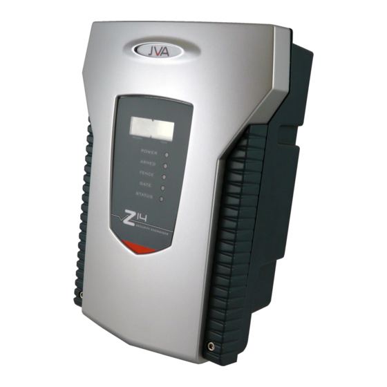
JVA ELECTRIC FENCE SYSTEMS 4. DESCRIPTION 4.1 JVA Z14 Exterior... -
Page 9: Lcd Voltage Display
JVA ELECTRIC FENCE SYSTEMS 4.2 LCD Voltage Display The display on the JVA Z14 shows the voltage at the fence and return terminals. The left is the return and the right is the feed voltage. Arrows at the top of the display indicate that the unit is in conventional mode. -
Page 10: Keypad (Optional)
JVA ELECTRIC FENCE SYSTEMS 4.6 Keypad (0ptional) Up to 3 keypads can be used to remotely monitor and control the Z14. A keypad is required to set the programmable options for installer programming options. See pages 33–35. 4.7 Keypad LCD Screen The JVA Z14 can function with the supplied side-mounted key switch. -
Page 11: Bi-Polar Option
The voltage between the wires is the same as that of a conventional fence. To set a Z14 to Bi-Polar mode, the unit must be modified by a JVA Technical Centre. -
Page 12: Noise And Interference
In the event of erratic behaviour, check that the high voltage wiring is firmly connected to the terminals and that no sparking is seen. The Z14 is designed to self-recover from interference. Powering off (both AC and battery) should not be necessary. -
Page 13: Perimeter Patrol Lite (2X) Software
JVA ELECTRIC FENCE SYSTEMS simultaneous high voltage output pulses and act as if they are one energizer with multiple outputs. This is designed so that no possible combination of individual outputs can be dangerous. See Installation Steps – Group mode... -
Page 14: Installation
Design and build the fence. (Beyond the scope of this manual.) Ask your distributor for help if required. Decide where the JVA Z14 is to be mounted. If on an external wall it should be housed within a waterproof equipment box and definitely not in direct sunlight. -
Page 15: Jva Z14 - Interior Configuration
JVA ELECTRIC FENCE SYSTEMS 5.2 JVA Z14 – Interior Configuration Main board LV terminals HV terminals... -
Page 16: Examples Of Fence Wiring Diagrams
JVA ELECTRIC FENCE SYSTEMS 5.3 Examples of Fence Wiring Diagrams connection Conventional Fence ↑ 1.2m ← 1.2m → ← 1.2m → ↑ Energizer Earth JVA Z14 Energizer configured for conventional fence operation (including earth monitoring) - Page 17 JVA ELECTRIC FENCE SYSTEMS connection Conventional Fence ↑ 1.2m 1.2m 1.2m ←→ ←→ ↑ Energizer Earth JVA Z14 Energizer configured for conventional fence operation (without earth monitoring) - Out Earth + Out - Return Earth + Return Bipolar Fence ↑ 1.2m 1.2m...
-
Page 18: Installation Steps - Group Mode
JVA ELECTRIC FENCE SYSTEMS 5.4 Installation Steps – Group Mode Disarm all energizers in the group. If energizers are not disarmed Step 10 may not work correctly. Program the keypad address using one of the energizers. Program each energizer with its required address (Master address = 1, Slave 1 address = 2...). - Page 19 JVA ELECTRIC FENCE SYSTEMS Z Series Energizer Z Series Energizer PAE 212 Z Series Energizer Z Series Energizer Group Mode Linking Group Installation notes If an Energizer hasn’t been programmed as a Master or a Slave, it is set as “Stand alone”...
-
Page 20: Operation
JVA ELECTRIC FENCE SYSTEMS 6. OPERATION 6.1 Control Your JVA Z14 security energizer has been designed for ease of operation. Key Switch: In its simplest form, the energizer is controlled by the key switch on the side of the unit. -
Page 21: When An Alarm Occurs
JVA ELECTRIC FENCE SYSTEMS 6.4 When an Alarm Occurs If the system is armed and the fence is tampered with, the Fence Light will flash and then remain on. A siren or strobe connected to the unit will turn on. If the energizer is connected to an alarm system for monitoring, an alarm signal will be sent to the alarm company monitoring the alarm system. -
Page 22: Standby Battery
XXXX*22# 6.10 Solar Powering the Unit If there is no mains power on the site, the Z14 can be powered as follows: A 105 Amp/hour battery charged by a 75 watt solar panel. This is a guideline. A bigger panel may be required in some cases. If operating from an externally charged... -
Page 23: Technical Information
JVA ELECTRIC FENCE SYSTEMS 7. TECHNICAL INFORMATION – – Gate Keypad Siren Strobe 16V AC Input Label Type Description 2 Way Energizer control input (dry contact) is in parallel with the key switch input, SW2. Can be used for a remote switch or a radio receiver. The receiver may be powered from the keypad +12V terminal. -
Page 24: Power Options
A PCB fault will disarm the Energizer. If an error disarms the Energizer, the General Alarm and Fence Alarm will be activated. 7.3 Jumpers The Z14 has two special purpose jumpers (links). These are listed in the table below. Jumper Function... -
Page 25: Installation Programming Options
JVA ELECTRIC FENCE SYSTEMS 8. INSTALLATION PROGRAMMING OPTIONS The Z14 has a non-volatile memory in which are held programming options (setup parameters). These are factory pre-set but can be field programmed using a keypad. 8.1 Programming Mode To enter Programming mode, enter the 6-digit INSTALLER PIN followed by *0# keys. -
Page 26: Programming Options In Brief
JVA ELECTRIC FENCE SYSTEMS See page 23 for more detail. Option Function Description Power Level Sets the output power levels Low Power level Sets the output power levels used in Low Power mode Fence Alarm Sets the voltage threshold below which the fence alarm will... -
Page 27: Programming Options In Detail
JVA ELECTRIC FENCE SYSTEMS 8.6 Programming Options in detail Note: The bold panel in each table indicates 8.6.1 Power Level (01x#) the default value. The power level option allows the shocking Value (x) Voltage Voltage power of the fence to be adjusted. For... -
Page 28: Low Power Alarm Level (05X#)
JVA ELECTRIC FENCE SYSTEMS 8.6.4 Low Power Alarm Level (05x#) Value (x) Voltage This option sets the voltage threshold 300 Volts below which the fence alarm will occur. 500 Volts The default Fence Alarm Voltage is 500 700 Volts Volts. -
Page 29: Siren On Time (08X#)
JVA ELECTRIC FENCE SYSTEMS 8.6.7 Siren On Time (08x#) Value Time This option sets the duration of time that 10 Seconds the siren will remain on after a fence alarm 30 Seconds occurs. After this time the siren will turn off 1 Minute for the Off time indicated in Table 8.6.8. -
Page 30: Input Inversion (11X#)
JVA ELECTRIC FENCE SYSTEMS Value Function 8.6.10 Input Inversion (11x#) Normally open The control inputs can be inverted, Normally closed unless an input is used for a Gate switch, Momentary Input in which case it is always NC. Input Inversion (11x#) 8.6.11 Gate Input Function/Low... -
Page 31: Fence Mode(15X#)
Zone on a Z28. Added in code version Binary Options (16x#) 7.84. Also limits a Z14 to 2.5J per zone in group mode. Added 7.86. +8: Enables the IR tamper detection under the lid. J3 changes function to inhibit tamper. -
Page 32: Binary Options 2 (18X#)
JVA ELECTRIC FENCE SYSTEMS The Anti-bridging Threshold is a percentage value of the current Fence Voltage. For example, setting option 17 to 10 (1710#) will set a 10% Anti-bridging Threshold. At this level a fence (return) voltage normally reading 7.5kV will trigger a Fence Alarm if the voltage quickly rises to over 8.3kV or falls to less than 6.7kV. -
Page 33: Auto Re-Arm Time (20X#)
Fence 2 Fence 2 or off Even though the three additional relays Armed 2 are not fitted to the Z14, Relays 3, 4 and 5 can still be programmed. The modes Fence Bi-Polar are explained in the table opposite. General... -
Page 34: Relay Options Explained
JVA ELECTRIC FENCE SYSTEMS 8.6.20 Relay Options explained Function Logic for alarm state (opposite of normal state) Fence x Fence x Alarm: Zone x is Armed (Pulsing) AND the Fence Return Voltage has fallen below the Fence Alarm Voltage for more pulses than the Missed Pulse Count. -
Page 35: Jva Z14 Alpha Plus Lcd Keypad Features
JVA ELECTRIC FENCE SYSTEMS 9. JVA Z14 ALPHA PLUS LCD KEYPAD FEATURES 9.1 Using the Alpha Plus LCD Keypad The LCD keypad has two LEDs, Power and Arm, which act as follows: Power: On with Mains power, flashes on low battery. -
Page 36: Changing The Keypad Messages
JVA ELECTRIC FENCE SYSTEMS 9.2 Changing the Keypad Messages You can change the messages and each of the 8 zone labels. ● The Dealer Message displays when the system is on standby. ● Zone Labels displays after the [#] key is pressed during alarm memory or faults. -
Page 37: To Exit Keypad Programming
JVA ELECTRIC FENCE SYSTEMS The message order is: ● Service Message (Displayed under “System Trouble”) ● Dealer Message (Displayed under the standby message: “Ready to Arm”) ● Soft Zone Identifiers (A, B, And C) (not used) ● Hardwired Loop Identifiers (Zone 1 = Gate, Zone 3 = Fence) ●... -
Page 38: Sector Setup Tests And Adjustment
JVA ELECTRIC FENCE SYSTEMS 10. SECTOR SETUP TESTS AND ADJUSTMENT With a single sector system there are two considerations for the electric fence monitor voltage level: 1. The monitor should trigger the alarm if one of the live wires is shorted to ground. - Page 39 JVA ELECTRIC FENCE SYSTEMS 1. To simulate a break, disconnect a joint in the live wires at some convenient point on the fence, making sure that the wires do not short to ground or between +ve and -ve wires. 2. Check that the energizer fence alarm activates. If not, check the voltage (using an electric fence voltmeter) at the inputs to the monitor.
-
Page 40: Some Standard Requirements For Electric Security Fences
11. SOME STANDARD REQUIREMENTS FOR ELECTRIC SECURITY FENCES The JVA range of energizers has been extensively tested and certified in accordance with international standards. JVA does not take responsibility for the erection standards of the fence. It is the responsibility of the erector to consult and comply with the Standards and Codes of Practice for the installation and erection of electric security fences. -
Page 41: Warning Signs
* NB. (Fence HT leads must under no circumstances be routed in the same conduit as any other wiring.) 11.3 Warning Signs NOTE: Regulation warning signs are available from all JVA Electric Fence centres and all JVA certified dealers. 11.3.1 Electric security fences shall be identified by prominently placed warning signs that shall be legible from the secure area and from the public area. -
Page 42: Protection
JVA ELECTRIC FENCE SYSTEMS 11.6 Protection 11.6.1 All ancillary equipment connected to the fence circuit shall be designed to provide a degree of isolation between a fence circuit and the supply mains equivalent to that specified for the energizer. 11.6.2 Protection from weather shall be... - Page 43 JVA ELECTRIC FENCE SYSTEMS Figure 2 Typical fence constructions where the electric security fence is installed in windows and skylights.
- Page 44 JVA ELECTRIC FENCE SYSTEMS Figure 3 Prohibited zone for pulsed conductors. CUSTOMISED CODES Customer Pin No..... Installer Pin No: ....... INSTALLER DETAILS Name ............Phone No..........Date Of Installation ........
-
Page 45: Warranty
Whilst every effort has been made to check that the information contained is accurate, JVA Technologies Pty Ltd will not be liable to loss or damage resulting from construction, operation or failure of any installation or system. Installation of security electric fences should be made by trained professionals with regard to the relevant local standards and workplace health and safety requirements. - Page 46 JVA ELECTRIC FENCE SYSTEMS...
-
Page 47: Customer Support
JVA dealer. SA Tel. No.: 0861 782 349. For service or repairs: If a service or repair is required, please package and label your energizer carefully and return it to your local JVA Service Centre. For warranty repairs: Include proof of purchase, e.g. invoice. - Page 48 JVA ELECTRIC FENCE SYSTEMS JVA products are designed by JVA Technologies, Queensland, Australia and distributed to: CARIBBEAN CENTRAL AMERICA AFRICA AUSTRALIA CENTRAL ASIA INDIA LATINO AMERICA EUROPE NEW ZEALAND PHILIPPINES PAkISTAN MEXICO RUSSIA SOUTH EAST ASIA SRI LANkA UNITED kINGDOM...
Need help?
Do you have a question about the Z14 and is the answer not in the manual?
Questions and answers
bonjour, code erreur n°16
Error code 16 on the JVA Z14 indicates a communication failure, which triggers a programmable Service Message.
This answer is automatically generated
On the jva z14 if the fence are activated it give me a 9L code what can it be. The lines are cleare