Table of Contents
Advertisement
JVA ELECTRIC FENCE SYSTEMS
1
INTRODUCTION ...................................................................................
2
FEATURES AND BENEFITS ................................................................
2.1
More Features .........................................................................................
3
SPECIFICATIONS .................................................................................
4
DESCRIPTION ......................................................................................
4.1
JVA Z114 - Exterior .................................................................................
4.2
Front Panel Status Lights ........................................................................
4.3
Front Panel LCD Display .........................................................................
4.4
Inputs and Outputs ..................................................................................
4.5
Status Codes ...........................................................................................
4.6
Keypad (Optional) ...................................................................................
4.7
Z Series Models ......................................................................................
4.8
Keypad (Optional) ...................................................................................
4.9
Internal Beeper/Keypad Beeper ..............................................................
4.10 Programmable Options ...........................................................................
4.11 Arm input (control input 1) and Key Switch .............................................
4.12 Gate Input (control input 2) .....................................................................
4.13 Low Power mode ....................................................................................
4.14 Group Simultaneous Pulse Feature ........................................................
4.15 Remote Control Unit (Optional) ...............................................................
4.16 Cabling ....................................................................................................
4.17 Lightning Protection ................................................................................
4.18 Earth Loop Monitoring .............................................................................
4.19 Noise and Interference ............................................................................
4.20 PC control ...............................................................................................
4.21 Web Server .............................................................................................
5
INSTALLATION ......................................................................................
5.1
Installation Steps .....................................................................................
5.2
JVA Z114 - Interior Configuration ...........................................................
5.3
Examples of Fence (High Voltage) Wiring Diagrams ..............................
5.4
Control .....................................................................................................
5.5
Turning to Low Power Mode ...................................................................
5.6
When an Alarm Occurs ...........................................................................
5.7
To Silence the Alarm ...............................................................................
CONTENTS
4
5
5
6
7
7
7
8
8
8
8
8
9
9
9
9
9
10
10
10
10
10
11
11
11
11
12
12
13
14
15
15
15
16
1
Advertisement
Table of Contents

Related Manuals for JVA Z Series


Summary of Contents for JVA Z Series
-
Page 1: Table Of Contents
CONTENTS INTRODUCTION ................... FEATURES AND BENEFITS ..............More Features ..................SPECIFICATIONS ................. DESCRIPTION ..................JVA Z114 – Exterior ................. Front Panel Status Lights ................ Front Panel LCD Display ................. Inputs and Outputs .................. Status Codes ................... Keypad (Optional) ................... Z Series Models .................. - Page 2 JVA ELECTRIC FENCE SYSTEMS Changing the PIN Number ..............Standby Battery ..................5.10 Status Light ..................... TECHNICAL INFORMATION ............... Power Options ..................Status Codes ................... Jumpers ....................6.4 Configuring a Z114 to run in Bi-Polar mode ..........INSTALLATION PROGRAMMING OPTIONS ........Programming Mode ................. To Exit Programming Mode ..............
- Page 3 JVA ELECTRIC FENCE SYSTEMS JVA Z114 LCD KEYPAD FEATURES ........... Keypad status LEDs ................8.1.1 Arming/Disarming the Fence Using the Keypad ........8.1.2 Menus ..................... 8.1.3 Keypad Status Display ................8.1.4 Changing the Keypad Messages and Address ........To Exit Keypad Programming ..............
-
Page 4: Introduction
JVA ELECTRIC FENCE SYSTEMS 1. INTRODUCTION Thank you for purchasing a JVA security electric fence energizer. The growing use of non-lethal electric security fences around the world is indicative of the confidence security professionals are placing in this form of perimeter security. The reason for this popularity is simple – monitored electric security fences are effective and they reduce false alarms when compared to other technologies. -
Page 5: Features And Benefits
JVA ELECTRIC FENCE SYSTEMS 2. FEATURES AND BENEFITS • Australian designed and High reliability and great service manufactured • Programmable Options Customise the energizer to unique fence conditions • Wall-mountable, robust Ease of installation and repair enclosure with easily detachable PCB chassis • Inbuilt LCD voltage... -
Page 6: Specifications
JVA ELECTRIC FENCE SYSTEMS 3. SPECIFICATIONS Specification Name Specification Energizer Output Voltage 9.5kV peak no load Peak Output Energy 14 Joules at 200 Ohms Pulse Rate Locked at 0.8 Hz 12v Dc Power Consumption Energizer On – 1.40A Average, 2.0A peak Energizer Off –... -
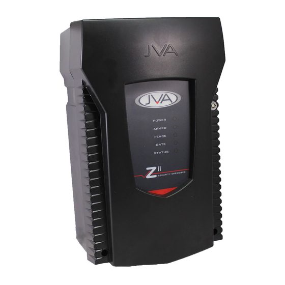
Page 7: Description
JVA ELECTRIC FENCE SYSTEMS 4. DESCRIPTION JVA Z114 – Exterior Front Panel Status Lights POWER On whenever the unit has power ARMED On when the unit is armed (pulsing), will flash when in Low Voltage mode FENCE Red when there is a fence alarm GATE On when there is a gate alarm The number of times the Status Light flashes indicates the status of the STATUS energizer. -
Page 8: Front Panel Lcd Display
JVA ELECTRIC FENCE SYSTEMS Front Panel LCD Display The display on the JVA Z114 shows the voltage at the fence and return terminals. The left is the return and the right is the feed voltage. Arrows at the top of the display indicate that the Energizer is in conventional mode. When configured for Bi-Polar... -
Page 9: Keypad (Optional)
Section7.6. Each parameter has a factory set default. 4.11 Arm input (control input 1) and Key Switch The JVA Z series energizer can be armed (to energize the fence) by closing a contact wired into the arm input. On some models a key switch is fitted to the right-hand side of the case for this purpose. -
Page 10: Low Power Mode
In some installations it may be preferable to provide the ability to link multiple units into a group. When linked, the individual Z series energizers become a Group. As many as fifteen energizers can be grouped. Individual units in a Group have simultaneous high voltage output pulses and act as if they are one energizer with multiple outputs. -
Page 11: Earth Loop Monitoring
4.20 PC control A standard Windows PC may be used to control and monitor a group of Z series energizers. Ask your JVA distributor for a demonstration of Perimeter Patrol ™ software. Z series energizers can be connected to a PC using either a serial data adaptor, such as the PAE223 or TCP/IP using a PAE212. -
Page 12: Installation
Design and build the fence. (Beyond the scope of this manual.) Ask your distributor for help if required. Decide where the JVA Z114 is to be mounted. If on an external wall it should be housed within a waterproof equipment box and definitely not in direct sunlight. Remove the JVA Z114 PCB chassis from the housing by removing the 2 screws. -
Page 13: Jva Z114 - Interior Configuration
JVA ELECTRIC FENCE SYSTEMS 5.2 JVA Z114 – Interior Configuration (Above) High Voltage Terminals (Right) Low Voltage Terminals... -
Page 14: Examples Of Fence (High Voltage) Wiring Diagrams
JVA ELECTRIC FENCE SYSTEMS Examples of Fence (High Voltage) Wiring Diagrams Z114 Energizer configured for conventional fence operation Z114 Energizer configured for Bi-polar operation... -
Page 15: Control
JVA ELECTRIC FENCE SYSTEMS Control Your JVA Z114 security energizer has been designed for ease of operation. Key Switch: In its simplest form, the energizer is controlled by the key switch on the side of the unit. Keypad: The energizer can be installed in a convenient location close to the fence, while the keypad can be positioned in an easily accessible place. -
Page 16: Changing The Pin Number
JVA ELECTRIC FENCE SYSTEMS To Silence the Alarm • Enter your PIN and press #. This will silence the alarm but not disarm the system; the Armed Light will still be on. The system will be ready for the next alarm. (Note that the following functions have an effect on alarm timing: Siren On time, Siren Off time, Siren Cycles, Auto Re-arm time). • The siren and strobe are ready to respond again if triggered. • To disarm the system, enter your PIN and press # again. This will also clear the fence alarm light. -
Page 17: Technical Information
JVA ELECTRIC FENCE SYSTEMS 6. TECHNICAL INFORMATION Low Voltage Terminals Label Type Description 2 Way Energizer control input 1 (dry contact normally open) internally wired in parallel with the key switch. Can be used for a remote switch or a radio receiver. -
Page 18: Power Options
JVA ELECTRIC FENCE SYSTEMS Power Options The Z114 has 2 sources of power, 16VAC and 12VDC (Battery). If using solar power and an external battery, connect the battery to the battery leads, not the 16Vac input. A 24Vdc 2.5A supply can be used in place of the 16Vac supply. The correct connection is +24V to the mid AC pin, GND to the left AC pin. -
Page 19: Jumpers
JVA ELECTRIC FENCE SYSTEMS Jumpers Jumper Function Purpose J3 is fitted to inhibit Mains fail errors if the Inhibit Mains fail error. intention is to operate the energizer on DC only (as in solar power systems). If the energizer needs to be defaulted to factory Factory default jumper settings, remove all power (AC and battery) and Off to return programmable remove the J4 jumper. Reapply the mains and... -
Page 20: Installation Programming Options
JVA ELECTRIC FENCE SYSTEMS 7. INSTALLATION PROGRAMMING OPTIONS The Z114 has a non-volatile memory in which are held programming options (setup parameters). These are factory pre-set but can be field programmed using a keypad. Programming Mode To enter Programming mode, enter the 6-digit installer PIN followed by *0# keys. The keypad will beep twice to indicate that the command was accepted. If the PIN was incorrect, the keypad will beep 3 times. Pressing the # key will cycle through all the options on the LCD. -
Page 21: Programming Options In Brief
JVA ELECTRIC FENCE SYSTEMS Programming Options in Brief See Section 7.6 for more detail. Option Function Description Programming Options Power Level Sets the output voltage level Low Power level Sets the output power levels used in Low Power mode Fence Alarm... -
Page 22: Programming Options In Detail
JVA ELECTRIC FENCE SYSTEMS Programming Options in Detail NOTE: The bold panel in each table indicates the default value. 7.6.1 Power Level (01x#) The power level option allows Voltage: Voltage: Value (x) the shocking power of the fence Conventional mode Bi-Polar Mode to be adjusted. For example:... -
Page 23: Fence Alarm Voltage (03X#)
JVA ELECTRIC FENCE SYSTEMS 7.6.3 Fence Alarm Voltage (03x#) This option sets the voltage Voltage: Voltage: Value (x) threshold below which the fence Conventional mode Bi-Polar Mode alarm will occur. The default 1.5kV 1.5kV Fence Alarm Voltage is 4 kV in 2.0kV... -
Page 24: Battery Alarm Voltage (07X#)
JVA ELECTRIC FENCE SYSTEMS 7.6.6 Battery Alarm Voltage (07x#) Keypad Alarm Reduce Power This option sets the battery voltage number threshold below which the alarm will 9.0 V 8.0 V activate. The default Battery Alarm Voltage 9.5 V 8.5 V is 10.0 Volts and the unit will drop to low... -
Page 25: Siren Cycles (10X#)
JVA ELECTRIC FENCE SYSTEMS 7.6.9 Siren Cycles (10x#) Value Cycles This option sets the maximum number of times the siren will sound for the “On time” if the alarm continues. This may be limited by local regulations to stop an alarm causing undue disturbance to neighbours, etc. -
Page 26: Chime Mode (14X#)
JVA ELECTRIC FENCE SYSTEMS 7.6.13 Chime Mode (14x#) This option allows the energizer internal and Value Function keypad beeper to be used as a door chime for the None gate switch. When set to None, the keypad beeper Door Chime is used to indicate correct keypad operation only. -
Page 27: Anti-Bridging Threshold (17X#)
JVA ELECTRIC FENCE SYSTEMS 7.6.15 Anti-Bridging threshold (17x#) Anti-bridging has been designed to detect a section of fence being bypassed, and removed from circuit, by an intruder bridging the feed to returns together and then cutting the live wires in between. Setting this option to a value greater than 0 (default is 0 = off) will enable Anti-bridging, however this feature will not operate in low power mode! While Armed, a Fence Alarm will trigger if the Fence Voltage rises OR falls quickly by more than the threshold. A... -
Page 28: Auto Re-Arm Time (20X#)
• Relay 5 – General (Note: Relay 5 is not Tamper physically fitted to PCB) Strobe 2 NOTE: Optional extra relays can be retro- Gate 1 or 2 fitted. Contact your nearest JVA service Siren caused by Gate centre for details. 1 or 2 Armed in Low Power Notes: Mode 1. -
Page 29: Group Mode (26X#)
JVA ELECTRIC FENCE SYSTEMS Function Logic for alarm state (opposite of normal state) Fence x Fence x Alarm: Zone x is Armed (Pulsing) AND the Fence Return Voltage has fallen below the Fence Alarm Voltage for more pulses than the Missed Pulse Count. -
Page 30: Jva Z114 Lcd Keypad Features
JVA ELECTRIC FENCE SYSTEMS 8. JVA Z114 LCD Keypad Features Keypad status LEDs The LCD keypad has two LEDs, Power and Arm, which act as follows: • Power: On with Mains power, flashes on low battery. • Arm: On When the energizer is armed (pulsing), flashes when in Low Power Mode. 8.1.1 Arming/Disarming the Fence Using the Keypad Enter your User PIN (Personal Identification Number: four digits long) and push the # key. Make sure the red ARM light comes on and the keypad beeps twice to confirm that the system is armed. -
Page 31: Menus
JVA ELECTRIC FENCE SYSTEMS 8.1.2 Menus The Z series keypad has an optional menu driven interface. The main menu is accessed by pressing the Menu (Bypass) key (bottom right). You will be asked to enter your PIN, and then press #. -
Page 32: To Exit Keypad Programming
JVA ELECTRIC FENCE SYSTEMS • To activate the keypad programming mode, enter the [Installer’s Code] [*] [0] [1] [#]. Information may be entered into the keypad in the form of letters (upper and lower case), numbers (0–9), and 22 special symbols. All characters are displayed in the order: upper and lower case letters, numbers, and special symbols. -
Page 33: Connecting Multiple Keypads To A System
JVA ELECTRIC FENCE SYSTEMS 8.3 Connecting Multiple Keypads to a system Up to three keypads may be used to remotely monitor and control the Z series security energizers. To operate correctly, each Keypad must be configured to use a unique KEYPAD ADDRESS. -
Page 34: Summary Of Lcd Keypad Functions
Function Description Arm/Disarm [User PIN][#] Silence an alarm (Single zone system only) [User PIN][#] Start Programming the Z series energizer [Installer PIN][*] [0] [#] Start Programming the Keypad [Installer PIN][*] [0] [1] [#] Exit Programming (any mode) [*] [#] Change a User PIN, 4 Digits... -
Page 35: Remote Control Unit
JVA ELECTRIC FENCE SYSTEMS 9. Remote Control Unit The Remote Control Unit provides the Z114 with the ability to arm or disarm the energizer via a compact key chain fob remote control. Two remote controls are provided, and are uniquely coupled to the receiver using a rolling code algorithm to ensure security. -
Page 36: Installation
JVA ELECTRIC FENCE SYSTEMS Installation The Remote control receiver unit requires 12V and 0V (GND) from the keypad bus, and its output is shown wired to IN1. Mount the receiver on the right hand side of the Z114 energizer. Connect +12V and 0V (GND) from the KEYPAD terminals on the energizer to the right-most terminals of the receiver, as per the diagram above. -
Page 37: Standard Requirements For Security Electric Fences
JVA ELECTRIC FENCE SYSTEMS 10. Standard Requirements for Security Electric Fences 10.1 Definitions Connecting lead An electric conductor, used to connect the energizer to the electric fence or the earth electrode Electric animal An electric fence used to contain animals within or exclude... - Page 38 JVA ELECTRIC FENCE SYSTEMS The size of the warning plates shall be at least 100 mm × 200 mm. The background colour of both sides of the warning plate shall be yellow. The colour on the Figure 7 – Warning...
-
Page 39: Particular Requirements For Electric Animal Fences In Australia
JVA ELECTRIC FENCE SYSTEMS 10.3 Particular requirements for electric animal fences in Australia 15. A distance of at least 10 m shall be maintained between the energizer earth electrode and any other earthing system such as the power supply system protective earth or the telecommunication system earth. -
Page 40: Prohibited Zone For Pulsed Conductors
JVA ELECTRIC FENCE SYSTEMS 10.4.3 Prohibited zone for pulsed conductors Pulsed conductors shall not be installed within the shaded zone shown in Figure 8. Figure 8 – Prohibited Area for Pulse Conductors Note 1: Where an electric security fence is planned to run close to a site boundary, the relevant government authority should be consulted before installation begins. -
Page 41: Separation Between Electric Fence And Physical Barrier
JVA ELECTRIC FENCE SYSTEMS Note 2: Typical electric security fence installations are shown in Figure 9 and Figure 10. Figure 10 – Typical fence constructions where the electric security fence is installed in windows and skylights 10.4.4 Separation between electric fence and physical barrier... -
Page 42: Prohibited Mounting
JVA ELECTRIC FENCE SYSTEMS 10.4.5 Prohibited mounting Electric fence conductors should not be mounted on a support used for any overhead power line. 10.4.6 Operation of electric security fence The conductors of an electric fence should not be energized unless all authorized persons, within or entering the secure area, have been informed of its location. -
Page 43: Appendix A: Group Simultaneous Pulse Feature
Group Simultaneous Pulse Feature In some Industrial Installations it may be preferable to provide the ability to link multiple Energizers into a group. When linked the individual Z Series Energizers become a “Group”. Members of a group have simultaneous high voltage output pulses and act as is they are one energizer with multiple outputs. -
Page 44: Group Linking Via The Keypad "Bus
JVA ELECTRIC FENCE SYSTEMS Group linking via the Keypad “bus” The keypad terminals on all Energizers in the group are linked. Since only one Energizer needs to power the keypad, 3 wires are linked from one Energizer (preferably the Master) to the keypad (optional) and 2 wires to every other Energizer in the group. - Page 45 JVA ELECTRIC FENCE SYSTEMS 5. When connected to Perimeter Patrol, the arm/disarm function of a keypad is disabled. Control of these functions is through the Perimeter Patrol interface. 6. A Keypad that is connected to a Slave Energizer that is disconnected from the Group, must have a KEYPAD ADDRESS set to 1.
- Page 46 INSTALLER DETAILS CUSTOMISED CODES Name ............. Customer Pin No......Phone No............Installer Pin No: ......Date Of Installation ........
- Page 47 Whilst every effort has been made to check that the information contained is accurate, JVA Technologies Pty Ltd will not be liable to loss or damage resulting from construction, operation or failure of any installation or system. Installation of security electric fences should be made by trained professionals with regard to the relevant local standards and workplace health and safety requirements.
- Page 48 JVA ELECTRIC FENCE SYSTEMS NOTES...
Need help?
Do you have a question about the Z Series and is the answer not in the manual?
Questions and answers