Advertisement
Quick Links
Advertisement

Subscribe to Our Youtube Channel
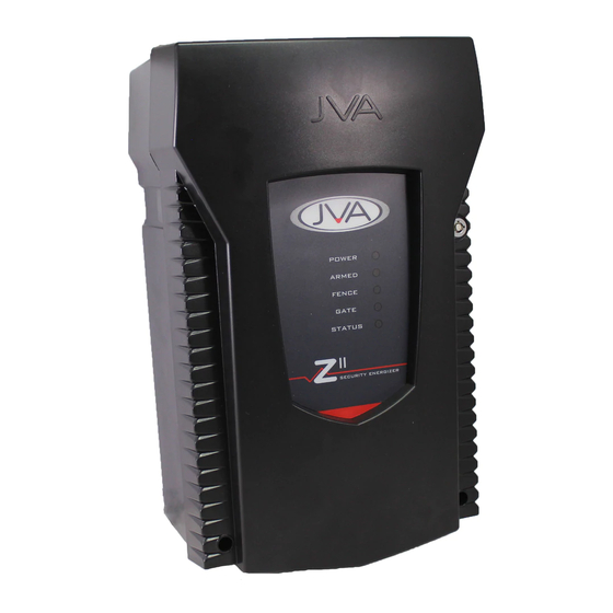
Summary of Contents for JVA Z Series
- Page 1 J VA T E CH N O LO G I E S www.jva-fence.com...
-
Page 2: Low Voltage Wiring
SIREN 2 Way Switched 12V output. 30W max, shared between Si- ren and Strobe. Low side switched STROBE 2 Way Switched 12V output. 30W max, shared between Si- ren and Strobe. Low side switched Page 2 © JVA Technologies www.jva-fence.com... - Page 3 Off to return programmable options to factory defaults on power up. Disable on board beeper J5, J6 & J7 Supplies +12V to the Common terminal of Relay 3, 4, 5. Jumpers located on the top right hand side of the board Z Series Quick Start Manual Page 3...
- Page 4 Arm the energizer once again, after 3 pulses (unless you configured it oth- erwise) the unit should go into alarm as the fence will appear to be cut. Check that any sirens, strobes or relays activate as expected. Page 4 © JVA Technologies www.jva-fence.com...
- Page 6 CHANGING THE PROGRAMMING OPTIONS Default Installer PIN 012345 Default User PIN 1234 First you have to enter Programming mode. Command Key1 Key2 Key3 Key4 Key5 Key6 Key7 Key8 Key9 Enter Programming Mode Installer Pin When you have entered Programming mode you can begin to enter the following options to configure your Security Energizer.
- Page 7 Command Key1 Key2 Keys 3 and 4 Key5 Return Fence Alarm Enter the value in Hundreds of Volts Voltage For High Example: to set 3.8kV, use 38 for keys 3 and 4. Default is 40 (4.0kV) Power Mode Return Fence Alarm Enter the value in Hundreds of Volts Voltage For Low Example: to set 0.8V, use 08 for keys 3 and 4.
- Page 8 Command Key1 Key2 Keys 3 and 4 Key5 Gate Entry/Exit Delay (S=Seconds, M=Minutes) Chime Mode None Door Chime Siren Fence Gate Beeps Alarm Plus Siren Combined Options 1 Maximum Limits out- Enables IR Stop slaves Stop Ener- (add up the options Power at all put to 2.5J Tamper.
- Page 9 Command Key1 Key2 Keys 3 and 4 Key5 Combined Options 2 +128 (like Combined Siren Enable 4800 9600 Bite to Options 1) Chirp Entry Baud Baud Power Exit to Bite Power Gate Auto Re-arm Time S=Seconds, M = Min- utes, D=Disabled Relay 1 Options Explained under “1.6.1 Relay Functions”...
- Page 10 Command Key1 Key2 Keys 3 and 4 Key5 Exit Programming Mode 1.6.1 Relay Functions The table below is for use for the relay programming options mentioned in the table on the previous page. Keys 3 Function Description and 4 Fence Triggers when Zone 1 is Armed and Return Voltage is below the Threshold Voltage Fence or Off Triggers when Zone 1 is Disarmed or Return Voltage is below the Threshold Voltage...
- Page 11 Keys 3 Function Description and 4 Gate Triggers on Gate Alarm Siren Caused by Behaves like siren, only for Gate Alarms Gate Armed - Low Triggers when Armed in Low Power mode Power Mode Group Armed Triggers when group is Armed. Only configurable on group master. Group general Triggers on group general Alarm.
- Page 12 1.6.2 Input Functions Key3 Input Trigger Key4 Input Function Normally Open (Active when Closed) Arm when Active / Disarm otherwise Normally Closed (Active when Open) Arm when Active / Disarm otherwise Momentary Toggle (Toggle between states) NO Pulse Extend (Extend a short Close signal by Low Power when Active / High Power otherwise.
-
Page 13: Summary Of Keypad Functions
SUMMARY OF KEYPAD FUNCTIONS Default Installer PIN 012345 Default User PIN 1234 Command Key1 Key2 Key3 Key4 Key5 Key6 Key7 Key8 Key9 Key10 Arm/Disarm USER PIN Silence the Energizer Siren Enter Programming Mode INSTALLER PIN Enter Keypad Programming Mode INSTALLER PIN Exit Programming (Any Mode) Change a User PIN, 4 Digits USER PIN... - Page 14 Command Key1 Key2 Key3 Key4 Key5 Key6 Key7 Key8 Key9 Key10 Switch to High Power Mode (All Zones) USER PIN Switch Specific Zone to High Power USER PIN Zone No. Arm Gate Zone only USER PIN Bypass Siren (All Zones) USER PIN Bypass Specific Zone Siren USER PIN...
- Page 15 Energizer Function Key1 Key2 Key3 Key4 Clear Alarm Memory Display the Group ID of the Energizer Siren Test Battery Test Keypad Specific Function Key1 Key2 Key3 Key4 Re-Analyse the Energizer Group Keypress Beep On/Off Chimes On/Off Error Tones On/Off Keypad Alarm Tones On/Off Change Backlight Mode Display Keypad Model...
- Page 16 DEALER fEncE...


Need help?
Do you have a question about the Z Series and is the answer not in the manual?
Questions and answers