
Related Manuals for JVA Z114


Summary of Contents for JVA Z114
- Page 1 HI POWER SECURITY ENERGIZER Installation and User Manual Edition 1, 2014 JVA ELECTRIC FENCE SYSTEMS...
- Page 2 JVA ELECTRIC FENCE SYSTEMS Thank you for choosing our product. The JVA brand is a range of electric fencing products carefully selected from leading manufacturers around the world to meet the needs of perimeter security. THE JVA Z RANGE ENERGIZER CONCEPT...
-
Page 3: Table Of Contents
When an Alarm occurs ................To silence the Alarm ................changing the pIn number ..............standby Battery ..................5.10 status Light ..................... TecHnIcAL InForMATIon ............... power options ..................status codes ................... Jumpers ....................Configuring a Z114 to run in Bi-Polar Mode .......... - Page 4 Auto re-arm Time (20x#) ............7.6.18 relay Functions ................ 7.6.19 Group Mode (26x#) ..............JVA Z114 Lcd KeypAd FeATures ........... Keypad status Leds ................8.1.1 Arming/disarming the Fence using the Keypad ........8.1.2 Menus ..................... 8.1.3 Keypad status display ................
-
Page 5: Introduction
JVA ELECTRIC FENCE SYSTEMS 1. INTRODUCTION Thank you for purchasing a JVA security electric fence energizer. The growing use of non-lethal electric security fences around the world is indicative of the confidence security professionals are placing in this form of perimeter security. The reason for this popularity is simple –... -
Page 6: Features And Benefits
JVA ELECTRIC FENCE SYSTEMS 2. FEATURES AND BENEFITS • Australian designed and High reliability and great service manufactured • programmable options customise the energizer to unique fence conditions • Wall-mountable, robust ease of installation and repair enclosure with easily detachable pcB chassis • Inbuilt Lcd Voltage... -
Page 7: Specifications
JVA ELECTRIC FENCE SYSTEMS 3. SPECIFICATIONS Specification Name Specification energizer output Voltage 9.5kV peak no load peak output energy 14 Joules at 200 ohms pulse rate Locked at 0.8 Hz 12v dc power consumption Energizer On – 1.40A Average, 2.0A peak Energizer Off –... -
Page 8: Description
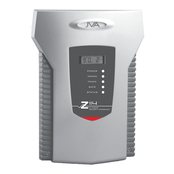
JVA ELECTRIC FENCE SYSTEMS 4. DESCRIPTION JVA Z114 – Exterior Front Panel Status Lights poWer on whenever the unit has power ArMed On when the unit is armed (pulsing), will flash when in Low Voltage Mode Fence red when there is a fence alarm... -
Page 9: Front Panel Lcd Display
Status Codes see section 6.2. Keypad (Optional) A keypad can be used to remotely monitor and control the Z114. It is also used to set the programmable options for installer programming options, see Section 8. Z Series Models Single Zone, conventional 1.5 Joule Single Zone, conventional 2.8 Joule... -
Page 10: Keypad (Optional)
4.11 Arm Input (control input 1) and Key Switch The JVA Z series energizer can be armed (to energize the fence) by closing a contact wired into the arm input. On some Models a key switch is fitted to the right-hand side of the case for this purpose. -
Page 11: Low Power Mode
4.15 Remote Control Unit (Optional) The remote control unit provides the Z114 with the ability to arm or disarm the energizer via a compact key chain fob remote control. If using the remote control the siren can be used to acknowledge arming with 1 beep and disarm with 2 beeps. see 7.6.13. -
Page 12: Earth Loop Monitoring
JVA ELECTRIC FENCE SYSTEMS 4.18 Earth Loop Monitoring The Z114 has two fence earth terminals. If the earth monitoring facility is not required, the Earth Out and Earth Return terminals must be joined with a wire bridge. See section 5.3 for directions on how to wire for earth loop monitoring. -
Page 13: Installation
(Beyond the scope of this manual.) Ask your distributor for help if required. decide where the JVA Z114 is to be mounted. If on an external wall it should be housed within a waterproof equipment box and definitely not in direct sunlight. -
Page 14: Jva Z114 - Interior Configuration
JVA ELECTRIC FENCE SYSTEMS 5.2 JVA Z114 – Interior Configuration High Voltage Terminals Low Voltage Terminals... -
Page 15: Examples Of Fence (High Voltage) Wiring Diagrams
JVA ELECTRIC FENCE SYSTEMS Examples of Fence (High Voltage) Wiring Diagrams energizer earth Z114 Energizer configured for conventional fence operation energizer earth Z114 Energizer configured for Bi-Polar operation... -
Page 16: Control
JVA ELECTRIC FENCE SYSTEMS Control your JVA Z114 security energizer has been designed for ease of operation. Key Switch: In its simplest form, the energizer is controlled by the key switch on the side of the unit. Keypad: The energizer can be installed in a convenient location close to the fence, while the keypad can be positioned in an easily accessible place. -
Page 17: To Silence The Alarm
JVA ELECTRIC FENCE SYSTEMS To Silence the Alarm • Enter your PIN and press #. This will silence the alarm but not disarm the system; the Armed Light will still be on. The system will be ready for the next alarm. -
Page 18: Technical Information
JVA ELECTRIC FENCE SYSTEMS 6. TECHNICAL INFORMATION Low Voltage Terminals Label type Description 2 Way energizer control input 1 (dry contact normally open) internally wired in parallel with the key switch. can be used for a remote switch or a radio receiver. -
Page 19: Power Options
JVA ELECTRIC FENCE SYSTEMS Power Options The Z114 has 2 sources of power, 16VAC and 12VDC (Battery). If using solar power and an external battery, connect the battery to the battery leads, not the 16Vac input. A 24Vdc 2.5A supply can be used in place of the 16Vac supply. The correct connection is +24V to the mid AC pin, GND to the left AC pin. -
Page 20: Jumpers
Z114 so that it will run in Bi-polar Mode. Step 1 On the back of the Z114 PCB, near the high voltage output terminals, there is a link (Pictured below) which needs to be cut. Cut the link so that it is flush with the PCB at both points where it is soldered to prevent any arcing. -
Page 21: Installation Programming Options
JVA ELECTRIC FENCE SYSTEMS 7. INSTALLATION PROGRAMMING OPTIONS The Z114 has a non-volatile memory in which are held programming options (setup parameters). These are factory pre-set but can be field programmed using a keypad. Programming Mode To enter Programming Mode, enter the 6-digit installer PIN followed by *0# keys. -
Page 22: Programming Options In Brief
JVA ELECTRIC FENCE SYSTEMS Programming Options in Brief see section 7.6 for more detail. option Function Description programming options power Level sets the output voltage level Low power level sets the output power levels used in Low power Mode Fence Alarm... -
Page 23: Programming Options In Detail
JVA ELECTRIC FENCE SYSTEMS Programming Options in Detail Note: The bold panel in each table indicates the default value. 7.6.1 Power Level (01x#) The power level option allows Voltage: Voltage: Value (x) the shocking power of the fence Conventional Mode Bi-Polar Mode to be adjusted. -
Page 24: Fence Alarm Voltage (03X#)
JVA ELECTRIC FENCE SYSTEMS 7.6.3 Fence Alarm Voltage (03x#) This option sets the voltage Voltage: Voltage: Value (x) threshold below which the fence Conventional Mode Bi-Polar Mode alarm will occur. The default 1.5kV 1.5kV Fence Alarm Voltage is 4 kV in 2.0kV... -
Page 25: Battery Alarm Voltage (07X#)
JVA ELECTRIC FENCE SYSTEMS 7.6.6 Battery Alarm Voltage (07x#) Keypad Alarm Reduce Power This option sets the battery voltage Number threshold below which the alarm will 9.0 V 8.0 V activate. The default Battery Alarm Voltage 9.5 V 8.5 V is 10.0 Volts and the unit will drop to low... -
Page 26: Siren Cycles (10X#)
JVA ELECTRIC FENCE SYSTEMS 7.6.9 Siren Cycles (10x#) Value Cycles This option sets the maximum number of times the siren will sound for the “on Time” if the alarm continues. This may be limited by local regulations to stop an alarm causing undue disturbance to neighbours, etc. -
Page 27: Chime Mode (14X#)
None For option + 1 set 16 to 01, for + 1 and +2 set 16 to 03. +1: not used on the Z114 +2: not used Active Ir tamper circuit +4: not used stop slave on coms fail +8: Activate Ir Tamper circuit. -
Page 28: Anti-Bridging Threshold (17X#)
JVA ELECTRIC FENCE SYSTEMS 7.6.15 Anti-Bridging threshold (17x#) Anti-Bridging has been designed to detect a section of fence being bypassed, and removed from the circuit, by an intruder bridging the feed to returns together and then cutting the live wires in between. -
Page 29: Auto Re-Arm Time (20X#)
Relay 2 is (22x#), etc. Fence 2 The Modes are explained in the table opposite. Fence 2 or off The defaults for the Z114 are: Armed 2 • Relay 1 – Siren (12V switched output) Fence Bi-polar • Relay 2 – Strobe (12V switched output) General •... -
Page 30: Group Mode (26X#)
JVA ELECTRIC FENCE SYSTEMS Function Logic for Alarm state (opposite of normal state) Fence x Fence x Alarm: Zone x is Armed (pulsing) And the Fence return Voltage has fallen below the Fence Alarm Voltage for more pulses than the Missed pulse count. -
Page 31: Jva Z114 Lcd Keypad Features
JVA ELECTRIC FENCE SYSTEMS 8. JVA Z114 LCD Keypad Features Keypad Status LEDs The LCD Keypad has two LEDs, Power and Arm, which act as follows: • Power: On with Mains power, flashes on low battery. • Arm: On when the energizer is armed (pulsing), flashes when in Low Power Mode. -
Page 32: Keypad Status Display
JVA ELECTRIC FENCE SYSTEMS 8.1.3 Keypad Status Display In normal operation the keypad shows a continuous summary of the system status. For example if the system is disarmed the keypad will display “ready to Arm”. If the system is armed then the keypad will display the voltages for each zone in the system. -
Page 33: To Exit Keypad Programming
JVA ELECTRIC FENCE SYSTEMS • When all characters have been entered, press the [#] key to enter the message and move to the next message position. • Use the [0] key to move backward through the messages. Note: If you move to the next message using [5] instead of the [#] key you will lose... -
Page 34: Notes Regarding Keypad Configuration
JVA ELECTRIC FENCE SYSTEMS If the security system is to use a PC based interface such as Perimeter Patrol, Keypad Address 2 should not be used by a keypad. The pc software uses this address to control the energizers. 8.4 Notes Regarding Keypad Configuration Zone 1 (the Master) must be connected to the group. -
Page 35: Summary Of Lcd Keypad Functions
JVA ELECTRIC FENCE SYSTEMS 8.5 Summary of LCD Keypad Functions Function Description Arm/disarm [user pIn][#] silence an alarm (single zone system only) [user pIn][#] start programming the Z series energizer [Installer pIn][*] [0] [#] start programming the Keypad [Installer pIn][*] [0] [1] [#]... -
Page 36: Remote Control Unit
JVA ELECTRIC FENCE SYSTEMS 9. Remote Control Unit The remote control unit provides the Z114 with the ability to arm or disarm the energizer via a compact Key chain Fob remote control. Two Remote Controls are provided, and are uniquely coupled to the receiver using a rolling code Algorithm to ensure security. -
Page 37: Installation
The Remote control receiver unit requires 12V and 0V (GND) from the Keypad Bus, and its output is shown wired to In1. Mount the receiver on the right hand side of the Z114 energizer. connect the receiver to the energizer as indicated in the diagram below. -
Page 38: Appendix A Group Simultaneous Pulse Feature
JVA ELECTRIC FENCE SYSTEMS APPENDIx A Group Simultaneous Pulse Feature Group Simultaneous Pulse Feature In some Industrial Installations it may be preferable to provide the ability to link multiple energizers into a group. When linked the individual Z series energizers become a “Group”. -
Page 39: Group Linking Via The Keypad "Bus
JVA ELECTRIC FENCE SYSTEMS Group Linking via the Keypad “Bus” The keypad terminals on all energizers in the group are linked. since only one energizer needs to power the keypad, 3 wires are linked from one energizer (preferably the Master) to the keypad (optional) and 2 wires to every other energizer in the group. -
Page 40: Appendix B Rsa Legal And Safety Requirements For A Security Electric Fence
(See COC Doc. on page 42.) Further, for an electric appliance to be sold legally in the Republic it requires a Letter of Authority issued by the national regulator for compulsory standards. All JVA energizers have LoA’s. (see LoA doc. on page 43.) In addition to the energizer having to meet stipulated legal requirements, the fence itself must be erected in accordance with the SANS 10222-3 specifications. - Page 41 JVA ELECTRIC FENCE SYSTEMS Finally, any electric security fence erected, or property sold, after December 2012 requires that a Certificate of Compliance be issued for it by an installer registered with the national regulator. While it is outside the scope of this manual to list all the clauses of the relevant Act and SANS documents, and bearing in mind the above mentioned regulations, below are some relevant safety requirements of the regulations.
- Page 42 JVA ELECTRIC FENCE SYSTEMS 10.4 Warning Signs • An electric fence shall be identified by prominently displaying warning signs. • Warning signs shall be securely fixed 1.5m to 2m above ground level. • In high density population areas warning signs shall be no more than 10 m apart.
- Page 43 JVA ELECTRIC FENCE SYSTEMS Figure 1 Typical constructions where the electric security fence is exposed to the public. Figure 3 Prohibited zone for pulsed conductors. Key: electric security fence physical barrier prohibited zone...
- Page 44 CUSTOMISED CODES Customer Pin No......Installer Pin No: ......
- Page 45 INSTALLER DETAILS Name ............. Phone No............Date Of Installation ........
- Page 46 Whilst every effort has been made to check that the information contained is accurate, JVA Technologies Pty Ltd will not be liable to loss or damage resulting from construction, operation or failure of any installation or system. Installation of security electric fences should be made by trained professionals with regard to the relevant local standards and workplace health and safety requirements.
- Page 47 JVA dealer. rsA Tel. no.: 0861 782 349. For service or repairs: If a service or repair is required, please package and label your energizer carefully and return it to your local JVA service centre. For warranty repairs: Include proof of purchase, e.g. invoice.
- Page 48 JVA ELECTRIC FENCE SYSTEMS JVA products are designed by JVA Technologies, Queensland, Australia and distributed to: CARIBBEAN CENTRAL AMERICA AFRICA AUSTRALIA CENTRAL ASIA INDIA LATINO AMERICA EUROPE NEW ZEALAND PHILIPPINES PAkISTAN MEXICO RUSSIA SOUTH EAST ASIA SRI LANkA UNITED kINGDOM...
Need help?
Do you have a question about the Z114 and is the answer not in the manual?
Questions and answers