
Related Manuals for JVA Z Series


Summary of Contents for JVA Z Series
- Page 1 JVA Z-Series Installer Manual for Single Zone Energizers Models*: Z11, Z13, Z14, Z14R, Z18 and Z114 *Note: Dual Zone Energizers are covered in a separate manual. May 2019 JVA ELECTRIC FENCE SYSTEMS...
- Page 2 JVA ELECTRIC FENCE SYSTEMS Thank you for choosing our product. The JVA brand is a range of electric fencing products carefully selected from leading manufacturers around the world to meet the needs of perimeter security. THE JVA Z RANGE ENERGIZER CONCEPT...
-
Page 3: Table Of Contents
JVA ELECTRIC FENCE SYSTEMS CONTENTS INTRODUCTION ..................Glossary ..................... FEATURES ....................Power ....................Control/Monitoring ................Safety ....................Reliability ..................SPECIFICATIONS ..................3.1 Z11 Specifications Table ..............3.2 Z13 Specifications Table ..............3.3 Z14/Z14R Specification Table ............3.4 Z18 Specification Table ..............3.5 Z114 Specification Table ..............Notes for all Z-Series energizers ............. - Page 4 JVA ELECTRIC FENCE SYSTEMS TECHNICAL INFORMATION ..............Low Voltage Terminals ..............Power Options ................. Battery Information ................LEDs ....................Status LED Error Codes ..............Jumpers ................... Start-up Events ................. Multiple Keypads ................Tamper Circuit (Z14R, Z18 and Z114) ..........SECTOR SETUP TESTS AND ADJUSTMENT ........
-
Page 5: Introduction
1. INTRODUCTION The JVA Z-Series Electric Fence Energizers are designed and manufactured exclusively for JVA by Pakton Technologies of Brisbane, Australia. This manual is an OEM Manual for the Z-Series (Z11, Z13, Z14, Z14R, Z18 and Z114) security electric fence energizers. -
Page 6: Features
JVA ELECTRIC FENCE SYSTEMS 2. FEATURES 2.1 Power 2.1.1 Z13 • 2.8 joules peak output energy • Mains powered via external transformer (16-18Vac 1A) • Battery charger with space for an internal 7aH 12V rechargeable back up battery which ensures continued operation of the energizer for up to 12 hours on high power + 14 hours on low power (Max setting on low and high power) 2.1.2 Z14/Z14R... - Page 7 JVA ELECTRIC FENCE SYSTEMS • All Relays may be assigned to any alarm function • LED status lights • Internal beeper • AC fail, Low Battery and Bad Battery detection • Keypad programmable options • Low power mode – ensures detection together with public safety during the • Adjustable energizer power output level • Will supply power to, and communicate with, up to two keypads 2.2.2 Z14 • Two Control Inputs which can be configured to take NO or NC control contacts • Two 12V driven Outputs (also referred to as Relays) • All Relays may be assigned to any alarm function • LCD voltage display...
-
Page 8: Safety
JVA ELECTRIC FENCE SYSTEMS JVA ELECTRIC FENCE SYSTEMS 2.3 Safety • Enclosed fence terminals • Wall mountable, robust enclosure with detachable PCB chassis for ease of installation and repair • Infrared tamper beam disables the Energizer if the lid is removed (Z14R, Z18 and Z114 only) 2.4 Reliability • 1 Year Warranty • Microprocessor controlled • Pluggable screw terminals • State of the art, robust, case design IP4x ABS • Inbuilt lightning protection from both mains and fence sides, external fence lightning protection is still advised in high lightning prone areas... -
Page 9: Specifications
JVA ELECTRIC FENCE SYSTEMS JVA ELECTRIC FENCE SYSTEMS 3. SPECIFICATIONS 3.1 Z11 Specifications Table Specification Name Specification Energizer Output Voltage 9.0kV peak no load Peak Output Energy 1.4 Joules at 500 Ohm Pulse Rate Locked at 0.8 Hz 12V DC Power Consumption Energizer On – 155mA average, 250mA peak Energizer Off – 20mA... -
Page 10: Z14/Z14R Specification Table
JVA ELECTRIC FENCE SYSTEMS 3.3 Z14/Z14R Specification Table Specification Name Specification Energizer Output Voltage 9.0kV peak no load Peak Output Energy 4 Joules at 500 Ohm, Limited to 2.5J in Group Mode Pulse Rate Locked at 0.9 Hz 12V DC Power Consumption Energizer On – 550mA average, 700mA peak. -
Page 11: Z114 Specification Table
JVA ELECTRIC FENCE SYSTEMS 3.5 Z114 Specification Table Specification Name Specification Energizer Output Voltage 9.5kV peak no load Peak Output Energy 14 Joules Pulse Rate Locked at 0.75 Hz 12V DC Power Consumption Energizer On – 1450mA average, 2660mA peak. Energizer Off – 27mA Not including keypad or Auxiliary power AC Power Input 16-18Vac 1.5A... -
Page 12: Description
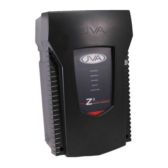
JVA ELECTRIC FENCE SYSTEMS 4. DESCRIPTION 4.1 Z-Series Exterior 4.1.2 Z18 Exterior 4.1.1 Z14/Z14R Exterior Z14 exterior Z18 exterior 4.1.4 Z11 Exterior 4.1.3 Z114 Exterior Z11 exterior Z114 exterior... -
Page 13: High Voltage Terminals
4.3 LCD Voltage Display 4.3.1 Z1X LCD Voltage Display The display on the JVA Z13/Z14/Z18 shows the voltage at the fence and return terminals. The left is the return and the right is the feed voltage. Arrows at the top of the display indicate that the energizer is in conventional mode. -
Page 14: Status Led Lights
JVA ELECTRIC FENCE SYSTEMS 4.3.2 Z114 LCD Voltage Display The display on the JVA Z114 shows the voltage at the Fence Feed and Fence Return terminals. The LCD also shows the programming option and current setting when in programming mode. This allows the programming options settings to be checked easily. -
Page 15: 4-Line Lcd Keypad (Pte0240)
4.5 4-Line LCD Keypad (PTE0240) Introduction The JVA 4-Line LCD Keypad is an integral component in the JVA Security Electric Fence product range. Providing a centralised interface between the Customer and their Perimeter Security Solution; it displays the current condition of each security device connected and can draw attention to adverse fence conditions. - Page 16 Once the cover has been removed from the base plastic, the keypad hardware will slide up to release it from the base. Installation The Keypad only requires three wire connections to JVA Energizers or Monitors. This is the +12V, GND and DATA connections on the back of the Keypad circuit board.
- Page 17 When connecting a Group of Energizers together, the +12V wire is only required between the Keypad and Energizer. The other Energizers are connected together using the GND and DAT terminals only. Keypad terminals on a JVA Single Zone Energizer Keypad Operation Note: Z-Series Energizers/Monitors have the following Default PINs...
- Page 18 JVA ELECTRIC FENCE SYSTEMS The Keypad needs to discover all of the Energizers/Monitors connected to the Keypad for it to work properly. This is best achieved after each Energizer/Monitor has been configured and wired together in a group. The display will show “Analysing” followed by the device type connected at each zone.
- Page 19 JVA ELECTRIC FENCE SYSTEMS The keypad will automatically display a new Zone Alarm or Trouble and it will remain on this page for 3 minutes. Pressing # again will advance the screen. If the Keypad beeper is sounding, any key press will silence it.
- Page 20 JVA ELECTRIC FENCE SYSTEMS Menu Function (when # key is pressed) Show Shortcuts Displays commonly used Key Sequences for reference Remember User This will ‘save’ the USER PIN entered. From now on, the Quick Arm/ PIN / Disarm buttons will not require a PIN to operate. Pressing Menu button immediately enter the Menu system as well.
- Page 21 JVA ELECTRIC FENCE SYSTEMS Event Log The Event log contains information about Alarms, Log Entry: Troubles and Arm/Disarm commands. Each event is 14:35 13/02/15 displayed on a separate page. Press the Up or Down Zone 1 key to change pages. Press # to exit the Log. The most Fence Alarm recent entry is displayed when the log is first opened.
- Page 22 JVA ELECTRIC FENCE SYSTEMS Program Device Requirements for Menu Driven Programming For this system to work effectively, all connected Energizers/Monitors need to be Mk2 protocol compliant. This version is usually found in the Black Plastic box, rather than a Silver Plastic box. Procedure The Keypad takes around 10 seconds to enter Menu Driven Programming mode. Once entered, the list of connected devices will be listed.
- Page 23 When the correct letter is displayed, either press a different Key or Pause for 2 seconds before pressing the same Key. For example: To enter the letter R, you would press Key 7 three times. To enter JVA, you would press 58882 To enter ACE, you would press 2 (pause for 2 seconds) 22233...
- Page 24 JVA ELECTRIC FENCE SYSTEMS Changing the Keypad Number options (Arrow Keys) The Keypad BAUD and Keypad ID options can be changed using the Up/Down Arrow Keys. Press # when the correct value has been selected. Pressing the * key will discard any changes and the display will show the previous option.
- Page 25 JVA ELECTRIC FENCE SYSTEMS...
- Page 26 JVA ELECTRIC FENCE SYSTEMS...
-
Page 27: Internal Beeper/Keypad Beeper
JVA ELECTRIC FENCE SYSTEMS 4.6 Internal Beeper/Keypad Beeper Depending on the Chime Mode setting, the internal beeper and keypad beeper will sound when there is a fence alarm, a gate alarm, a general alarm or a door chime. On flat battery the keypad will always beep 4 times before the energizer automatically enters low power mode to preserve the battery. -
Page 28: Programmable Options
JVA ELECTRIC FENCE SYSTEMS JVA ELECTRIC FENCE SYSTEMS 4.11 Programmable Options The Z-Series of security energizers have many programmable options. These are also known as Setup Parameters. To alter these options a keypad must be used. Please refer to Section 4.5 Programming options in detail. Each parameter has a factory set default. -
Page 29: Installation
JVA ELECTRIC FENCE SYSTEMS JVA ELECTRIC FENCE SYSTEMS 5. INSTALLATION It is recommended that all installations are performed by qualified technicians. 5.1 Installation Steps Read the entire manual first! Design and build the fence. (Beyond the scope of this manual.) Ask your distributor for help if required. Decide where the Z-Series security energizer is to be mounted. If on an external wall it should be housed within an equipment box and definitely not in direct sunlight. -
Page 30: Example Fence Wiring Diagrams
JVA ELECTRIC FENCE SYSTEMS 5.2 Example Fence Wiring Diagrams 5.2.1 Z13/Z14/Z14R/Z18 Energizer Fence Wiring Energizer Earth Z1X Energizer configured for conventional fence operation... - Page 31 JVA ELECTRIC FENCE SYSTEMS Energizer Earth Z1X Energizer configured for bi-polar operation...
-
Page 32: Operation
JVA ELECTRIC FENCE SYSTEMS 6. OPERATION 6.1 Arm/Disarm Control The Z-Series of security energizers can be armed or disarmed by the Control Input 1 or via a keypad. The keypad also allows instant audiovisual indication of the state of the energizer and therefore the fence it is powering. -
Page 33: To Silence The Alarm
JVA ELECTRIC FENCE SYSTEMS 6.3 To Silence the Alarm Enter your PIN and press #. This will silence the alarm but not disarm the system; the armed light will still be on. The system will be ready for the next alarm. The Zone lights on the keypad will flash to show where the breach occurred. The siren and strobe are ready to respond again if triggered. -
Page 34: Technical Information
JVA ELECTRIC FENCE SYSTEMS 7. TECHNICAL INFORMATION 7.1 Low Voltage Terminals The low voltage terminals have over voltage protection to protect the circuit board from excessively high voltages such as power surges or incorrect installation. 7.1.1 Z13/Z14/Z114 Low Voltage Terminals Z13/Z14/Z114 Low Voltage Terminals Z14 Low Voltage Terminal Descriptions... - Page 35 JVA ELECTRIC FENCE SYSTEMS 7.1.2 Z14R/Z18 Low Voltage Terminals Z14R/Z18 Low Voltage Terminals Z14R/Z18 Low Voltage Terminal Descriptions Label Type Description 2 Way Energizer control input (dry contact). Defaults to normally open. Can be used for a remote switch or a radio receiver. The receiver may be powered from the keypad +12V terminal.
-
Page 36: Power Options
JVA ELECTRIC FENCE SYSTEMS 7.2 Power Options The Z-Series of security energizers have 2 sources of power, 16Vac and 12VDC (Battery). The energizers cannot operate without a battery. Under no circumstances should a Z-Series security energizer rely on the keypad bus for power. -
Page 37: Jumpers
JVA ELECTRIC FENCE SYSTEMS continues to fall, the energizer will eventually stop. Once mains power has been restored and the battery has recovered, the energizer will re-arm itself automatically after 4 warning beeps. A tamper or a PCB fault will disarm the Energizer. If an error disarms the Energizer, the General Alarm and Fence Alarm will be activated. -
Page 38: Multiple Keypads
JVA ELECTRIC FENCE SYSTEMS JVA ELECTRIC FENCE SYSTEMS 7.8 Multiple Keypads All Z-Series energizers have support for up to three keypads provided the Energizers firmware version is 7v66 and above. If more than one keypad is desired the second and subsequent keypads will need to have ID’s set to 4 to 7. The first keypad can be left at the default ID 1. ID 2 and 3 should not be used. ID 2 is reserved for a PC running Perimeter Patrol. -
Page 39: Sector Setup Tests And Adjustment
JVA ELECTRIC FENCE SYSTEMS JVA ELECTRIC FENCE SYSTEMS 8. SECTOR SETUP TESTS AND ADJUSTMENT 8.1 Introduction With a Single Zone system there are three considerations for the electric fence monitor voltage level: 1. The monitor should trigger the alarm if one of the live wires is shorted to ground. -
Page 40: Fault Condition Tests
JVA ELECTRIC FENCE SYSTEMS JVA ELECTRIC FENCE SYSTEMS 8.3 Fault Condition Tests 1. To simulate a break, disconnect a joint(s) in the live wires at some convenient point on the fence, making sure that the wires do not short to ground or between +ve and -ve wires. 2. Check that the energizer fence alarm activates. If not check the voltage (using an electric fence voltmeter) at the inputs to the monitor. -
Page 41: Legal And Safety Requirements For Electric Fences
30m along the fence line in urban areas. • Insert the earth stakes at least 2m away from any mains earth electrodes. • Do not attach your earth wires to any electrodes connected to a mains supply. • Avoid running an electric fence parallel to or under mains power or telephone lines. • When in doubt check with your local authority. • For any further information regarding the legalities and safety requirements for electric fencing in your area, contact your local JVA agent or supplier. -
Page 42: Appendix A: Group Simultaneous Pulse Feature
JVA ELECTRIC FENCE SYSTEMS APPENDIX A: Group Simultaneous Pulse Feature Group Simultaneous Pulse Feature In some Industrial Installations it may be preferable to provide the ability to link multiple Energizers into a group. When linked the individual Z-Series Energizers become a “Group”. Members of a group have simultaneous high voltage output pulses and act as is they are one energizer with multiple outputs. - Page 43 JVA ELECTRIC FENCE SYSTEMS For all Energizers that will be part of a group, the procedure is as follows: 1. Make sure the key switch is turned off and IN1 isn’t shorted (note that the Z14R does not have a key switch). Connect the battery. On the keypad, enter [Installer’s code] [*] [0] [#].
- Page 44 JVA ELECTRIC FENCE SYSTEMS Notes: Members of a group can be individually switched on and off; even the master can be turned off via input or key switch (note that the Z14R does not have a key switch). For Arming and Disarming INDIVIDUAL Zones, refer to page 21. A slave will generate a General alarm if the keypad bus is broken between it and the group master. After programming the Keypad may be disconnected, it is not required for group operation.
- Page 45 JVA ELECTRIC FENCE SYSTEMS Perimeter Patrol Software The JVA Perimeter Patrol software package enables one or more energizers to be monitored and controlled from a PC. This package can be used for a standalone system where the owner is interested in a visual representation of an electrified enclosure (mimic screen) and the ease of operation that a Windows compatible GUI application can provide.
- Page 46 JVA ELECTRIC FENCE SYSTEMS Group Mode Limitations Using Category 5 Cable: • For best results, the Master should be connected closest to the control/monitoring unit (Keypad, computer or LCD display). Note that the keypad can only tolerate 4.5 Ohm resistance on the GND wire from the Master to be able to control more than 15 Energizers in the system. When using CAT 5 cable, 2 or more wires can be shorted together to reduce the cable resistance.
-
Page 47: Appendix B: Pulse Synchronization
JVA ELECTRIC FENCE SYSTEMS APPENDIX B: Pulse Synchronization Introduction The synchronization of electric fence energizers powering zones of a multi-zone security electric fence is a safety requirement to prevent anyone (personnel or intruders) from receiving a potentially lethal shock. The danger arises when multiple zones powered by different energizers intersect which is often the case in security installations. - Page 48 JVA ELECTRIC FENCE SYSTEMS JVA ELECTRIC FENCE SYSTEMS Section 5.2 and 5.3 of ASNZS3014 states that: 5.2 Use of one energizer An electric fence shall not be supplied from two separate independently timed energizers or from independently timed fence circuits of the same energizer.
-
Page 49: Warranty
Whilst every effort has been made to check that the information contained is accurate, JVA Technologies Pty Ltd will not be liable to loss or damage resulting from construction, operation or failure of any installation or system. Installation of security electric fences should be made by trained professionals with regard to the relevant local standards and workplace health and safety requirements. - Page 50 JVA ELECTRIC FENCE SYSTEMS NOTES...
- Page 51 JVA dealer. SA Tel. No.: 0861 782 349. For service or repairs: If a service or repair is required, please package and label your energizer carefully and return it to your local JVA Service Centre. For warranty repairs: Include proof of purchase, e.g. invoice.
- Page 52 JVA ELECTRIC FENCE SYSTEMS JVA products are designed by JVA Technologies, Queensland, Australia and distributed to: CARIBBEAN CENTRAL AMERICA AFRICA AUSTRALIA CENTRAL ASIA INDIA LATINO AMERICA EUROPE NEW ZEALAND PHILIPPINES PAKISTAN MEXICO RUSSIA SOUTH EAST ASIA SRI LANKA UNITED KINGDOM...
Need help?
Do you have a question about the Z Series and is the answer not in the manual?
Questions and answers