HPE ProLiant BL460c Gen10 User Manual
Hide thumbs
Also See for ProLiant BL460c Gen10:
- User manual (101 pages) ,
- Maintenance and service manual (111 pages)
Table of Contents
Advertisement
HPE ProLiant BL460c Gen10 Server Blade
User Guide
Abstract
This document is for the person who installs, administers, and troubleshoots server blades.
Hewlett Packard Enterprise assumes you are qualified in the servicing of computer equipment and
trained in recognizing hazards in products with hazardous energy levels.
Part Number: 876833-001
Published: July 2017
Edition: 1
Advertisement
Table of Contents

Related Manuals for HPE ProLiant BL460c Gen10


Summary of Contents for HPE ProLiant BL460c Gen10
-
Page 1: User Guide
HPE ProLiant BL460c Gen10 Server Blade User Guide Abstract This document is for the person who installs, administers, and troubleshoots server blades. Hewlett Packard Enterprise assumes you are qualified in the servicing of computer equipment and trained in recognizing hazards in products with hazardous energy levels. - Page 2 © Copyright 2014, 2017 Hewlett Packard Enterprise Development LP Notices © Copyright Hewlett Packard Enterprise Development LP The information contained herein is subject to change without notice. The only warranties for Hewlett Packard Enterprise products and services are set forth in the express warranty statements accompanying such products and services.
-
Page 3: Table Of Contents
Mezzanine connector definitions.................... 14 DIMM slot locations........................ 14 SUV cable connectors........................14 Setup......................16 Overview............................16 Installing an HPE BladeSystem c-Class enclosure................16 Preparing the enclosure......................16 Preparing the Server Blade for installation................16 Installing server blade options......................17 Installing interconnect modules......................17 Interconnect bay numbering and device mapping.............. - Page 4 TPM 2.0 location........................50 HPE Trusted Platform Module 2.0 Guidelines................ 51 Disabling Chipset-TPM......................51 Installing and enabling the HPE TPM 2.0 Gen10 Kit.............. 52 Installing the Trusted Platform Module board.............. 52 Enabling the Trusted Platform Module.................54 Retaining the recovery key/password................55 Cabling......................56...
- Page 5 HPE Insight Diagnostics survey functionality...............63 Erase Utility..........................63 Scripting Toolkit for Windows and Linux.................... 64 Service Pack for ProLiant........................64 HP Smart Update Manager....................64 UEFI System Utilities.........................64 Using UEFI System Utilities....................65 Flexible boot control........................65 Restoring and customizing configuration settings..............65 Secure Boot configuration......................
- Page 6 Customer self repair.......................... 76 Remote support..........................77 Warranty information......................... 77 Regulatory information........................78 Documentation feedback........................78 Contents...
-
Page 7: Component Identification
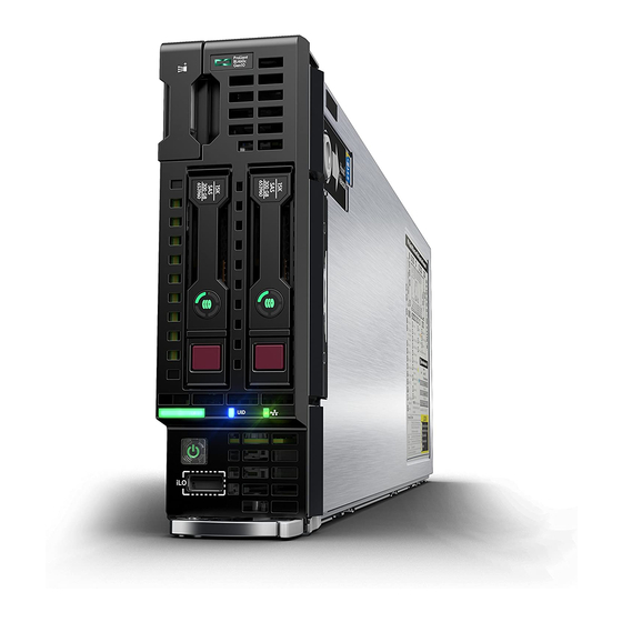
Component identification Front panel components Item Description Serial label pull tab HPE c-Class Blade SUV connector* (behind the serial label pull tab) Drive bay 2 Drive bay 1 Server blade release lever Server blade release latch iLO Debug USB port *The SUV connector and the c-Class Blade SUV Cable are used for some Server Blade configuration and diagnostic procedures. -
Page 8: Front Panel Leds And Buttons
Front panel LEDs and buttons Item Description Status NIC status LED Solid green = Link to network Flashing green (1 flash per second) = Network active Off = No network activity UID LED Solid blue = Activated Flashing blue: • 1 flash per second = Remote management or firmware upgrade in progress... -
Page 9: Front Panel Led Power Fault Codes
2 flashes Memory 3 flashes Riser board PCIe slots 4 flashes FlexibleLOM 5 flashes Removable HPE Flexible Smart Array controller/Smart SAS HBA 6 flashes controller System board PCIe slots 7 flashes Power backplane or storage backplane 8 flashes Power supply... -
Page 10: Drive Numbering
• Product serial number • iLO 5 information • QR code that points to mobile-friendly documentation Drive numbering Item Description Drive bay 1 Drive bay 2 Hot-plug drive LED definitions Item LED Status Definition Locate Solid blue The drive is being identified by a host application. Flashing blue The drive carrier firmware is being updated or requires an update. -
Page 11: Nvme Ssd Components
Item LED Status Definition Flashing amber/ The drive is a member of one or more logical drives and predicts the green drive will fail. Flashing amber The drive is not configured and predicts the drive will fail. Solid amber The drive has failed. The drive is not configured by a RAID controller. -
Page 12: System Board Components
Item Component Status Definition Power button — Momentary press to request drive removal from PCIe bus and ejection. Drive removal request can be denied by operating system. Do Not Remove button — Releases the release lever for removal and insertion. Upon NVMe SSD insertion, an LED initiation sequence will be visible - lighting each LED in the carrier in sequence from left to right. -
Page 13: System Maintenance Switch
Item Description SAS/SATA controller or NVMe pass-through board connector Delete from CAD SAS/SATA or NVMe backplane Internal USB 3.0 connector Direct-connect SATA connector TPM connector MicroSD card slot Smart Storage Battery connector System maintenance switch System maintenance switch Position Default Function Off = iLO security is enabled. -
Page 14: Mezzanine Connector Definitions
CAUTION: Clearing CMOS, NVRAM, or both deletes configuration information. Be sure to configure the Server Blade properly to prevent data loss. Mezzanine connector definitions Item PCIe Mezzanine connector 1 x16, Type A mezzanine card only Mezzanine connector 2 x16, Type A or B mezzanine card NOTE: When installing a mezzanine option on mezzanine connector 2, processor 2 must be installed. - Page 15 Item Connector Description Serial For trained personnel to connect a null modem serial cable and perform advanced diagnostic procedures For connecting up to two USB 2.0 devices Video For connecting a video monitor The USB connectors on the SUV cable do not support devices that require greater than a 500mA power source.
-
Page 16: Setup
Setup IMPORTANT: The HPE Synergy Gen10 compute module installation involves a minimum upgrade requirement for component compatibility purposes. To ensure proper system functionality, you must update your system to Release Set Version 3.00.20170707 (or later) before installing and operating your compute module. -
Page 17: Installing Server Blade Options
For Server Blade options installation information, see "Hardware options installation." Installing interconnect modules For specific steps to install interconnect modules, see the documentation that ships with the interconnect module. Interconnect bay numbering and device mapping • HPE BladeSystem c7000 Enclosure Installing server blade options... - Page 18 Mezzanine 2 5 and 6 Mezzanine 2 7 and 8 For detailed port mapping information, see the BladeSystem enclosure installation poster or the BladeSystem enclosure setup and installation guide on the Hewlett Packard Enterprise website. • HPE BladeSystem c3000 Enclosure Setup...
-
Page 19: Connecting To The Network
Server blade signal Interconnect bay Interconnect bay label Notes number FlexibleLOM — Mezzanine 1 Four-port cards connect to bay 2. Mezzanine 2 3 and 4 ◦ Four-port cards ◦ Ports 1 and 3 connect to bay 3. ◦ Ports 2 and 4 connect to bay 4. - Page 20 CAUTION: Failure to install the divider in a quadrant when installing half-height blades can result in damage to the connectors on the server blades. For the best possible BladeSystem and Virtual Connect experience, and to prevent a future reboot, Hewlett Packard Enterprise requires updating the Onboard Administrator and Virtual Connect to the correct version before installing a ProLiant Gen10 Server Blade.
-
Page 21: Completing The Configuration
Completing the configuration To complete the Server Blade and BladeSystem configuration, see the overview card that ships with the enclosure. Completing the configuration... -
Page 22: Operations
For more information about the , see the setup and installation guide on the Hewlett Packard Enterprise website. For more information about iLO 5 , see "HPE iLO." Power down the Server Blade Before powering down the Server Blade for any upgrade or maintenance procedures, perform a backup of critical server data and programs. -
Page 23: Remove The Server Blade
◦ For a controlled shutdown, select Momentary Press. ◦ For an emergency shutdown, select Press and Hold. Before proceeding, verify that the Server Blade is in standby mode by observing that the system power LED is amber. Remove the Server Blade 1. - Page 24 For more information on this and other specific firmware and driver requirements, as well as the latest firmware and driver versions, download the SPP on the Hewlett Packard Enterprise website. Procedure 1. Remove the device bay blank. Retain the blank for future use. 2.
-
Page 25: Remove The Access Panel
Remove the access panel To remove the component: Procedure 1. Power down the Server Blade . 2. Remove the Server Blade . 3. Place the Server Blade on a flat, level work surface. 4. Press the access panel release button. 5. -
Page 26: Remove The Dimm Baffles
Remove the DIMM baffles The server contains two DIMM baffles. Procedure 1. Power down the Server Blade . 2. Remove the Server Blade . 3. Place the Server Blade on a flat, level work surface. 4. Remove the access panel. 5. -
Page 27: Install The Dimm Baffles
Install the DIMM baffles The server contains two DIMM baffles. Procedure 1. Place the Server Blade on a flat, level work surface. 2. Remove the access panel. 3. Install the DIMM baffle. • DIMM baffle (right side) • DIMM baffle (left side) Install the DIMM baffles... -
Page 28: Remove The Direct Connect Sata Cable
4. Install the access panel. 5. Install the server blade. 6. Power up the Server Blade . Remove the direct connect SATA cable The server uses SATA drives that can be removed if necessary. Procedure 1. Power down the Server Blade . 2. -
Page 29: Install The Direct Connect Sata Cable
Install the direct connect SATA cable The server uses removable direct connect SATA cables. Procedure 1. Power down the Server Blade . 2. Remove the Server Blade . 3. Place the Server Blade on a flat, level work surface. 4. Remove the access panel. 5. -
Page 30: Remove The Mezzanine Assembly
Remove the mezzanine assembly The server uses a removable mezzanine assembly. Procedure 1. Power down the Server Blade . 2. Remove the Server Blade . 3. Place the Server Blade on a flat, level work surface. 4. Remove the access panel. 5. -
Page 31: Install The Flexiblelom
Install the FlexibleLOM The server has a removable FlexibleLOM. Procedure Power down the Server Blade . Remove the Server Blade . Place the Server Blade on a flat, level work surface. Remove the access panel. Remove the mezzanine assembly. Install the FlexibleLOM. Install the mezzanine assembly. -
Page 32: Remove The Storage Controller/Nvme Pass-Through Board
Remove the storage controller/NVMe pass-through board 1. Back up all Server Blade data. 2. Power down the Server Blade . 3. Remove the Server Blade . 4. Place the Server Blade on a flat, level work surface. 5. Remove the access panel. 6. -
Page 33: Remove A Drive
Remove the Server Blade . Place the Server Blade on a flat, level work surface. Remove the access panel. Prepare the storage controller/NVMe pass-through board for installation. Align the storage controller/NVMe pass-through board with the alignment pins and lower it into Server Blade. -
Page 34: Installing A Hot-Plug Drive
1. Prepare the drive. 2. Install the drive. 3. Determine the status of the drive from the drive LED definitions. To configure arrays, see the HPE Smart Storage Administrator User Guide on the Hewlett Packard Enterprise website. Remove the front panel/drive cage assembly The server has one drive cage assembly. -
Page 35: Install The Front Panel/Drive Cage Assembly
Procedure 1. Power down the Server Blade . 2. Remove the Server Blade . 3. Place the Server Blade on a flat, level work surface. 4. Remove the access panel. 5. Do one of the following: • Remove the storage controller/NVMe pass-through board. •... - Page 36 2. Install all DIMM baffles. 3. Do one of the following: • Install the storage controller/NVMe pass-through board. • Install the direct connect SATA cable. 4. Install the access panel. 5. Install the server blade. 6. Power up the Server Blade . Operations...
-
Page 37: Hardware Options Installation
Hardware options installation Introduction If more than one option is being installed, read the installation instructions for all the hardware options and identify similar steps to streamline the installation process. WARNING: To reduce the risk of personal injury from hot surfaces, allow the drives and the internal system components to cool before touching them. -
Page 38: Nvme Ssd Option
4. Determine the status of the drive from the drive LED definitions. NVMe SSD option The server can use NVMe SSD's that are hot-pluggable. CAUTION: To prevent improper cooling and thermal damage, do not operate the Server Blade or the enclosure unless all drive and device bays are populated with either a component or a blank. -
Page 39: Storage Controller/Nvme Pass-Through Board Options
4. Determine the status of the drive from the LEDs. Storage controller/NVMe pass-through board options To install the component: Procedure Back up all Server Blade data. Power down the Server Blade . Remove the Server Blade . Place the Server Blade on a flat, level work surface. Remove the access panel. -
Page 40: Smart Storage Battery Option
Install the access panel. 10. Install the Server Blade . 11. Power up the Server Blade . Smart Storage Battery option To install the component: Procedure Power down the Server Blade . Remove the Server Blade . Place the Server Blade on a flat, level work surface. Remove the access panel. - Page 41 Route the cable on the DIMM baffle. 10. Align and install the DIMM baffle. 11. Press down on the cable connector to fully seat the Smart Storage Battery cable connector to the system board. Hardware options installation...
-
Page 42: Mezzanine Card Option
12. If removed, install the direct connect SATA cable. 13. If removed, install the internal USB drive. To locate the internal USB connector, see "System board components." 14. Install the access panel. 15. Install the Server Blade . 16. Power up the Server Blade . Mezzanine card option Optional mezzanine cards are classified as Type A mezzanine cards and Type B mezzanine cards. - Page 43 Align the mezzanine card with the guide pins on the mezzanine assembly. Install the mezzanine card in the mezzanine assembly, and then tighten the mezzanine card screws to secure the card to the mezzanine assembly. Hardware options installation...
-
Page 44: M.2 Enablement Option
Align the mezzanine assembly with the guide pins on the system board, and then install the mezzanine assembly on the system board. Press down firmly on the mezzanine assembly handles, and then close the mezzanine assembly latch. 10. Install the access panel. 11. -
Page 45: Memory Options
DIMM population information For specific DIMM population information, see the DIMM population guidelines on the Hewlett Packard Enterprise website (http://www.hpe.com/docs/memory-population-rules). HPE Smart Memory speed information For more information about memory speed information, see the Hewlett Packard Enterprise website (https:// www.hpe.com/docs/memory-speed-table). - Page 46 8GB 1Rx4 DDR4-2666P-R 8GB 1Rx4 DDR4-2666P-R Item Description Definition Capacity 8 GB 16 GB 32 GB 64 GB 128 GB Rank 1R = Single rank 2R = Dual rank 4R = Quad rank 8R = Octal rank Data width on DRAM x4 = 4-bit x8 = 8-bit x16 = 16-bit...
-
Page 47: Installing A Dimm
For more information about product features, specifications, options, configurations, and compatibility, see the product QuickSpecs on the Hewlett Packard Enterprise website (http://www.hpe.com/info/qs). Installing a DIMM The server supports up to 24 DIMMs. Prerequisites Before installing this option, be sure you have the following:... -
Page 48: Installing The Processor Heatsink
Update the system ROM. Locate and download the latest ROM version from the Hewlett Packard Enterprise website at http:// www.hpe.com/support. Follow the instructions on the website to update the system ROM. Power down the Server Blade. Remove the Server Blade. - Page 49 Align the processor heatsink assembly with the alignment pins and gently lower it down until it sits evenly on the socket. The heatsink alignment pins are keyed. The processor will only install one way. A standard heatsink is shown. Your heatsink might look different. Secure the heatsink using a T-15 screwdriver.
-
Page 50: Hpe Trusted Platform Module 2.0 Gen10 Option
TPM including keys will be erased. IMPORTANT: In UEFI Boot Mode, the HPE TPM 2.0 Gen10 Kit can be configured to operate as TPM 2.0 (default) or TPM 1.2 on a supported Server Blade. In Legacy Boot Mode, the configuration can be changed between TPM 1.2 and TPM 2.0, but only TPM 1.2 operation is supported. -
Page 51: Hpe Trusted Platform Module 2.0 Guidelines
Chipset-TPM is not available after the HPE TPM 2.0 Gen10 Kit is installed and configured in System Utilities. Do not install the HPE TPM 2.0 Gen10 Kit if Chipset-TPM is enabled and the operating system is using Chipset-TPM features. Otherwise, the OS may go into recovery mode, data loss can occur, or both. -
Page 52: Installing And Enabling The Hpe Tpm 2.0 Gen10 Kit
Before installing and enabling the HPE TPM 2.0 Gen10 Kit, verify that Chipset-TPM is disabled. For more information on disabling Chipset-TPM, see the UEFI System Utilities User Guide for HPE ProLiant Gen10 Servers and HPE Synergy on the Hewlett Packard Enterprise website. - Page 53 CAUTION: The TPM is keyed to install only in the orientation shown. Any attempt to install the TPM in a different orientation might result in damage to the TPM or system board. 2. Align the TPM board with the key on the connector, and then install the TPM board. To seat the board, press the TPM board firmly into the connector.
-
Page 54: Enabling The Trusted Platform Module
a. Install the Server Blade in the rack, if necessary. b. Install the Server Blade in the enclosure. 4. Power up the Server Blade. a. Connect the power cords (rack and tower servers). b. Press the Power On/Standby button. Enabling the Trusted Platform Module When enabling the Trusted Platform module, observe the following guidelines: •... -
Page 55: Retaining The Recovery Key/Password
5. Press the F10 key to save your selection. 6. When prompted to save the change in System Utilities, do one of the following: • If in graphical mode, click Yes. • If in text mode, press the Y key. 7. -
Page 56: Cabling
Cabling configurations and requirements vary depending on the product and installed options. For more information about product features, specifications, options, configurations, and compatibility, see the product QuickSpecs on the website . HPE Smart Storage Battery cabling Direct connect SATA cabling Cabling... -
Page 57: Using The Hpe C-Class Blade Suv Cable
Using the HPE c-Class Blade SUV Cable The c-Class Blade SUV Cable enables the user to perform Server Blade administration, configuration, and diagnostic procedures by connecting video and USB devices directly to the Server Blade. For SUV cable connectors, see "SUV cable connectors."... -
Page 58: Accessing Local Media Devices
Item Description Monitor USB mouse USB keyboard c-Class Blade SUV Cable Accessing local media devices Use the following configuration when configuring a Server Blade or loading software updates and patches from a USB CD/DVD-ROM. Use a USB hub when connecting a USB CD-ROM drive to the Server Blade. The USB connectors on the SUV cable do not support devices that require greater than a 500mA power source. -
Page 59: Troubleshooting
• Error Message Guide for HPE ProLiant Gen10 servers and HPE Synergy provides a list of error messages and information to assist with interpreting and resolving error messages. •... -
Page 60: Software And Configuration Utilities
QuickSpecs on the Hewlett Packard Enterprise website (http://www.hpe.com/info/qs). HPE iLO iLO is a remote server management processor embedded on the system boards of HPE ProLiant and Synergy servers. iLO enables the monitoring and controlling of servers from remote locations. HPE iLO management is a powerful tool that provides multiple ways to configure, update, monitor, and repair servers remotely. -
Page 61: Ilo Restful Api Support
Intelligent Provisioning User Guide on the Hewlett Packard Enterprise website iLO RESTful API support HPE iLO 4 firmware version 2.00 and later includes the iLO RESTful API. The iLO RESTful API is a management interface that server management tools can use to perform configuration, inventory, and monitoring of the ProLiant server via iLO. -
Page 62: Hpe Insight Remote Support
For more information, see the product documentation on the Hewlett Packard Enterprise website. Insight Online HPE Insight Online is a capability of the Support Center portal. Combined with Insight Remote Support central connect or Insight Online direct connect, it automatically aggregates device health, asset, and support information with contract and warranty information, and then secures it in a single, personalized dashboard that is viewable from anywhere at any time. -
Page 63: Intelligent Provisioning
Diagnostics Online Edition is also available in the SPP. HPE Insight Diagnostics survey functionality HPE Insight Diagnostics provides survey functionality that gathers critical hardware and software information on ProLiant Server Blades. This functionality supports operating systems that are supported by the Server Blade. For operating systems supported by the Server Blade, see the Hewlett Packard Enterprise website. -
Page 64: Scripting Toolkit For Windows And Linux
Use the Erase Utility to erase drives and Active Health System logs, and to reset UEFI System Utilities settings. Run the Erase Utility if you must erase the system for the following reasons: • You want to install a new operating system on a Server Blade with an existing operating system. •... -
Page 65: Using Uefi System Utilities
• Launching other pre-boot environments such as the Embedded UEFI Shell and Intelligent Provisioning For more information on the UEFI System Utilities, see the UEFI System Utilities User Guide for HPE ProLiant Gen10 Servers on the Hewlett Packard Enterprise website. -
Page 66: Secure Boot Configuration
Embedded Diagnostics option can run comprehensive diagnostics of the server hardware, including processors, memory, drives, and other server components. For more information on the Embedded Diagnostics option, see the HPE UEFI System Utilities User Guide for HPE ProLiant Gen10 Servers on the Hewlett Packard Enterprise website. -
Page 67: Re-Entering The Server Serial Number And Product Id
ProLiant Gen8 servers, HPE SSA replaces ACU with an enhanced GUI and additional configuration features. The HPE SSA exists in three interface formats: the HPE SSA GUI, the HPE SSA CLI, and HPE SSA Scripting. Although all formats provide support for configuration tasks, some of the advanced tasks are available in only one format. -
Page 68: Automatic Server Recovery
The pre-OS behavior of the USB ports is configurable in the UEFI System Utilities, so that the user can change the default operation of the USB ports. For more information, see the HPE UEFI System Utilities User Guide for HPE ProLiant Gen9 Servers on the Hewlett Packard Enterprise website. -
Page 69: Safety And Security Benefits
SPP, see the Hewlett Packard Enterprise website. To locate the drivers for a particular server, go to the Hewlett Packard Enterprise Support Center website. Under Select your HPE product, enter the product name or number and click Go. Software and firmware Software and firmware should be updated before using the server for the first time, unless any installed software or components require an older version. -
Page 70: Operating Systems And Virtualization Software Support For Proliant Servers
For information about specific versions of a supported operating system, see the Hewlett Packard Enterprise website. HPE Technology Service Portfolio Connect to Hewlett Packard Enterprise for assistance on the journey to the new style of IT. The Hewlett Packard Enterprise Technology Services delivers confidence and reduces risk to help you realize agility and stability in your IT infrastructure. -
Page 71: System Battery Replacement
System battery replacement If the Server Blade no longer automatically displays the correct date and time, then replace the battery that provides power to the real-time clock. Under normal use, battery life is 5 to 10 years. WARNING: The computer contains an internal lithium manganese dioxide, a vanadium pentoxide, or an alkaline battery pack. -
Page 72: Electrostatic Discharge
Electrostatic discharge Preventing electrostatic discharge To prevent damaging the system, be aware of the precautions you must follow when setting up the system or handling parts. A discharge of static electricity from a finger or other conductor may damage system boards or other static-sensitive devices. -
Page 73: Specifications
Specifications Environmental specifications Specification Value Temperature range* — Operating 10°C to 35°C (50°F to 95°F) Non-operating -30°C to 60°C (-22°F to 140°F) Relative humidity (noncondensing)** — Operating 10% to 90% @ 28°C (82.4°F) Non-operating 5% to 95% @ 38.7°C (101.7°F) Altitude†... -
Page 74: Safety, Warranty, And Regulatory Information
For important safety, environmental, and regulatory information, see Safety and Compliance Information for Server, Storage, Power, Networking, and Rack Products, available at the Hewlett Packard Enterprise website (http://www.hpe.com/support/Safety-Compliance-EnterpriseProducts). Warranty information HPE ProLiant and x86 Servers and Options HPE Enterprise Servers HPE Storage Products HPE Networking Products... -
Page 75: Turkey Rohs Material Content Declaration
• Belarus: • Kazakhstan: Manufacturing date: The manufacturing date is defined by the serial number. CCSYWWZZZZ (serial number format for this product) Valid date formats include: • YWW, where Y indicates the year counting from within each new decade, with 2000 as the starting point; for example, 238: 2 for 2002 and 38 for the week of September 9. -
Page 76: Support And Other Resources
IMPORTANT: Access to some updates might require product entitlement when accessed through the Hewlett Packard Enterprise Support Center. You must have an HPE Passport set up with relevant entitlements. Customer self repair Hewlett Packard Enterprise customer self repair (CSR) programs allow you to repair your product. If a CSR part needs to be replaced, it will be shipped directly to you so that you can install it at your convenience. -
Page 77: Remote Support
Remote support and Proactive Care information HPE Get Connected www.hpe.com/services/getconnected HPE Proactive Care services www.hpe.com/services/proactivecare HPE Proactive Care service: Supported products list www.hpe.com/services/proactivecaresupportedproducts HPE Proactive Care advanced service: Supported products list www.hpe.com/services/proactivecareadvancedsupportedproducts Proactive Care customer information Proactive Care central www.hpe.com/services/proactivecarecentral Proactive Care service activation www.hpe.com/services/proactivecarecentralgetstarted... -
Page 78: Regulatory Information
Documentation Feedback (docsfeedback@hpe.com). When submitting your feedback, include the document title, part number, edition, and publication date located on the front cover of the document. For online help content, include the product name, product version, help edition, and publication date located on the legal notices page.
Need help?
Do you have a question about the ProLiant BL460c Gen10 and is the answer not in the manual?
Questions and answers