Table of Contents
Advertisement
Quick Links
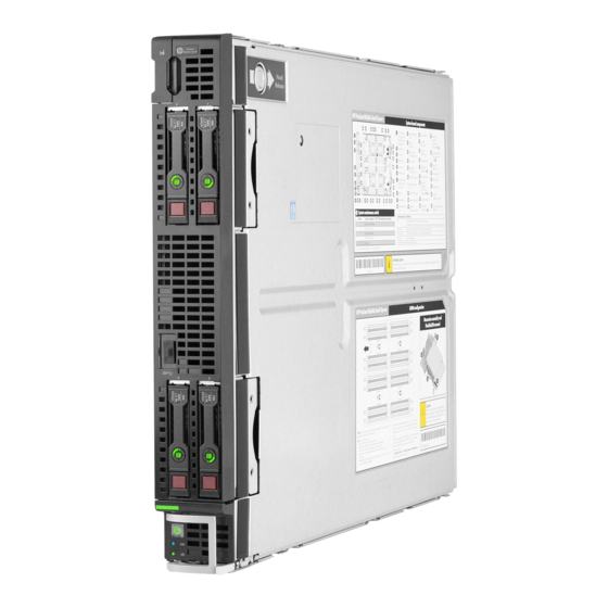
HPE ProLiant BL660c Gen9 Server
Blade
User Guide
Abstract
This document is for the person who installs, administers, and troubleshoots servers and storage systems. Hewlett Packard Enterprise
assumes you are qualified in the servicing of computer equipment and trained in recognizing hazards in products with hazardous energy
levels.
Part Number: 798293-003
March 2017
Edition: 4
Advertisement
Table of Contents

Subscribe to Our Youtube Channel
Related Manuals for HPE ProLiant BL660c Gen9


Summary of Contents for HPE ProLiant BL660c Gen9
-
Page 1: User Guide
HPE ProLiant BL660c Gen9 Server Blade User Guide Abstract This document is for the person who installs, administers, and troubleshoots servers and storage systems. Hewlett Packard Enterprise assumes you are qualified in the servicing of computer equipment and trained in recognizing hazards in products with hazardous energy levels. - Page 2 © Copyright 2015, 2017 Hewlett Packard Enterprise Development LP The information contained herein is subject to change without notice. The only warranties for Hewlett Packard Enterprise products and services are set forth in the express warranty statements accompanying such products and services. Nothing herein should be construed as constituting an additional warranty.
-
Page 3: Table Of Contents
Install the front panel/drive cage assembly ......................28 Setup ..............................30 Overview ................................30 Installing an HPE BladeSystem c-Class enclosure ....................30 Preparing the enclosure ..........................30 Installing interconnect modules ..........................33 Interconnect bay numbering and device mapping ..................33 Connecting to the network ............................ - Page 4 Direct connect SATA cabling ..........................64 SAS cabling ................................65 Using the HPE c-Class Blade SUV Cable ......................65 Connecting locally to a server blade with video and USB devices ................. 66 Accessing a server blade with local KVM ....................66 Accessing local media devices ........................
- Page 5 Software and firmware..........................79 Operating System Version Support ......................79 Version control............................. 79 Operating systems and virtualization software support for ProLiant servers..........79 HPE Technology Service Portfolio ......................79 Change control and proactive notification ....................80 Troubleshooting ........................... 81 Troubleshooting resources ............................. 81 System battery replacement ........................
-
Page 6: Component Identification
Component identification Front panel components • SATA/SAS model Item Description HPE c-Class Blade SUV cable connector* (behind the serial label pull tab) Serial label pull tab SAS/SATA drive bay 1 SAS/SATA drive bay 2 External USB 3.0 connector SAS/SATA drive bay 3... -
Page 7: Front Panel Leds And Buttons
Flashing red (1 flash per second) = System critical If the health LED indicates a degraded or critical state, review the system IML or use iLO ("HPE iLO" on page 68) to review the system health status. Power On/Standby Solid green = System on... -
Page 8: Power Fault Leds
3 flashes Memory 4 flashes Riser board PCIe slots 5 flashes FlexibleLOM 6 flashes Removable HPE Flexible Smart Array controller/Smart SAS HBA controller 7 flashes System board PCIe slots 8 flashes Power backplane or storage backplane 9 flashes Power supply Serial label pull tab information The serial label pull tab is located on the front panel of the server blade. -
Page 9: Hot-Plug Drive Led Definitions
• The drives cannot be a part of a hardware RAID or a logical drive. • The Locate, Drive status, and Do not remove LEDs of the affected drives are not controlled and will retain their last configured state. HPE SmartDrives preserve the last configured state across power cycles. -
Page 10: Nvme Ssd Components
NVMe SSD components Item Component Status Definition Release lever Ejects the NVMe drive carrier from the cage. — Activity ring LED Rotating green Drive activity No drive activity Do Not Remove Solid white Drive is powered on, and configured in system. Do not remove the drive. -
Page 11: System Board Components
System board components Item Description M.2 SSD enablement board connector Smart Storage Battery connector Processor 3 DIMM slots (8) Processor 3 Storage controller/NVMe pass-through board connector Processor 1 DIMM slots (8) Processor 1 System board thumb screws (3) Enclosure connectors Mezzanine connector 1 (Type A mezzanine only) Mezzanine connector 2 (Type A or Type B mezzanine) FlexibleLOM 2 connectors (2) -
Page 12: System Maintenance Switch
System maintenance switch Position Default Function Off = iLO security is enabled. On = iLO security is disabled. Off = System configuration can be changed. On = System configuration is locked. Reserved Reserved Off = Power-on password is enabled. On = Power-on password is disabled. Off = No function. -
Page 13: Dimm Slot Locations
DIMM slots are numbered sequentially (1 through 8) for each processor. The supported AMP modes use the alpha assignments for population order, and the slot numbers designate the DIMM slot ID for spare replacement. HPE c-Class Blade SUV Cable Item Connector... -
Page 14: Operations
For more information about the Onboard Administrator, see the enclosure setup and installation guide on the Hewlett Packard Enterprise website (http://www.hpe.com/support/oa). For more information about iLO, see "HPE iLO (on page 68)." Power down the server blade Before powering down the server blade for any upgrade or maintenance procedures, perform a backup of critical server data and programs. -
Page 15: Remove The Server Blade
Select the Enclosure Information tab. In the Device Bays item, select the Overall checkbox. From the Virtual Power menu, initiate a shutdown of applications and the OS: — For a controlled shutdown, select Momentary Press. — For an emergency shutdown, select Press and Hold. Before proceeding, verify the server blade is in standby mode by observing that the system power LED is amber. -
Page 16: Install The Access Panel
CAUTION: Do not operate the enclosure for long periods with the access panel open or removed. Operating the enclosure in this manner results in improper airflow and improper cooling that can lead to thermal damage. To remove the component: Power down the server blade (on page 14). Remove the server blade (on page 15). -
Page 17: Remove A Drive
Remove a drive Back up all server blade data on the drive. Remove the drive. Remove an NVMe drive CAUTION: Do not remove an NVMe SSD from the drive bay while the Do Not Remove button LED is flashing. The Do Not Remove button LED flashes to indicate the device is still in use. -
Page 18: Remove The Right Dimm Baffles
The server blade contains three DIMM baffles. Remove the right DIMM baffles Back up all server blade data. Power down the server blade (on page 14). Remove the server blade (on page 15). Remove the access panel (on page 15). If installed, remove the internal USB devices. -
Page 19: Remove The Left Dimm Baffle
Lift up the center DIMM baffle. iii. Remove the left DIMM baffle Back up all server blade data. Power down the server blade (on page 14). Remove the server blade (on page 15). Remove the access panel (on page 15). Disconnect the Smart storage battery connector. -
Page 20: Install The Right Dimm Baffle
CAUTION: To avoid damage to the server blade and the enclosure, install all DIMM baffles in the proper location after adding or replacing DIMMs. DIMM baffles that are missing or installed incorrectly can compromise server blade and enclosure cooling. The server blade contains three DIMM baffles. Install the right DIMM baffle Install the right DIMM baffle. -
Page 21: Install The Left Dimm Baffle
Power up the server blade (on page 14). Install the left DIMM baffle Install the left DIMM baffle. If removed, install the Smart Storage battery ("HPE Smart Storage Battery option" on page 43). If removed, connect the Direct connect SATA cables ("Install the direct connect SATA cable"... -
Page 22: Remove The Direct Connect Sata Cable
Install the access panel (on page 16). Install the server blade ("Installing a server blade" on page 36). Power up the server blade (on page 14). Remove the direct connect SATA cable Power down the server blade (on page 14). Remove the server blade (on page 15). -
Page 23: Remove The Mezzanine Assembly
Route and secure the cable onto the center DIMM baffle. Remove the mezzanine assembly Power down the server blade (on page 14). Remove the server blade (on page 15). Remove the access panel (on page 15). Remove the mezzanine assembly. Press the latch on the release lever. -
Page 24: Install The Flexiblelom
Remove the server blade (on page 15). Remove the access panel (on page 15). Remove the mezzanine assembly (on page 23). Use the FlexibleLOM handle to remove the FlexibleLOM from the system board. Install the FlexibleLOM Power down the server blade (on page 14). Remove the server blade (on page 15). -
Page 25: Remove The Sas Cable
Power up the server blade (on page 14). Remove the SAS cable Back up all server blade data. Power down the server blade (on page 14). Remove the server blade (on page 15). Remove the access panel (on page 15). Disconnect the SAS cable from the storage controller and the drive backplane. -
Page 26: Remove The Storage Controller/Nvme Pass-Through Board
Secure the cable on the center baffle. Install the drive in second drive cage ("Drive options" on page 40). Install the access panel (on page 16). Install the server blade ("Installing a server blade" on page 36). Power up the server blade (on page 14). Remove the storage controller/NVMe pass-through board Back up all server blade data. -
Page 27: Remove The Front Panel/Drive Cage Assembly
Open the release lever. Hold the release lever and remove the storage controller/NVMe pass-through board. Remove the front panel/drive cage assembly Back up all server blade data. Power down the server blade (on page 14). Remove the server blade (on page 15). Remove the access panel (on page 15). -
Page 28: Install The Front Panel/Drive Cage Assembly
Extend the serial label pull tab. Remove the three T-15 screws from the front cage assembly. Remove the front panel/drive cage assembly. Install the front panel/drive cage assembly Back up all server blade data. Power down the server blade (on page 14). Remove the server blade (on page 15). - Page 29 Close the serial label pull tab. Install all DIMM baffles ("Install the DIMM baffles" on page 19). Install the storage controller/NVMe pass-through board ("Storage controller option/NVMe pass-through board" on page 41). Install the direct connect SATA cable (on page 22). Install the SAS cable (on page 25).
-
Page 30: Setup
Complete the server blade configuration. Installing an HPE BladeSystem c-Class enclosure Before performing any server blade-specific procedures, install an HPE BladeSystem c-Class enclosure. The most current documentation for server blades and other BladeSystem components is available on the Hewlett Packard Enterprise website (http://www.hpe.com/support/BladeSystem-docs). -
Page 31: Removing A C7000 Device Bay Divider
Removing a c7000 device bay divider Slide the device bay shelf locking tab to the left to open it. Push the device bay shelf back until it stops, lift the right side slightly to disengage the two tabs from the divider wall, and then rotate the right edge downward (clockwise). Setup 31... - Page 32 Lift the left side of the device bay shelf to disengage the three tabs from the divider wall, and then remove it from the enclosure. Removing a c3000 device bay mini-divider or device bay divider Slide the locking tab down. Remove the mini-divider or divider: c3000 mini-divider: Setup 32...
-
Page 33: Installing Interconnect Modules
Push the divider toward the back of the enclosure until the divider drops out of the chassis. c3000 divider: Push the divider toward the back of the enclosure until it stops. Slide the divider to the left to disengage the tabs from the wall. Rotate the divider clockwise. - Page 34 • HPE BladeSystem c7000 Enclosure Server blade signal Interconnect Interconnect bay labels 1 and 2 FlexibleLOM 1 and 2 3 and 4 Mezzanine 1 5 and 6 Mezzanine 2 and 3 7 and 8 Mezzanine 2 and 3 Setup 34...
- Page 35 For detailed port mapping information, see the BladeSystem enclosure installation poster or the BladeSystem enclosure setup and installation guide on the Hewlett Packard Enterprise website (http://www.hpe.com/support/BladeSystem-Enclosures-docs). For more information about the Onboard Administrator, see the enclosure setup and installation guide on the Hewlett Packard Enterprise website (http://www.hpe.com/support/BladeSystem-docs). Setup 35...
-
Page 36: Connecting To The Network
Two types of interconnect modules are available for BladeSystem c-Class enclosures: Pass-Thru modules and switch modules. For more information about interconnect module options, see the Hewlett Packard Enterprise website (http://www.hpe.com/servers/blades/interconnects). IMPORTANT: To connect to a network with a Pass-Thru module, always connect the Pass-Thru module to a network device that supports Gigabit or 10 Gb speed, depending on the corresponding Pass-Thru model. -
Page 37: Assembling A Full Height Blank
Open the server blade latch. Install the server blade. Assembling a full height blank CAUTION: To prevent improper cooling and thermal damage, do not operate the server blade or the enclosure unless all drive and device bays are populated with either a component or a blank. -
Page 38: Completing The Configuration
If you are using a device bay blank that you purchased as an option, remove the coupler plate from inside the blank. Fit the coupler plate into the slots on top of the blank, and then slide the coupler plate back until it snaps into place. -
Page 39: Hardware Options Installation
Hardware options installation Introduction If more than one option is being installed, read the installation instructions for all the hardware options and identify similar steps to streamline the installation process. WARNING: To reduce the risk of personal injury from hot surfaces, allow the drives and the internal system components to cool before touching them. -
Page 40: Drive Options
Drive options The server blade supports up to four SAS, SATA, or up to two NVMe solid state drives. SAS/SATA drive option CAUTION: To prevent improper cooling and thermal damage, do not operate the server blade or the enclosure unless all drive and device bays are populated with either a component or a blank. -
Page 41: Storage Controller Option/Nvme Pass-Through Board
The Dynamic Smart Array B140i controller that is integrated into the system board will support up to four SFF hot-plug SATA drives. For more information about the controller and its features, see the HPE Dynamic Smart Array B140i RAID Controller User Guide on the Hewlett Packard Enterprise website (http://www.hpe.com/info/smartstorage/docs). - Page 42 To install the component: Back up all server blade data. Power down the server blade (on page 14). Remove the server blade (on page 15). Place the server blade on a flat, level work surface. Remove the access panel (on page 15). Disconnect the direct connect SATA cable, if installed ("Direct connect SATA cabling"...
-
Page 43: Hpe Smart Storage Battery Option
Install the drive ("Drive options" on page 40). Power up the server blade (on page 14). HPE Smart Storage Battery option To install the component: Power down the server blade (on page 14). Remove the server blade (on page 15). -
Page 44: Mezzanine Card Option
Route the cable on the left DIMM baffle. Install the DIMM baffle. Align and install the DIMM baffle. Press down on the cable connector to fully seat the Smart Storage Battery cable connector to the system board. Install the access panel (on page 16). Install the server blade ("Installing a server blade"... -
Page 45: Installing The Mezzanine Card
Optional mezzanine cards enable network connectivity or provide Fibre Channel support. For mezzanine card locations, see the system board components (on page 11). For mezzanine card mapping, see the ProLiant BL660c Gen9 Server Blade Installation Instructions or see "Interconnect bay numbering and device mapping (on page 33)."... - Page 46 Align the mezzanine card with the guide pins on the mezzanine assembly. Install the mezzanine card in the mezzanine assembly, and then tighten the mezzanine card screws to secure the card to the mezzanine assembly. Align the mezzanine assembly with the guide pins on the system board, and then install the mezzanine assembly on the system board.
-
Page 47: M.2 Ssd Assembly
Press down firmly on the mezzanine assembly handles, and then close the mezzanine assembly latch. Install the access panel (on page 16). Install the server blade ("Installing a server blade" on page 36). Power up the server blade (on page 14). M.2 SSD assembly To install the component: Back up all server blade data. -
Page 48: Processor Option
For more information about product features, specifications, options, configurations, and compatibility, see the product QuickSpecs on the Hewlett Packard Enterprise website (http://www.hpe.com/info/qs). Processor installation cautions CAUTION: To avoid damage to the processor and system board, only authorized personnel should attempt to replace or install the processor in this server blade. -
Page 49: Installing The Processor Option
CAUTION: To prevent damage to electrical components, properly ground the server blade before beginning any installation procedure. Improper grounding may cause ESD damage. IMPORTANT: If installing a processor with a faster speed, update the system ROM before installing the processor. IMPORTANT: Processor sockets 1 and 2 must always be populated. - Page 50 Open each of the processor locking levers in the order indicated in the following illustration, and then open the processor retaining bracket. Remove the clear processor socket cover. Retain the processor socket cover for future use. CAUTION: THE PINS ON THE SYSTEM BOARD ARE VERY FRAGILE AND EASILY DAMAGED.
- Page 51 Install the processor. Verify that the processor is fully seated in the processor retaining bracket by visually inspecting the processor installation guides on either side of the processor. THE PINS ON THE SYSTEM BOARD ARE VERY FRAGILE AND EASILY DAMAGED. Close the processor retaining bracket.
- Page 52 Remove the thermal interface protective cover from the heatsink. CAUTION: To avoid damage to the system board, processor socket, and screws, do not overtighten the heatsink screws. Align and install the heatsink. Alternate tightening the screws until the heatsink is seated properly. Install all DIMM baffles ("Install the DIMM baffles"...
-
Page 53: Memory Options
RDIMM, the information applies to that type only. All memory installed in the server blade must be of the same type. Memory-processor compatibility information For the latest memory configuration information, see the product QuickSpecs on the Hewlett Packard Enterprise website (http://www.hpe.com/info/qs). DIMM type • Intel Xeon E5-4600 v3 processors are optimized for:... - Page 54 Operating memory speed is a function of rated DIMM speed, the number of DIMMs installed per channel, processor model, and the speed selected in the BIOS/Platform Configuration (RBSU) of the UEFI System Utilities ("HPE UEFI System Utilities" on page 72). Populated DIMM speed - Intel Xeon E5-4600 v3 processor installed...
-
Page 55: Smartmemory
SmartMemory SmartMemory authenticates and unlocks certain features available only on Qualified memory and verifies whether installed memory has passed Hewlett Packard Enterprise qualification and test processes. Qualified memory is performance-tuned for ProLiant and BladeSystem servers and provides future enhanced support through Active Health and manageability software. Memory subsystem architecture The memory subsystem in this server blade is divided into channels. -
Page 56: Dimm Identification
L = LRDIMM (load reduced) For more information about product features, specifications, options, configurations, and compatibility, see the product QuickSpecs on the Hewlett Packard Enterprise website (http://www.hpe.com/info/qs). Memory configurations To optimize server blade availability, the server blade supports the following AMP modes: •... -
Page 57: General Dimm Slot Population Guidelines
Advanced ECC mode. For more information, see the HPE UEFI System Utilities User Guide for HPE ProLiant Gen9 Servers on the Hewlett Packard Enterprise website (http://www.hpe.com/info/ProLiantUEFI/docs). Advanced ECC memory configuration Advanced ECC memory is the default memory protection mode for this server blade. Standard ECC can correct single-bit memory errors and detect multi-bit memory errors. -
Page 58: Identifying The Processor Type
LRDIMM: Sequentially in alphabetical order (A through H) • RDIMM: Sequentially in alphabetical order (A through H) After installing the DIMMs, use HPE UEFI System Utilities (on page 72) to configure supported AMP modes. Identifying the processor type The processor type installed in the server blade is briefly displayed during POST. To view this information and additional processor specifications, do the following: Reboot the server. -
Page 59: Installing A Dimm
Select Reboot the System to exit the utility and resume the boot process. Installing a DIMM CAUTION: To avoid damage to the hard drives, memory, and other system components, the air baffle, drive blanks, and access panel must be installed when the server is powered up. CAUTION: To avoid damage to the hard drives, memory, and other system components, be sure to install the correct DIMM baffles for your server model. -
Page 60: Hp Trusted Platform Module Option
HP Trusted Platform Module option For more information about product features, specifications, options, configurations, and compatibility, see the product QuickSpecs on the Hewlett Packard Enterprise website (http://www.hpe.com/info/qs). Use these instructions to install and enable a TPM on a supported server blade. This procedure includes three sections: Installing the Trusted Platform Module board (on page 60). - Page 61 Back up all server blade data. Power down the server blade (on page 14). Remove the server blade (on page 15). Remove the access panel (on page 15). If installed, remove the direct connect SATA cable ("Remove the direct connect SATA cable"...
-
Page 62: Retaining The Recovery Key/Password
Install the TPM security rivet by pressing the rivet firmly into the system board. Install the front panel/drive cage assembly (on page 28). Install all DIMM baffles ("Install the DIMM baffles" on page 19). Install the storage controller/NVMe pass-through board ("Storage controller option/NVMe pass-through board"... - Page 63 For more information on firmware updates and hardware procedures, see the HP Trusted Platform Module Best Practices White Paper on the Hewlett Packard Enterprise website (http://www.hpe.com/support/hpesc). For more information on adjusting TPM usage in BitLocker™, see the Microsoft website (http://technet.microsoft.com/en-us/library/cc732774.aspx).
-
Page 64: Cabling
Cabling Cabling overview This section provides guidelines that help you make informed decisions about cabling the server blade and hardware options to optimize performance. HPE Smart Storage Battery cabling Direct connect SATA cabling • Single direct connect SATA cable Cabling 64... -
Page 65: Sas Cabling
SAS cabling Using the HPE c-Class Blade SUV Cable The HPE c-Class Blade SUV Cable enables the user to perform server blade administration, configuration, and diagnostic procedures by connecting video and USB devices directly to the server blade. For SUV cable connectors, see "c-Class Blade SUV Cable ("HPE c-Class Blade SUV... -
Page 66: Connecting Locally To A Server Blade With Video And Usb Devices
Connecting locally to a server blade with video and USB devices Use the SUV cable to connect a monitor and any of the following USB devices: • USB hub • USB keyboard • USB mouse • USB CD/DVD-ROM drive Numerous configurations are possible. This section offers two possible configurations. For more information, see "USB support (on page 75)."... -
Page 67: Accessing Local Media Devices
Accessing local media devices Use the following configuration when configuring a server blade or loading software updates and patches from a USB CD/DVD-ROM. Use a USB hub when connecting a USB CD-ROM drive to the server blade. The USB hub provides additional connections. -
Page 68: Software And Configuration Utilities
QuickSpecs on the Hewlett Packard Enterprise website (http://www.hpe.com/info/qs). HPE iLO iLO is a remote server management processor embedded on the system boards of HPE ProLiant and Synergy servers. iLO enables the monitoring and controlling of servers from remote locations. HPE iLO management is a powerful tool that provides multiple ways to configure, update, monitor, and repair servers remotely. -
Page 69: Ilo Restful Api Support
(http://www.hpe.com/info/intelligentprovisioning/docs) iLO RESTful API support HPE iLO 4 firmware version 2.00 and later includes the iLO RESTful API. The iLO RESTful API is a management interface that server management tools can use to perform configuration, inventory, and monitoring of the ProLiant server via iLO. The iLO RESTful API uses basic HTTPS operations (GET, PUT, POST, DELETE, and PATCH) to submit or return JSON-formatted data with iLO web server. -
Page 70: Intelligent Provisioning
ProLiant" on page 71). HPE Insight Diagnostics survey functionality HPE Insight Diagnostics (on page 70) provides survey functionality that gathers critical hardware and software information on ProLiant server blades. This functionality supports operating systems that are supported by the server blade. For operating systems supported by the server blade, see the Hewlett Packard Enterprise website (http://www.hpe.com/info/supportos). -
Page 71: Scripting Toolkit For Windows And Linux
For more information or to download SPP, see one of the following pages on the Hewlett Packard Enterprise website: • Service Pack for ProLiant download page (http://www.hpe.com/servers/spp/download) • Smart Update: Server Firmware and Driver Updates page (http://www.hpe.com/info/SmartUpdate) -
Page 72: Hpe Uefi System Utilities
Launching other pre-boot environments such as the Embedded UEFI Shell and Intelligent Provisioning For more information on the UEFI System Utilities, see the HPE UEFI System Utilities User Guide for HPE ProLiant Gen9 Servers on the Hewlett Packard Enterprise website (http://www.hpe.com/info/uefi/docs). -
Page 73: Restoring And Customizing Configuration Settings
User Defined Defaults feature in UEFI System Utilities to override the factory default settings. For more information, see the HPE UEFI System Utilities User Guide for HPE ProLiant Gen9 Servers on the Hewlett Packard Enterprise website (http://www.hpe.com/info/uefi/docs). Restoring and customizing configuration settings You can reset all configuration settings to the factory default settings, or you can restore system default configuration settings, which are used instead of the factory default settings. -
Page 74: Embedded Uefi Shell
These features enhance the capabilities of the UEFI System Utilities. For more information, see the following documents: • HPE UEFI Shell User Guide for HPE ProLiant Gen9 Servers on the Hewlett Packard Enterprise website (http://www.hpe.com/info/uefi/docs) • UEFI Shell Specification on the UEFI website (http://www.uefi.org/specifications) Embedded Diagnostics option The system BIOS in all ProLiant Gen9 servers includes an Embedded Diagnostics option in the ROM. -
Page 75: Utilities And Features
ProLiant Gen8 servers, HPE SSA replaces ACU with an enhanced GUI and additional configuration features. The HPE SSA exists in three interface formats: the HPE SSA GUI, the HPE SSA CLI, and HPE SSA Scripting. Although all formats provide support for configuration tasks, some of the advanced tasks are available in only one format. -
Page 76: Redundant Rom Support
The pre-OS behavior of the USB ports is configurable in the UEFI System Utilities, so that the user can change the default operation of the USB ports. For more information, see the HPE UEFI System Utilities User Guide for HPE ProLiant Gen9 Servers on the Hewlett Packard Enterprise website (http://www.hpe.com/info/uefi/docs). -
Page 77: Updating Firmware Or System Rom
To obtain the assigned file system volume for the USB key, enter Map –r . For more information about accessing a file system from the shell, see the HPE UEFI Shell User Guide for HPE ProLiant Gen9 Servers on the Hewlett Packard Enterprise website (http://www.hpe.com/info/uefi/docs). -
Page 78: Drivers
Reboot the server blade. A reboot is required after the firmware update for the updates to take effect and for hardware stability to be maintained. For more information about the commands used in this procedure, see the HPE UEFI Shell User Guide for HPE ProLiant Gen9 Servers on the Hewlett Packard Enterprise website (http://www.hpe.com/info/uefi/docs). -
Page 79: Software And Firmware
SPP, see the Hewlett Packard Enterprise website (http://www.hpe.com/servers/spp/download). To locate the drivers for a particular server, go to the Hewlett Packard Enterprise Support Center website (http://www.hpe.com/support/hpesc). Under Select your HPE product, enter the product name or number and click Go. Software and firmware Software and firmware should be updated before using the server for the first time, unless any installed software or components require an older version. -
Page 80: Change Control And Proactive Notification
Hewlett Packard Enterprise offers Change Control and Proactive Notification to notify customers 30 to 60 days in advance of upcoming hardware and software changes on Hewlett Packard Enterprise commercial products. For more information, see the Hewlett Packard Enterprise website (http://www.hpe.com/info/pcn). Software and configuration utilities 80... -
Page 81: Troubleshooting
• Simplified Chinese (http://www.hpe.com/support/Gen9_TSG_zh_cn) The HPE ProLiant Gen9 Troubleshooting Guide, Volume II: Error Messages provides a list of error messages and information to assist with interpreting and resolving error messages on ProLiant servers and server blades. To view the guide, select a language: •... -
Page 82: System Battery Replacement
System battery replacement If the server blade no longer automatically displays the correct date and time, then replace the battery that provides power to the real-time clock. Under normal use, battery life is 5 to 10 years. WARNING: The computer contains an internal lithium manganese dioxide, a vanadium pentoxide, or an alkaline battery pack. - Page 83 Remove the battery. To replace the component, reverse the removal procedure. For more information about battery replacement or proper disposal, contact an authorized reseller or an authorized service provider. System battery replacement 83...
-
Page 84: Warranty And Regulatory Information
Warranty and regulatory information Warranty information HPE ProLiant and x86 Servers and Options (http://www.hpe.com/support/ProLiantServers-Warranties) HPE Enterprise Servers (http://www.hpe.com/support/EnterpriseServers-Warranties) HPE Storage Products (http://www.hpe.com/support/Storage-Warranties) HPE Networking Products (http://www.hpe.com/support/Networking-Warranties) Regulatory information Safety and regulatory compliance For important safety, environmental, and regulatory information, see Safety and Compliance Information for Server, Storage, Power, Networking, and Rack Products, available at the Hewlett Packard Enterprise website (http://www.hpe.com/support/Safety-Compliance-EnterpriseProducts). -
Page 85: Turkey Rohs Material Content Declaration
• Russia: • Belarus: • Kazakhstan: Manufacturing date: The manufacturing date is defined by the serial number. CCSYWWZZZZ (serial number format for this product) Valid date formats include: • YWW, where Y indicates the year counting from within each new decade, with 2000 as the starting point;... -
Page 86: Electrostatic Discharge
Electrostatic discharge Preventing electrostatic discharge To prevent damaging the system, be aware of the precautions you must follow when setting up the system or handling parts. A discharge of static electricity from a finger or other conductor may damage system boards or other static-sensitive devices. This type of damage may reduce the life expectancy of the device. -
Page 87: Specifications
Specifications Environmental specifications Specification Value — Temperature range* 10°C to 35°C (50°F to 95°F) Operating -30°C to 60°C (-22°F to 140°F) Non-operating — Relative humidity (noncondensing)** 10% to 90% @ 28°C (82.4°F) Operating 5% to 95% @ 38.7°C (101.7°F) Non-operating —... -
Page 88: Support And Other Resources
Hewlett Packard Enterprise Support Center. You must have an HP Passport set up with relevant entitlements. Websites • Hewlett Packard Enterprise Information Library (http://www.hpe.com/info/enterprise/docs) • Hewlett Packard Enterprise Support Center (http://www.hpe.com/support/hpesc) • Contact Hewlett Packard Enterprise Worldwide (http://www.hpe.com/assistance) -
Page 89: Customer Self Repair
Single Point of Connectivity Knowledge (SPOCK) Storage compatibility matrix (http://www.hpe.com/storage/spock) • Storage white papers and analyst reports (http://www.hpe.com/storage/whitepapers) Customer Self Repair Hewlett Packard Enterprise products are designed with many Customer Self Repair (CSR) parts to minimize repair time and allow for greater flexibility in performing defective parts replacement. If during... - Page 90 Pour plus d'informations sur le programme CSR de Hewlett Packard Enterprise, contactez votre Mainteneur Agrée local. Pour plus d'informations sur ce programme en Amérique du Nord, consultez le site Web Hewlett Packard Enterprise (http://www.hpe.com/support/selfrepair). Riparazione da parte del cliente Per abbreviare i tempi di riparazione e garantire una maggiore flessibilità nella sostituzione di parti difettose, i prodotti Hewlett Packard Enterprise sono realizzati con numerosi componenti che possono essere riparati direttamente dal cliente (CSR, Customer Self Repair).
- Page 91 Weitere Informationen über das Hewlett Packard Enterprise Customer Self Repair Programm erhalten Sie von Ihrem Servicepartner vor Ort. Informationen über das CSR-Programm in Nordamerika finden Sie auf der Hewlett Packard Enterprise Website unter (http://www.hpe.com/support/selfrepair). Reparaciones del propio cliente Los productos de Hewlett Packard Enterprise incluyen muchos componentes que el propio usuario puede reemplazar (Customer Self Repair, CSR) para minimizar el tiempo de reparación y ofrecer una mayor...
- Page 92 Packard Enterprise, póngase en contacto con su proveedor de servicios local. Si está interesado en el programa para Norteamérica, visite la página web de Hewlett Packard Enterprise CSR (http://www.hpe.com/support/selfrepair). Customer Self Repair Veel onderdelen in Hewlett Packard Enterprise producten zijn door de klant zelf te repareren, waardoor de reparatieduur tot een minimum beperkt kan blijven en de flexibiliteit in het vervangen van defecte onderdelen groter is.
- Page 93 Para obter mais informações sobre o programa de reparo feito pelo cliente da Hewlett Packard Enterprise, entre em contato com o fornecedor de serviços local. Para o programa norte-americano, visite o site da Hewlett Packard Enterprise (http://www.hpe.com/support/selfrepair). Support and other resources 93...
- Page 94 Support and other resources 94...
- Page 95 Support and other resources 95...
-
Page 96: Remote Support
Hewlett Packard Enterprise, which will initiate a fast and accurate resolution based on your product’s service level. Hewlett Packard Enterprise strongly recommends that you register your device for remote support. For more information and device support details, go to the Insight Remote Support website (http://www.hpe.com/info/insightremotesupport/docs). Support and other resources 96... -
Page 97: Acronyms And Abbreviations
Automatic Server Recovery Customer Self Repair electrostatic discharge host bus adapter HP SUM HP Software Update Manager HPE SIM HPE Systems Insight Manager HPE SSA HPE Smart Storage Administrator Integrated Lights-Out iLO 4 Integrated Lights-Out 4 Integrated Management Log Acronyms and abbreviations 97... - Page 98 JSON JavaScript Object Notation kernel-based virtual machine LRDIMM load reduced dual in-line memory module NAND Not AND NVMe non-volatile memory express NVRAM nonvolatile memory PCIe Peripheral Component Interconnect Express POST Power-On Self Test RBSU ROM-Based Setup Utility RDIMM registered dual in-line memory module REST representational state transfer RoHS...
- Page 99 SDDC Single Device Data Correction Service Pack for ProLiant solid-state drive standard (DIMM voltage) serial, USB, video Trusted Platform Module UDIMM unregistered dual in-line memory module UEFI Unified Extensible Firmware Interface unit identification universal serial bus Version Control Agent VCRM Version Control Repository Manager Acronyms and abbreviations 99...
-
Page 100: Documentation Feedback
Hewlett Packard Enterprise is committed to providing documentation that meets your needs. To help us improve the documentation, send any errors, suggestions, or comments to Documentation Feedback (mailto:docsfeedback@hpe.com). When submitting your feedback, include the document title, part number, edition, and publication date located on the front cover of the document. For online help content, include the product name, product version, help edition, and publication date located on the legal notices page. -
Page 101: Index
Index contact information 88 contacting Hewlett Packard Enterprise 88 controller components 6 access panel 15 controller options 41 accessing a server blade with local KVM 66, 67 CSR (customer self repair) 89 Active Health System 68 customer self repair (CSR) 89 ACU (Array Configuration Utility) 75 Advanced ECC memory 56, 57, 58 Advanced ECC population guidelines 58... - Page 102 HP Care Pack Services 79 LEDs, hard drive 9 HP Smart Update Manager overview 68, 71 LEDs, power fault 8 HPE c-Class Blade SUV Cable 12, 65, 66 LEDs, power supply 8 HPE Collaborative Support 79 LEDs, SAS drive 9...
- Page 103 limited warranty 84 Product ID 74 load protection guarantee 84 QuickSpecs 56, 68 maintenance guidelines 76 media devices 67 memory 53, 56, 57 RAID configuration 75 memory configurations 56, 57 recovering a lost password 62 memory options 53 recovery key 62 memory, Advanced ECC 57 redundant ROM 76 memory, configuration requirements 56, 58...
- Page 104 setup 30, 33 Version Control Agent (VCA) 79 Smart Storage Battery 43, 64 Version Control Repository Manager (VCRM) 79 Smart Update Firmware DVD 70 video devices 66 Smart Update Manager 68, 71 Virtualization option 79 software 68, 79 software upgrades 79 specifications 87 warranty 84 specifications, environmental 87...
Need help?
Do you have a question about the ProLiant BL660c Gen9 and is the answer not in the manual?
Questions and answers