HPE ProLiant BL460c Gen10 User Manual
Hide thumbs
Also See for ProLiant BL460c Gen10:
- User manual (78 pages) ,
- Maintenance and service manual (111 pages)
Table of Contents
Advertisement
Quick Links
HPE ProLiant BL460c Gen10 Server
Blade User Guide
Abstract
This document is for the person who installs, administers, and troubleshoots server blades.
Hewlett Packard Enterprise assumes you are qualified in the servicing of computer equipment
and trained in recognizing hazards in products with hazardous energy levels.
Part Number: 876833-006
Published: May 2019
Edition: 6
Advertisement
Table of Contents

Subscribe to Our Youtube Channel
Related Manuals for HPE ProLiant BL460c Gen10


Summary of Contents for HPE ProLiant BL460c Gen10
- Page 1 HPE ProLiant BL460c Gen10 Server Blade User Guide Abstract This document is for the person who installs, administers, and troubleshoots server blades. Hewlett Packard Enterprise assumes you are qualified in the servicing of computer equipment and trained in recognizing hazards in products with hazardous energy levels.
- Page 2 © Copyright 2017-2019 Hewlett Packard Enterprise Development LP Notices The information contained herein is subject to change without notice. The only warranties for Hewlett Packard Enterprise products and services are set forth in the express warranty statements accompanying such products and services. Nothing herein should be construed as constituting an additional warranty. Hewlett Packard Enterprise shall not be liable for technical or editorial errors or omissions contained herein.
-
Page 3: Table Of Contents
Remove a SAS or SATA drive.....................35 Remove the front panel/drive cage assembly................36 Install the front panel/drive cage assembly.................37 Setup...................... 39 Overview............................. 39 Server blade warnings and cautions...................39 Installing an HPE BladeSystem c-Class enclosure..............39 Preparing the enclosure....................40 Installing server blade options....................40 Installing interconnect modules....................40... - Page 4 HPE Trusted Platform Module 2.0 Gen10 option................68 Overview.......................... 68 TPM 2.0 location......................69 HPE Trusted Platform Module 2.0 Guidelines..............69 Installing and enabling the HPE TPM 2.0 Gen10 Kit............70 Cabling....................75 Cabling resources........................75 HPE Smart Storage Battery cabling....................75 Direct connect SATA cabling.......................75 Using the HPE c-Class Blade SUV Cable..................
- Page 5 Selecting the boot mode ....................86 Secure Boot........................87 Launching the Embedded UEFI Shell ................87 HPE Smart Storage Administrator....................88 HPE InfoSight for servers ......................88 USB support..........................89 External USB functionality....................89 Redundant ROM support......................89 Safety and security benefits..................... 89 Keeping the system current......................
-
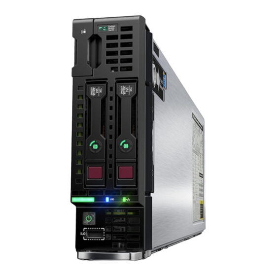
Page 6: Component Identification
Component identification Front panel components Item Description Serial label pull tab HPE c-Class Blade SUV connector (behind the serial label pull tab) Drive bay 2 Drive bay 1 iLO Service port Server blade release lever Server blade release latch The SUV connector and the c-Class Blade SUV Cable are used for some server blade configuration and diagnostic procedures. -
Page 7: Front Panel Leds And Buttons
Front panel LEDs and buttons Item Description Status NIC status LED Solid green = Link to network Flashing green (1 flash per second) = Network active Off = No network activity UID LED Solid blue = Activated Flashing blue: • 1 flash per second = Remote management or firmware upgrade in progress •... -
Page 8: Front Panel Led Power Fault Codes
Memory 3 flashes Mezzanine slots 4 flashes FlexibleLOM 5 flashes Removable HPE Flexible Smart Array controller/ 6 flashes NVMe Pass-Through Power backplane or storage backplane 8 flashes Serial label pull tab information The serial label pull tab is on the front panel of the server blade. To locate the serial label pull tab, see Front panel components on page 6. -
Page 9: Drive Numbering
Drive numbering Depending on the configuration, this server blade can support hard drives, SSDs, NVMe SSDs, and uFF drives (supported in a SFF Flash Adapter) in the drive bays. Depending on the device installed, the bay number might be different. Item Hard drive/SSD bay uFF drive bay NVMe drive bay numbering... -
Page 10: Nvme Ssd Components
Item LED Status Definition The drive is doing one of the following: Flashing green • Rebuilding • Performing a RAID migration • Performing a strip size migration • Performing a capacity expansion • Performing a logical drive extension • Erasing •... -
Page 11: Sff Flash Adapter Components And Led Definitions
Item Component Status Definition Drive removed from the PCIe bus and can be ejected. Power LED Solid green Drive is powered on and configured in system. Do not remove the drive. Flashing green Ejection request pending. Do not remove the drive. Drive removed from the PCIe bus and can be ejected. -
Page 12: Suv Cable Connectors
Item Component Description Locate • Off—Normal • Solid blue—The drive is being identified by a host application. • Flashing blue—The drive firmware is being updated or requires an update. uFF drive ejection latch Removes the uFF drive when released. Do not remove LED •... -
Page 13: System Board Components
Item Connector Description Serial For trained personnel to connect a null modem serial cable and perform advanced diagnostic procedures For connecting up to two USB 2.0 devices Video For connecting a video monitor The USB connectors on the SUV cable do not support devices that require greater than a 500mA power source. System board components Item Description... -
Page 14: System Maintenance Switch
Item Description Storage controller or NVMe pass-through board connector Mezzanine connector 1 (Type A mezzanine only) Mezzanine connector 2 (Type A or Type B mezzanine) Enclosure connector FlexibleLOM connectors (2) SAS/SATA or NVMe backplane Internal USB 3.0 connector Energy pack connector Direct-connect SATA connector System maintenance switch microSD card slot... -
Page 15: Dimm Slot Locations
Ch 5 Ch 6 For specific DIMM population information, see the DIMM population guidelines on the Hewlett Packard Enterprise website (http://www.hpe.com/docs/memory-population-rules). DIMM label identification To determine DIMM characteristics, see the label attached to the DIMM. The information in this section helps you to use the label to locate specific information about the DIMM. - Page 16 Item Description Example Capacity 8 GB 16 GB 32 GB 64 GB 128 GB Rank 1R = Single rank 2R = Dual rank 4R = Quad rank 8R = Octal rank Data width on DRAM x4 = 4-bit x8 = 8-bit x16 = 16-bit Memory generation PC4 = DDR4...
-
Page 17: Nvdimm Identification
For more information about product features, specifications, options, configurations, and compatibility, see the HPE DDR4 SmartMemory QuickSpecs on the Hewlett Packard Enterprise website (http:// www.hpe.com/support/DDR4SmartMemoryQS). NVDIMM identification NVDIMM boards are blue instead of green. This change to the color makes it easier to distinguish NVDIMMs from DIMMs. -
Page 18: Nvdimm Led Identification
• (P) is the module part number. • (L) is the technical details shown on the label. • (S) is the module serial number. Example: (P)HMN82GR7AFR4N-VK (L)16GB 1Rx4 NN4-2666V-RZZZ-10(S)80AD-01-1742-11AED5C2 NVDIMM LED identification Item LED description LED color Power LED Green Function LED Blue NVDIMM-N LED combinations... -
Page 19: Mezzanine Connector Definitions
State Definition NVDIMM-N Function LED The restore operation is in progress. Flashing The restore operation is successful. Solid or On Erase is in progress. Flashing The erase operation is successful. Solid or On The NVDIMM-N is armed, and the NVDIMM-N is in Solid or On normal operation. - Page 20 Item Description 1 and 3 Mezzanine connector 2 2 and 4 Mezzanine connector 1 Component identification...
-
Page 21: Operations
Operations Power up the server blade The OA initiates an automatic power-up sequence when the server blade is installed. If the default setting is changed, use one of the following methods to power up the server blade: • Use a virtual power button selection through iLO. •... -
Page 22: Remove The Server Blade
◦ For a controlled shutdown, select Momentary Press. ◦ For an emergency shutdown, select Press and Hold. Before proceeding, verify that the server blade is in standby mode by observing that the system power LED is amber. Remove the server blade Procedure 1. -
Page 23: Install The Access Panel
4. Press the access panel release button. 5. Slide the access panel towards the rear of the server blade, and then lift to remove the panel. Install the access panel Procedure 1. Align the access panel with the guides on the server blade in all six places and place the access panel on top of the server blade. - Page 24 IMPORTANT: When removing a DIMM baffle, do not remove the following options when installed on the DIMM baffle: • M.2 enablement option (left DIMM baffle) • HPE Smart Storage Battery (right DIMM baffle) • DIMM baffle (right side) • DIMM baffle (left side)
-
Page 25: Install The Dimm Baffles
Install the DIMM baffles The server has two DIMM baffles. Procedure 1. Align and install the DIMM baffle: IMPORTANT: When installing each DIMM baffle, be sure that the alignment tabs engage with the side of the server blade. • DIMM baffle (right side) •... -
Page 26: Remove An M.2 Ssd From The M.2 Riser Board
2. If removed, install the internal USB drive. To locate the internal USB connector, see System board components on page 13. 3. If removed, install the direct connect SATA cable (Install the direct connect SATA cable on page 4. Install the access panel on page 23. 5. -
Page 27: Remove The M.2 Interposer Board And The M.2 Riser Board
7. If necessary, repeat the M.2 SSD removal procedure for a second drive. Remove the M.2 interposer board and the M.2 riser board Procedure 1. Power down the server blade on page 21. 2. Remove the server blade on page 22. 3. -
Page 28: Relocate The Pem Nut And Rubber Stopper
Relocate the PEM nut and rubber stopper This procedure is required if the PEM nut and rubber stoppers must be relocated to support the length of the M.2 SSDs being installed. Prerequisites To remove the M.2 SSDs from the M.2 riser, you need a No. 1 Phillips screwdriver. Procedure Power down the server blade on page 21. - Page 29 Remove the PEM nuts from the M.2 riser. 10. Install the PEM nuts in the new location on the M.2 riser. CAUTION: Always install the PEM nut with the thicker edge on top of the M.2 riser and the thinner edge on the bottom of the M.2 riser. Failure to install the PEM nut in the proper orientation can cause damage to the components.
- Page 30 11. Install the rubber stoppers in the new locations to secure the PEM nuts in the M.2 riser. 12. Install the M.2 SSDs on the M.2 riser board (Installing the M.2 SSDs on page 59). 13. Install the M.2 riser board and the M.2 interposer board on the left DIMM baffle (Installing the M.2 riser board and M.2 interposer board on page 57).
-
Page 31: Remove The Direct Connect Sata Cable
Remove the direct connect SATA cable Prerequisites To remove the direct connect SATA cable, you need a T-15 Torx screwdriver. Procedure 1. Power down the server blade on page 21. 2. Remove the server blade on page 22. 3. Place the server blade on a flat, level work surface. 4. -
Page 32: Remove The Mezzanine Assembly
Remove the mezzanine assembly Procedure 1. Power down the server blade on page 21. 2. Remove the server blade on page 22. 3. Place the server blade on a flat, level work surface. 4. Remove the access panel on page 22. 5. -
Page 33: Install The Mezzanine Assembly
Install the mezzanine assembly Procedure 1. Install the mezzanine assembly 2. Install the access panel on page 23. 3. Install the server blade on page 42. 4. Power up the server blade on page 21. Remove the FlexibleLOM Procedure 1. Power down the server blade on page 21. 2. -
Page 34: Remove The Storage Controller Or Nvme Pass-Through Board
Remove the storage controller or NVMe pass-through board 1. Back up all server blade data. 2. Power down the server blade on page 21. 3. Remove the server blade on page 22. 4. Place the server blade on a flat, level work surface. 5. -
Page 35: Remove An Nvme Ssd
Remove an NVMe SSD Procedure 1. Observe the LED status of the drive and determine if it can be removed. 2. Remove the drive: a. Press the power button. The Do Not Remove button illuminates and flashes. Wait until the flashing stops and the Do Not Remove button is no longer illuminated. -
Page 36: Remove The Front Panel/Drive Cage Assembly
• M.2 enablement option (left DIMM baffle) • HPE Smart Storage Battery (right DIMM baffle) 8. Remove the front panel/drive cage assembly: a. Extend the serial label pull tab from the front of the server blade. b. Remove the two T-15 screws from the front panel/drive cage assembly. -
Page 37: Install The Front Panel/Drive Cage Assembly
Install the front panel/drive cage assembly Prerequisites To install the front panel/drive cage assembly, you need a T-15 Torx screwdriver. Procedure 1. Install the front panel/drive cage assembly: a. Extend the serial label pull tab from the front of the server blade. b. - Page 38 2. Install the DIMM baffles on page 25. 3. Do one of the following: • Install the storage controller (HPE Smart Array P204i SR Gen10 Controller option on page 48) or the NVMe pass-through board. • Install the direct connect SATA cable on page 31.
-
Page 39: Setup
After power is disconnected, battery voltage might still be present for 1s to 160s. Installing an HPE BladeSystem c-Class enclosure Before performing any server blade-specific procedures, install an HPE BladeSystem c-Class enclosure. The most current documentation for the server blade and other BladeSystem components is available on the Hewlett Packard Enterprise website. -
Page 40: Preparing The Enclosure
Preparing the enclosure Each HPE BladeSystem enclosure ships with device bay dividers to support half-height devices. If the dividers have been removed, always reinstall the dividers before installing half-height devices and device bay blanks. For more information on installing the device bay dividers, see the enclosure setup and installation guide. - Page 41 Mezzanine 2 5 and 6 Mezzanine 2 7 and 8 For detailed port mapping information, see the BladeSystem enclosure installation poster or the BladeSystem enclosure setup and installation guide on the Hewlett Packard Enterprise website. • HPE BladeSystem c3000 Enclosure Setup...
-
Page 42: Connecting To The Network
Server blade Interconnect bay Interconnect bay Notes signal number label FlexibleLOM — Mezzanine 1 Four-port cards connect to bay 2. Mezzanine 2 3 and 4 ◦ Four-port cards ◦ Ports 1 and 3 connect to bay 3. ◦ Ports 2 and 4 connect to bay 4. Connecting to the network To connect the BladeSystem to a network, each enclosure must be configured with network interconnect devices to manage signals between the server blades and the external network. - Page 43 For the best possible BladeSystem and Virtual Connect experience, and to prevent a future reboot, Hewlett Packard Enterprise requires updating the Onboard Administrator and Virtual Connect to the correct version before installing an HPE ProLiant Gen10 server blade. The version information is on the tag on the front of the server blade.
-
Page 44: Completing The Configuration
Completing the configuration To complete the server blade and BladeSystem configuration, see the overview card that ships with the enclosure. Setup... -
Page 45: Hardware Options Installation
To support SAS and SATA hard drives or SSDs, install the SAS/SATA HDD backplane with one of the following: • Direct connect SATA cable (supports SATA drives only) • HPE Smart Array P204i SR Gen10 Controller (supports both SAS and SATA drives) Procedure 1. Remove the drive blank. Hardware options installation... -
Page 46: Installing The Nvme Ssd Options
2. Prepare the drive. 3. Install the drive. 4. Determine the status of the drive from the drive LED definitions. For more information, see Hot-plug drive LED definitions on page 9. Installing the NVMe SSD options The server blade supports hot-plug NVMe SSDs when configured for NVMe drive support. Prerequisites Before installing an NVMe SSD into a server blade, the server blade must be configured with the following components:... -
Page 47: Installing The Sff Flash Adapter Option
To support uFF drives and the SFF Flash Adapter option, install the SAS/SATA HDD backplane with one of the following: • Direct connect SATA cable • HPE Smart Array P204i SR Gen10 Controller Procedure 1. Remove the drive blank. Hardware options installation... -
Page 48: Hpe Smart Array P204I Sr Gen10 Controller Option
3. Install the SFF Flash Adapter by pushing firmly near the left-side adapter ejection handle until the latching spring engages in the drive bay. HPE Smart Array P204i SR Gen10 Controller option When the HPE Smart Array P204i SR Gen10 Controller is installed, this server blade supports the following options: •... - Page 49 Prerequisites To support this storage controller, the SAS/SATA backplane is installed on the server blade. For server blades that support NVMe drives, an NVMe backplane is installed and an NVMe passthrough board will be installed in this location. Procedure Back up all server blade data. Power down the server blade on page 21.
-
Page 50: Hpe Smart Storage Battery
11. Install the server blade on page 42. 12. Power up the server blade on page 21. HPE Smart Storage Battery The HPE Smart Storage Battery supports the following devices: HPE Smart Array SR controllers A single 96W battery can support up to 24 devices. -
Page 51: Installing The Hpe Smart Storage Battery
A danger of explosion exists if the battery is installed incorrectly. System ROM and firmware messages may display "energy pack" in place of "Smart Storage Battery." Energy pack refers to both HPE Smart Storage Batteries and HPE Smart Storage Hybrid Capacitors. Procedure Power down the server blade on page 21. - Page 52 IMPORTANT: When installing each DIMM baffle, be sure that the alignment tabs engage with the side of the server blade. 10. Align and install the DIMM baffle. Press down on the cable connector to fully seat the HPE Smart Storage Battery cable connector to the system board. Hardware options installation...
-
Page 53: Mezzanine Card Option
11. If removed, install the direct connect SATA cable (Install the direct connect SATA cable on page 31). 12. If removed, install the internal USB drive. To locate the internal USB connector, see System board components on page 13. 13. Install the access panel on page 23. 14. - Page 54 Procedure Power down the server blade on page 21. Remove the server blade on page 22. Place the server blade on a flat, level work surface. Remove the access panel on page 22. Remove the mezzanine assembly on page 32. Align the mezzanine card using the appropriate guide pins on the mezzanine assembly.
-
Page 55: Flexiblelom Option
Install the access panel on page 23. 10. Install the server blade on page 42. 11. Power up the server blade on page 21. FlexibleLOM option Installing the FlexibleLOM Procedure Power down the server blade on page 21. Remove the server blade on page 22. Place the server blade on a flat, level work surface. -
Page 56: M.2 Enablement Option
Install the mezzanine assembly on page 33. Install the access panel on page 23. Install the server blade on page 42. 10. Power up the server blade on page 21. M.2 enablement option The M.2 enablement option consists of an M.2 riser and an M.2 interposer board that installs on the left DIMM baffle. -
Page 57: Installing The M.2 Riser Board And M.2 Interposer Board
1. Supports M.2 2280 SSD installation 2. Supports M.2 22110 SSD installation Installing the M.2 riser board and M.2 interposer board The M.2 riser board supports two M.2 SSDs. This server blade does not support mixing M.2 SSD sizes or bus protocols. - Page 58 Install the M.2 interposer board on the left DIMM baffle. IMPORTANT: MLB is printed on the M.2 interposer board to indicate edge of the board that connects to the system board. When the M.2 interposer board is installed, MLB must face out towards the edge of the server blade.
-
Page 59: Installing The M.2 Ssds
11. Install the access panel on page 23. 12. Install the server blade on page 42. 13. Power up the server blade on page 21. Installing the M.2 SSDs Prerequisites A No. 1 Phillips screwdriver is required to perform this procedure. Procedure Power down the server blade on page 21. -
Page 60: Memory Options
DIMM and NVDIMM population information For specific DIMM and NVDIMM population information, see the DIMM population guidelines on the Hewlett Packard Enterprise website (http://www.hpe.com/docs/memory-population-rules). DIMM-processor compatibility The installed processor determines the type of DIMM that is supported in the server blade: •... - Page 61 DIMM baffle: • M.2 enablement option (left DIMM baffle) • HPE Smart Storage Battery (right DIMM baffle) Remove the DIMM baffles on page 23. Open the appropriate DIMM slot latches. Install the DIMM. Install the DIMM baffles on page 25.
-
Page 62: Hpe 16Gb Nvdimm Option
Xeon Scalable processors. The server blade can support up to 12 NVDIMMs in 2 socket servers (up to 192GB) and up to 24 NVDIMMs in 4 socket servers (up to 384GB). The HPE Smart Storage Battery provides backup power to the memory slots allowing data to be moved from the DRAM portion of the NVDIMM to the Flash portion for persistence during a power down event. - Page 63 Locate any NVDIMMs already installed in the server blade. Verify that all LEDs on any installed NVDIMMs are off. Install the NVDIMM. Install and connect the HPE Smart Storage Battery, if it is not already installed (HPE Smart Storage Battery option). Hardware options installation...
- Page 64 10. Install any components removed to access the DIMM slots and the HPE Smart Storage Battery. 11. Install the access panel on page 23. 12. Install the server blade on page 42. 13. Power up the server blade on page 21.
- Page 65 (such as disintegrate, pulverize, melt, incinerate, or shred) The NVDIMM-N Sanitize options are intended to meet the Purge level. For more information on sanitization for NVDIMMs, see the following sections in the HPE 16GB NVDIMM User Guide on the Hewlett Packard Enterprise website (http://www.hpe.com/info/nvdimm-docs): •...
-
Page 66: Installing The Processor-Heatsink Assembly
Intelligent System Tuning supports specific processors and configurations. For more information, see the product QuickSpecs on the Hewlett Packard Enterprise website (http://www.hpe.com/info/qs). IMPORTANT: Existing HPE ProLiant and HPE Synergy Gen10 server products containing first- generation Intel Xeon Scalable processors may not be upgraded to second-generation Intel Xeon Scalable processors at this time. - Page 67 Power down the server blade on page 21. Remove the server blade on page 22. Remove the access panel on page 22. Remove the DIMM baffles on page 23. Remove the heatsink blank. Retain the heatsink blank for future use. Install the processor-heatsink assembly: a.
-
Page 68: Hpe Trusted Platform Module 2.0 Gen10 Option
HPE Trusted Platform Module 2.0 Gen10 option Overview Use these instructions to install and enable an HPE TPM 2.0 Gen10 Kit in a supported server blade. This option is not supported on Gen9 and earlier server blades. This procedure includes three sections: 1. -
Page 69: Tpm 2.0 Location
IMPORTANT: In UEFI Boot Mode, the HPE TPM 2.0 Gen10 Kit can be configured to operate as TPM 2.0 (default) or TPM 1.2 on a supported server blade. In Legacy Boot Mode, the configuration can be changed between TPM 1.2 and TPM 2.0, but only TPM 1.2 operation is supported. -
Page 70: Installing And Enabling The Hpe Tpm 2.0 Gen10 Kit
Hewlett Packard Enterprise is not liable for blocked data access caused by improper TPM use. For operating instructions, see the TPM documentation or the encryption technology feature documentation provided by the operating system. Installing and enabling the HPE TPM 2.0 Gen10 Kit Installing the Trusted Platform Module board Preparing the server blade for installation Procedure 1. - Page 71 Installing the TPM board and cover Procedure 1. Observe the following alerts: CAUTION: If the TPM is removed from the original server blade and powered up on a different server blade, data stored in the TPM including keys will be erased. CAUTION: The TPM is keyed to install only in the orientation shown.
-
Page 72: Enabling The Trusted Platform Module
4. Proceed to Preparing the server blade for operation on page 72. Preparing the server blade for operation Procedure 1. Install any options or cables previously removed to access the TPM connector. 2. Install the access panel on page 23. 3. - Page 73 • "Current TPM Type" is set to TPM 2.0. • "Current TPM State" is set to Present and Enabled. • "TPM Visibility" is set to Visible. 4. If changes were made in the previous step, press the F10 key to save your selection. 5.
- Page 74 For more information, see the Microsoft website. Retaining the recovery key/password The recovery key/password is generated during BitLocker setup, and can be saved and printed after BitLocker is enabled. When using BitLocker, always retain the recovery key/password. The recovery key/ password is required to enter Recovery Mode after BitLocker detects a possible compromise of system integrity.
-
Page 75: Cabling
Cabling configurations and requirements vary depending on the product and installed options. For more information about product features, specifications, options, configurations, and compatibility, see the product QuickSpecs on the Hewlett Packard Enterprise website (http://www.hpe.com/info/qs). HPE Smart Storage Battery cabling Direct connect SATA cabling... -
Page 76: Using The Hpe C-Class Blade Suv Cable
Using the HPE c-Class Blade SUV Cable The c-Class Blade SUV Cable enables the user to perform server blade administration, configuration, and diagnostic procedures by connecting video and USB devices directly to the server blade. For SUV cable connectors, see "SUV cable connectors."... -
Page 77: Accessing A Server Blade With Local Kvm
Numerous configurations are possible. This section offers two possible configurations. For more information, see USB support on page 89. Accessing a server blade with local KVM Prerequisites For this configuration, a USB hub is not necessary. To connect additional devices, use a USB hub. CAUTION: Before disconnecting the SUV cable from the connector, always squeeze the release buttons on the sides of the connector. - Page 78 provides additional connections and the power required to support USB keys or external drives that require more than 500mA at 5V. Procedure 1. Open the serial label pull tab and connect the c-Class Blade SUV cable to the server blade. 2.
-
Page 79: Troubleshooting
• Error Message Guide for HPE ProLiant Gen10 servers and HPE Synergy provides a list of error messages and information to assist with interpreting and resolving error messages. •... -
Page 80: Software And Configuration Utilities
Product QuickSpecs For more information about product features, specifications, options, configurations, and compatibility, see the product QuickSpecs on the Hewlett Packard Enterprise website (http://www.hpe.com/info/qs). Active Health System Viewer Active Health System Viewer (AHSV) is an online tool used to read, diagnose, and resolve server issues quickly using AHS uploaded data. -
Page 81: Active Health System
Health System Viewer documentation at the following website: http://www.hpe.com/support/ahsv-docs. HPE iLO 5 iLO 5 is a remote server management processor embedded on the system boards of HPE ProLiant servers and Synergy compute modules. iLO enables the monitoring and controlling of servers from remote locations. -
Page 82: Ilo Federation
Features that enhance server administrator productivity and additional new security features are licensed. For more information, see the iLO licensing guide at the following website: http://www.hpe.com/support/ ilo-docs. For more information about iLO, see the iLO user guide at the following website: http://www.hpe.com/ support/ilo-docs. iLO Federation iLO Federation enables you to manage multiple servers from one system using the iLO web interface. -
Page 83: Ilo Restful Api
For more information, watch the Redfish & How it works with HPE Server Management video. RESTful Interface Tool The RESTful Interface Tool (iLOREST) is a scripting tool that allows you to automate HPE server management tasks. It provides a set of simplified commands that take advantage of the iLO RESTful API. -
Page 84: Intelligent Provisioning
Intelligent Provisioning 3.30 and later includes HPE SMB Setup. When you launch F10 mode from the POST screen, you are prompted to select whether you want to enter the Intelligent Provisioning or HPE SMB Setup mode. -
Page 85: Management Security
Management Security HPE ProLiant Gen10 servers are built with some of the industry's most advanced security capabilities, out of the box, with a foundation of secure embedded management applications and firmware. The management security provided by HPE embedded management products enables secure support of modern workloads, protecting your components from unauthorized access and unapproved use. -
Page 86: Uefi System Utilities
Selecting the primary boot controller or partition. • Configuring memory options. • Launching other preboot environments. HPE servers with UEFI can provide: • Support for boot partitions larger than 2.2 TB. Such configurations could previously only be used for boot drives when using RAID solutions. •... -
Page 87: Secure Boot
Using the System Utilities options described in the following sections. • Using the iLO RESTful API to clear and restore certificates. For more information, see the Hewlett Packard Enterprise website (http://www.hpe.com/info/redfish). • Using the secboot command in the Embedded UEFI Shell to display Secure Boot databases, keys, and security reports. -
Page 88: Hpe Smart Storage Administrator
HPE Smart Storage Administrator HPE SSA is the main tool for configuring arrays on HPE Smart Array SR controllers. It exists in three interface formats: the HPE SSA GUI, the HPE SSA CLI, and HPE SSA Scripting. All formats provide support for configuration tasks. -
Page 89: Usb Support
Provides automatic collection and analysis of the sensor and telemetry data from AHS to derive insights from the behaviors of the install base to provide recommendations to resolve problems and improve performance For more information on getting started and using HPE InfoSight for servers, go to: http://www.hpe.com/ info/infosight-servers-docs. USB support Hewlett Packard Enterprise Gen10 server blades support all USB operating speeds depending on the device that is connected to the server blade. - Page 90 NOTE: SUM does not support third-party controllers, including flashing hard drives behind the controllers. Smart Update Tools Smart Update Tools is a software utility used with iLO 4, HPE OneView, Service Pack for ProLiant (SPP), and Smart Update Manager (SUM) to stage, install, and activate firmware and driver updates.
- Page 91 • Smart Update Tools: Polls iLO to check for requests from HPE OneView for updates through the management network and orchestrates staging, deploying, and activating updates. You can adjust the polling interval by issuing the appropriate command-line option provided by iSUT. Performs inventory on target servers, stages deployment, deploys updates, and then reboots the servers.
-
Page 92: Drivers
• Download individual drivers, firmware, or other system software components from the server blade product page in the Hewlett Packard Enterprise Support Center website (http://www.hpe.com/ support/hpesc). Operating system version support For information about specific versions of a supported operating system, refer to the operating system support matrix. -
Page 93: Hpe Pointnext Portfolio
HPE Pointnext Portfolio HPE Pointnext delivers confidence, reduces risk, and helps customers realize agility and stability. Hewlett Packard Enterprise helps customers succeed through Hybrid IT by simplifying and enriching the on- premise experience, informed by public cloud qualities and attributes. -
Page 94: Removing And Replacing The System Battery
Removing and replacing the system battery If the server blade no longer automatically displays the correct date and time, then replace the battery that provides power to the real-time clock. Under normal use, battery life is 5 to 10 years. WARNING: The computer contains an internal lithium manganese dioxide, a vanadium pentoxide, or an alkaline battery pack. - Page 95 To replace the component, reverse the removal procedure. For more information about battery replacement or proper disposal, contact an authorized reseller or an authorized service provider. Removing and replacing the system battery...
-
Page 96: Electrostatic Discharge
Electrostatic discharge Preventing electrostatic discharge To prevent damaging the system, be aware of the precautions you must follow when setting up the system or handling parts. A discharge of static electricity from a finger or other conductor may damage system boards or other static-sensitive devices. This type of damage may reduce the life expectancy of the device. -
Page 97: Specifications
Specifications Environmental specifications Specification Value Temperature range — Operating 10°C to 35°C (50°F to 95°F) Nonoperating -30°C to 60°C (-22°F to 140°F) Relative humidity (noncondensing) — Operating 10% to 90% @ 28°C (82.4°F) Nonoperating 5% to 95% @ 38.7°C (101.7°F) Altitude —... -
Page 98: Websites
Websites General websites Hewlett Packard Enterprise Information Library www.hpe.com/info/EIL Single Point of Connectivity Knowledge (SPOCK) Storage compatibility matrix www.hpe.com/storage/spock Storage white papers and analyst reports www.hpe.com/storage/whitepapers For additional websites, see Support and other resources. Websites... -
Page 99: Support And Other Resources
Support and other resources Accessing Hewlett Packard Enterprise Support • For live assistance, go to the Contact Hewlett Packard Enterprise Worldwide website: http://www.hpe.com/info/assistance • To access documentation and support services, go to the Hewlett Packard Enterprise Support Center website: http://www.hpe.com/support/hpesc Information to collect •... -
Page 100: Customer Self Repair
IMPORTANT: Access to some updates might require product entitlement when accessed through the Hewlett Packard Enterprise Support Center. You must have an HPE Passport set up with relevant entitlements. Customer self repair Hewlett Packard Enterprise customer self repair (CSR) programs allow you to repair your product. If a CSR part needs to be replaced, it will be shipped directly to you so that you can install it at your convenience. -
Page 101: Regulatory Information
Documentation Feedback (docsfeedback@hpe.com). When submitting your feedback, include the document title, part number, edition, and publication date located on the front cover of the document. For online help content, include the product name, product version, help edition, and publication date located on the legal notices page.
Need help?
Do you have a question about the ProLiant BL460c Gen10 and is the answer not in the manual?
Questions and answers