Table of Contents
Advertisement
Quick Links
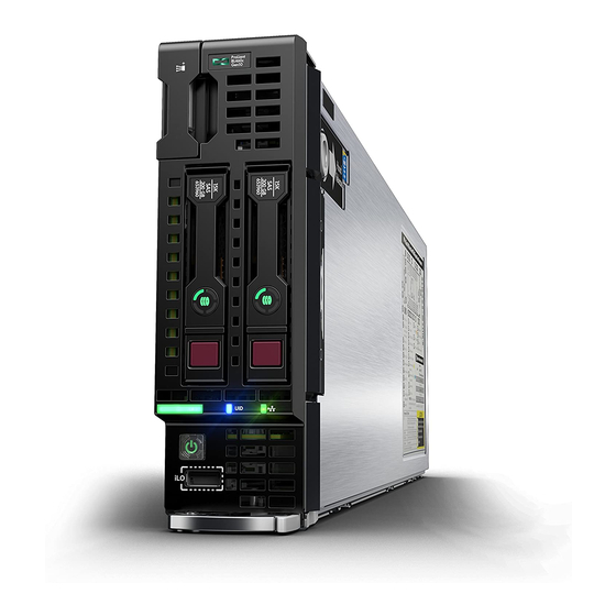
HPE ProLiant BL460c Gen10 Server Blade Maintenance
and Service Guide
Abstract
This guide describes identification and maintenance procedures, diagnostic tools, specifications and requirements for
hardware components and software. This guide is for an experienced service technician. Hewlett Packard Enterprise
assumes you are qualified in the servicing of computer equipment, trained in recognizing hazards in products, and are
familiar with weight and stability precautions.
Part Number: 876834-009
Published: April 2020
Edition: 9
Advertisement
Table of Contents

Related Manuals for HPE ProLiant BL460c Gen10


Summary of Contents for HPE ProLiant BL460c Gen10
- Page 1 HPE ProLiant BL460c Gen10 Server Blade Maintenance and Service Guide Abstract This guide describes identification and maintenance procedures, diagnostic tools, specifications and requirements for hardware components and software. This guide is for an experienced service technician. Hewlett Packard Enterprise assumes you are qualified in the servicing of computer equipment, trained in recognizing hazards in products, and are familiar with weight and stability precautions.
- Page 2 © Copyright 2017-2020 Hewlett Packard Enterprise Development LP Notices The information contained herein is subject to change without notice. The only warranties for Hewlett Packard Enterprise products and services are set forth in the express warranty statements accompanying such products and services. Nothing herein should be construed as constituting an additional warranty.
-
Page 3: Table Of Contents
Optional server components....................................14 Drive spare parts......................................15 Drive backplane spare parts................................. 19 HPE SFF Flash Adapter with dual micro form factor (uFF) SSDs spare parts............19 M.2 enablement kit spare parts................................19 M.2 SSD spare parts....................................19 Mezzanine card option spare parts..............................20 HPE Smart Storage Battery spare parts............................20... - Page 4 Removing and replacing a storage controller or NVMe pass-through board................63 Removing a storage controller or NVMe pass-through board..................63 Replacing a storage controller or NVMe pass-through board..................64 Removing and replacing the HPE Smart Storage Battery........................66 Removing the HPE Smart Storage Battery..........................67 Replacing the HPE Smart Storage Battery..........................68 Removing and replacing the front panel/drive cage assembly......................
- Page 5 Cabling resources........................................104 HPE Smart Storage Battery cabling................................104 Direct connect SATA cabling....................................104 Using the HPE c-Class Blade SUV Cable..............................105 Disconnecting and replacing the SUV cable..............................105 Connecting locally to a server blade with video and USB devices....................105 Accessing a server blade with local KVM...........................106 Accessing local media devices................................106...
- Page 6 Support and other resources..................109 Accessing Hewlett Packard Enterprise Support............................. 109 Accessing updates........................................109 Customer self repair.........................................110 Remote support..........................................110 Warranty information......................................110 Regulatory information......................................111 Documentation feedback......................................111...
-
Page 7: Illustrated Parts Catalog
Illustrated parts catalog Mechanical components Hewlett Packard Enterprise continually improves and changes product parts. For complete and current supported parts information, see the Hewlett Packard Enterprise PartSurfer website (http://www.hpe.com/info/partssurfer). Item Description Access panel spare parts DIMM baffle spare parts Heatsink blank spare parts... -
Page 8: Heatsink Blank Spare Parts
Customer self repair: mandatory Description Spare part number Drive blank 670033-001 System components Hewlett Packard Enterprise continually improves and changes product parts. For complete and current supported parts information, see the Hewlett Packard Enterprise PartSurfer website (http://www.hpe.com/info/partssurfer). Illustrated parts catalog... -
Page 9: Front Panel/Drive Cage Assembly Spare Parts
Front panel/drive cage assembly spare parts System board with base pan spare parts Storage controller/NVMe pass-through board spare parts System battery spare part DIMM spare parts HPE 16GB NVDIMM spare part — Heatsink spare parts First-generation Intel Xeon Scalable Processor spare parts •... -
Page 10: Storage Controller/Nvme Pass-Through Board Spare Parts
P11566-001 Second Generation Intel Xeon Scalable Processors) Storage controller/NVMe pass-through board spare parts Customer self repair: optional Description Spare part number HPE Smart Array P204i-b SR Controller 836263-001 HPE Smart Array P408e-m SR Controller 836264-001 NVMe pass-through board 877975-001 System battery spare part... -
Page 11: Hpe 16Gb Nvdimm Spare Part
P06190-001 64-GB, 2Rx4 PC4-2933Y-R P06192-001 64-GB, 2Rx4 PC4-2933Y-R SAM P12418-001 128-GB, 8Rx4 PC4-2933Y-L 3DS P06191-001 HPE 16GB NVDIMM spare part Customer self repair: mandatory Description Spare part number NVDIMM 16GB 1Rx4 NN4-2666V-R 874540-001 Heatsink spare parts Customer self repair: no... -
Page 12: Second-Generation Intel Xeon Scalable Processor Spare Parts
Table 5: 51XX processors Description Spare part number Xeon-G 5115 10c 2.4-GHz 85W 878082-001 Xeon-G 5118 12c 2.3-GHz 105W 875717-001 Xeon-G 5120 14c 2.2-GHz 105W 875718-001 Xeon-G 5122 4c 3.6-GHz 105W 875719-001 Table 6: 61XX processors Description Spare part number Xeon-G 6126 12c 2.6-GHz 125W 875720-001 Xeon-G 6128 6c 3.4-GHz 115W... - Page 13 Table 9: 42XX processors Description Spare part number Xeon-S 4208 8c 2.1GHz 85W P11605-001 Xeon-S 4210 10c 2.2GHz 85W P11606-001 Xeon-S 4214 12c 2.2GHz 85W P11607-001 Xeon-S 4214Y 12/10/8c 2.2/2.3/2.4GHz 105W P11636-001 Xeon-S 4215 8c 2.5GHz 85W P11608-001 Xeon-S 4216 16c 2.2GHz 85W P11609-001 Table 10: 52XX processors Description...
-
Page 14: Flexiblelom Adapter Spare Parts
Customer self repair: mandatory Description Spare part number Direct connect SATA cable 877979-001 Optional server components Hewlett Packard Enterprise continually improves and changes product parts. For complete and current supported parts information, see the Hewlett Packard Enterprise PartSurfer website (http://www.hpe.com/info/partssurfer). Illustrated parts catalog... -
Page 15: Drive Spare Parts
Item Description Drive spare parts Drive backplane spare parts HPE SFF Flash Adapter with dual micro form factor (uFF) SSDs spare parts M.2 enablement kit spare parts M.2 SSD spare parts Mezzanine card option spare parts HPE Smart Storage Battery spare parts Trusted Platform Module spare parts For more information, see Removal and replacement procedures. - Page 16 Description Spare part number 600 GB, HDD, SAS, 12G, 10K, SC, DS 872736-001 600 GB, HDD, SAS, 12G, 15K, SC, DS, ENT 870794-001 900 GB, HDD, SAS, 12G, 15K, SC, DS, ENT 870795-001 1 TB, HDD, SATA, 6G, 7.2K, MDL, SC 656108-001 1 TB, HDD, SAS, 12G, 7.5K, MDL, SC 832984-001...
- Page 17 Description Spare part number 480 GB, SSD, SATA, RI, SC, DS P05320-001 480 GB, SSD, SATA, RI, SC, DS P05312-001 800 GB, SSD, SAS, MU, SC, DS P09923-001 800 GB, SSD, SAS, MU, SD, DS P06577-001 800 GB, SSD, SAS, WI, SC, DS P09948-001 800 GB, SSD, SAS, WI, SC, DS P06602-001...
- Page 18 Description Spare part number 3.2 TB, SSD, SAS, MU, SC, DS P06582-001 3.2 TB, SSD, SAS, WI, SC, DS P06605-001 3.84 TB, SSD, SAS, MU, SC, VS, DS P10610-001 3.84 TB, SSD, SAS, RI, SC, DS P08610-001 3.84 TB, SSD, SAS, RI, SC, DS P06598-001 3.84 TB, SSD, SAS, RI, SC, VS, DS P10639-001...
-
Page 19: Drive Backplane Spare Parts
Description Spare part number SAS/SATA drive backplane 877970-001 NVMe drive backplane 877974-001 HPE SFF Flash Adapter with dual micro form factor (uFF) SSDs spare parts Customer self repair: mandatory Description Spare part number SFF Flash Adapter 830452-001 120 GB, SATA, SSD, 6G, uFF... -
Page 20: Mezzanine Card Option Spare Parts
HPE Ethernet 10Gb 2-port 560M Adapter 669282-001 HPE InfiniBand FDR/Ethernet 40Gb two-port 544+M 764735-001 Adapter HPE LPe1605 16Gb Fibre Channel HBA for BladeSystem 718577-001 c-Class HPE QMH2672 16Gb Fibre Channel Host Bus Adapter 711305-001 HPE Smart Array P408e-m Mezz SR Gen10 Controller... -
Page 21: Customer Self Repair
Customer self repair Hewlett Packard Enterprise products are designed with many Customer Self Repair (CSR) parts to minimize repair time and allow for greater flexibility in performing defective parts replacement. If during the diagnosis period Hewlett Packard Enterprise (or Hewlett Packard Enterprise service providers or service partners) identifies that the repair can be accomplished by the use of a CSR part, Hewlett Packard Enterprise will ship that part directly to you for replacement. - Page 22 REMARQUE: Certaines pièces Hewlett Packard Enterprise ne sont pas conçues pour permettre au client d'effectuer lui- même la réparation. Pour que la garantie puisse s'appliquer, Hewlett Packard Enterprise exige que le remplacement de la pièce soit effectué par un Mainteneur Agréé. Ces pièces sont identifiées par la mention "Non" dans le Catalogue illustré. Les pièces CSR sont livrées le jour ouvré...
- Page 23 Per il servizio di garanzia per i soli componenti è obbligatoria la formula CSR che prevede la riparazione da parte del cliente. Se il cliente invece richiede la sostituzione ad Hewlett Packard Enterprise dovrà sostenere le spese di spedizione e di manodopera per il servizio.
- Page 24 • Obligatorio—Componentes cuya reparación por parte del usuario es obligatoria. Si solicita a Hewlett Packard Enterprise que realice la sustitución de estos componentes, tendrá que hacerse cargo de los gastos de desplazamiento y de mano de obra de dicho servicio. Opcional—Componentes cuya reparación por parte del usuario es opcional.
- Page 25 Afhankelijk van de leverbaarheid en de locatie worden CSR-onderdelen verzonden voor levering op de eerstvolgende werkdag. Levering op dezelfde dag of binnen vier uur kan tegen meerkosten worden aangeboden, indien dit mogelijk is gezien de locatie. Indien assistentie is gewenst, belt u het Hewlett Packard Enterprise Support Center om via de telefoon ondersteuning van een technicus te ontvangen.
- Page 26 Serviço de garantia apenas para peças A garantia limitada da Hewlett Packard Enterprise pode incluir um serviço de garantia apenas para peças. Segundo os termos do serviço de garantia apenas para peças, a Hewlett Packard Enterprise fornece as peças de reposição sem cobrar nenhuma taxa.
- Page 27 Customer self repair...
- Page 28 Customer self repair...
- Page 29 Customer self repair...
-
Page 30: Removal And Replacement Procedures
Removal and replacement procedures Required tools The following tools might be required to perform some procedures: • T-15 Torx screwdriver • No. 1 Phillips screwdriver Safety considerations Before performing service procedures, review all the safety information. Preventing electrostatic discharge To prevent damaging the system, be aware of the precautions you must follow when setting up the system or handling parts. -
Page 31: Symbols On Equipment
WARNING: To reduce the risk of fire or burns after removing the energy pack: • Do not disassemble, crush, or puncture the energy pack. • Do not short external contacts. • Do not dispose of the energy pack in fire or water. After power is disconnected, battery voltage might still be present for 1s to 160s. -
Page 32: Server Blade Preparation
These symbols, on power supplies or systems, indicate that the equipment is supplied by multiple sources of power. WARNING: To reduce the risk of injury from electric shock, remove all power cords to disconnect power from the system completely. Server blade preparation To service any internal server blade component, power down the server blade and remove it from the enclosure. -
Page 33: Remove The Server Blade
1. Select the Enclosure Information tab. 2. In the Device Bays item, select the server. 3. From the Virtual Power menu, initiate a shutdown of applications and the OS: ◦ For a controlled shutdown, select Momentary Press. For an emergency shutdown, select Press and Hold. ◦... -
Page 34: Install The Server Blade
Enterprise requires updating the Onboard Administrator and Virtual Connect to the correct version before installing an HPE ProLiant Gen10 server blade. The version information is on the tag on the front of the server blade. For more information on this and other specific firmware and driver requirements, as well as the latest firmware and driver versions, download the latest SPP from the Hewlett Packard Enterprise website (http://www.hpe.com/servers/spp/... -
Page 35: Remove The Enclosure Connector Cover
3. Install the server blade. Remove the enclosure connector cover Procedure 1. Place the server blade on a flat, level work surface. 2. Remove the enclosure connector cover. Removal and replacement procedures... -
Page 36: Relocate The Pem Nut And Rubber Stopper
Relocate the PEM nut and rubber stopper This procedure is required if the PEM nut and rubber stoppers must be relocated to support the length of the M.2 SSDs being installed. Prerequisites To remove the M.2 SSDs from the M.2 riser, you need a No. 1 Phillips screwdriver. Procedure Power down the server blade. - Page 37 Remove the PEM nuts from the M.2 riser. 10. Install the PEM nuts in the new location on the M.2 riser. CAUTION: Always install the PEM nut with the thicker edge on top of the M.2 riser and the thinner edge on the bottom of the M.2 riser.
- Page 38 11. Install the rubber stoppers in the new locations to secure the PEM nuts in the M.2 riser. 12. Install the M.2 SSDs on the M.2 riser board. 13. Install the M.2 riser board and the M.2 interposer board on the left DIMM baffle (Installing the M.2 riser board and M.2 interposer board).
-
Page 39: Remove The M.2 Interposer Board And The M.2 Riser Board
Remove the M.2 interposer board and the M.2 riser board Procedure 1. Power down the server blade. 2. Remove the server blade. 3. Place the server blade on a flat, level work surface. 4. Remove the access panel (Removing the access panel). 5. -
Page 40: Installing The M.2 Riser Board And M.2 Interposer Board
Installing the M.2 riser board and M.2 interposer board The M.2 riser board supports two M.2 SSDs. This server blade does not support mixing M.2 SSD sizes or bus protocols. Prerequisites To install the M.2 SSDs on the M.2 riser board, you need a No. 1 Phillips screwdriver. Procedure Power down the server blade. - Page 41 Install the M.2 interposer board on the left DIMM baffle. IMPORTANT: MLB is printed on the M.2 interposer board to indicate edge of the board that connects to the system board. When the M.2 interposer board is installed, MLB must face out towards the edge of the server blade.
-
Page 42: Removing And Replacing The Access Panel
11. Replacing the access panel. 12. Install the server blade. 13. Power up the server blade. Removing and replacing the access panel Removing the access panel Procedure 1. Power down the server blade. 2. Remove the server blade. 3. Place the server blade on a flat, level work surface. 4. -
Page 43: Replacing The Access Panel
Replacing the access panel Procedure 1. Align the access panel with the guides on the server blade in all six locations and place the access panel on the server blade. 2. Slide the access panel forward until it clicks into place. 3. -
Page 44: Removing And Replacing An Sff Drive
CAUTION: To prevent improper cooling and thermal damage, do not operate the server blade unless all device bays are populated with either a component or a blank. To replace the blank, slide the blank into the bay until it locks into place. Removing and replacing an SFF drive Procedure 1. -
Page 45: Removing And Replacing The Sff Flash Adapter Option
To replace the NVMe SSD, press the Do Not Remove button to open the release lever. Slide the drive completely into the drive bay and close the release lever. More information NVMe SSD components Removing and replacing the SFF Flash Adapter option CAUTION: To prevent improper cooling and thermal damage, do not operate the server blade or the enclosure unless all device bays are populated with either a component or a blank. -
Page 46: Removing And Replacing Dimm Baffles
• M.2 enablement option (left DIMM baffle) • HPE Smart Storage Battery (right DIMM baffle) 6. If installed, remove the direct connect SATA cable from cable channel on the right air baffle. 7. Remove one or more DIMM baffles: Removal and replacement procedures... -
Page 47: Replacing The Dimm Baffles
• DIMM baffle (right side) — If installed, use the blue pull tab to disconnect the HPE Smart Storage Battery cable from the system board. • DIMM baffle (left side) More information Power down the server blade Remove the server blade... - Page 48 IMPORTANT: When installing each DIMM baffle, be sure that the alignment tabs engage with the side of the server blade. • DIMM baffle (right side) • DIMM baffle (left side) 2. If removed, install the internal USB drive. To locate the internal USB connector, see System board components. 3.
-
Page 49: Dimm-Processor Compatibility
M.2 enablement option (left DIMM baffle) • HPE Smart Storage Battery (right DIMM baffle) IMPORTANT: When removing the right DIMM baffle, use the blue pull tab to disconnect the HPE Smart Storage Battery cable from the system board. 6. Remove the DIMM. -
Page 50: Removing And Replacing An Nvdimm
To replace the DIMM, open the DIMM slot latches, and then install the DIMM. Be sure to then replace all other components that were removed for removing the DIMM. More information Power down the server blade Remove the server blade Removing the access panel Removing the DIMM baffles Removing and replacing an NVDIMM... -
Page 51: Nvdimm-Processor Compatibility
• HPE Smart Storage Battery (right DIMM baffle) IMPORTANT: When removing the right DIMM baffle, use the blue pull tab to disconnect the HPE Smart Storage Battery cable from the system board. 6. Remove both DIMM baffles (Removing the DIMM baffles). -
Page 52: Nvdimm Relocation Guidelines
(such as disintegrate, pulverize, melt, incinerate, or shred) The NVDIMM-N Sanitize options are intended to meet the Purge level. For more information on sanitization for NVDIMMs, see the following sections in the HPE 16GB NVDIMM User Guide on the Hewlett Packard Enterprise website (http://www.hpe.com/info/nvdimm-docs): •... -
Page 53: Recovering Restored Data From An Nvdimm-N Dram
Extend or remove the server blade. Remove the access panel. Remove all components necessary to access the server blade DIMM slots and the HPE Smart Storage Battery. For more information, see the server blade maintenance and service guide on the Hewlett Packard Enterprise website (http://www.hpe.com/info/enterprise-docs). -
Page 54: Configuring The Server Blade For Nvdimms
F9 key during POST. For more information about UEFI System Utilities, see the Hewlett Packard Enterprise website (http://www.hpe.com/info/uefi/docs). • iLO RESTful API for HPE iLO 5—For more information about configuring the system for NVDIMMs, see https:// hewlettpackard.github.io/ilo-rest-api-docs/ilo5/. Removing and replacing the M.2 enablement option Removing the M.2 enablement option... -
Page 55: Replacing The M.2 Enablement Option
More information Power down the server blade Remove the server blade Removing the access panel Removing the DIMM baffles Replacing the M.2 enablement option Procedure 1. Verify that the PEM nuts and rubber stoppers are in the correct location to support the length of the M.2 SSDs being installed. - Page 56 4. Install the M.2 interposer board on the left DIMM baffle until it clicks into place. 5. Install the left DIMM baffle. 6. Install the access panel. 7. Install the server blade. 8. Power up the server blade. More information Power up the server blade Removing and replacing an M.2 SSD Replacing the DIMM baffles...
-
Page 57: Removing And Replacing An M.2 Ssd
Removing and replacing an M.2 SSD Prerequisites A No. 1 Phillips screwdriver is required to perform this procedure. Procedure 1. Power down the server blade. 2. Remove the server blade. 3. Place the server blade on a flat, level work surface. 4. -
Page 58: Removing And Replacing The Mezzanine Assembly
Procedure 1. Power down the server blade. 2. Remove the server blade. 3. Place the server blade on a flat, level work surface. 4. Remove the access panel. 5. Remove the direct connect SATA cable. To replace the component, reverse the removal procedure. More information Power down the server blade Remove the server blade... -
Page 59: Replacing The Mezzanine Assembly
More information Power down the server blade Remove the server blade Removing the access panel Replacing the mezzanine assembly Procedure 1. Align the mezzanine assembly with the guide pins, and then install the mezzanine assembly on the system board. 2. Press down firmly on the mezzanine assembly handles, and then close the mezzanine assembly latch. 3. -
Page 60: Removing And Replacing The Mezzanine Card Options
4. Install the server blade. 5. Power up the server blade. More information Power up the server blade Replacing the access panel Install the server blade Removing and replacing the mezzanine card options Removing the mezzanine card options Prerequisites A T-15 Torx screwdriver is required to perform this procedure. Procedure 1. -
Page 61: Replacing The Mezzanine Card Options
Replacing the mezzanine card options Prerequisites A T-15 Torx screwdriver is required to perform this procedure. Procedure 1. Align the mezzanine card using the appropriate guide pins on the mezzanine assembly. For more information, see Mezzanine connector guide pin locations. 2. -
Page 62: Removing And Replacing The Flexiblelom Adapter
5. Install the access panel. 6. Install the server blade. 7. Power up the server blade. More information Power up the server blade Replacing the access panel Install the server blade Removing and replacing the FlexibleLOM adapter Procedure 1. Power down the server blade. 2. -
Page 63: Removing And Replacing A Storage Controller Or Nvme Pass-Through Board
To replace the component, reverse the removal procedure. More information Power down the server blade Remove the server blade Removing the access panel Removing the mezzanine assembly Removing and replacing a storage controller or NVMe pass-through board Removing a storage controller or NVMe pass-through board The server blade supports either a storage controller or an NVMe pass-through board at a time, not both. -
Page 64: Replacing A Storage Controller Or Nvme Pass-Through Board
6. Remove the storage controller or NVMe pass-through board. More information Power down the server blade Remove the server blade Removing the access panel Replacing a storage controller or NVMe pass-through board Procedure Back up all server blade data. Power down the server blade. Remove the server blade. - Page 65 Remove the access panel. Remove the direct connect SATA cable, if installed. Prepare the storage controller for installation. Align the storage controller with the alignment pins and lower it onto the connector. Close the storage controller handle to seat the storage controller on the connector. Removal and replacement procedures...
-
Page 66: Removing And Replacing The Hpe Smart Storage Battery
Removing and replacing the HPE Smart Storage Battery NOTE: System ROM and firmware messages might display "energy pack" in place of "Smart Storage Battery." Energy pack refers to both HPE Smart Storage batteries and HPE Smart Storage Hybrid capacitors. Removal and replacement procedures... -
Page 67: Removing The Hpe Smart Storage Battery
M.2 enablement option (left DIMM baffle) • HPE Smart Storage Battery (right DIMM baffle) IMPORTANT: When removing the right DIMM baffle, use the blue pull tab to disconnect the HPE Smart Storage Battery cable from the system board. 7. Remove the right DIMM baffle. -
Page 68: Replacing The Hpe Smart Storage Battery
Removing and replacing the direct connect SATA cable Removing the DIMM baffles Replacing the HPE Smart Storage Battery Procedure 1. Install the HPE Smart Storage Battery on the right DIMM baffle. 2. Route the cable on the right DIMM baffle. Removal and replacement procedures... - Page 69 3. Align and install the DIMM baffle. Press down on the cable connector to fully seat the HPE Smart Storage Battery cable connector to the system board. 4. If removed, install the direct connect SATA cable. 5. If removed, install the internal USB drive.
-
Page 70: Removing And Replacing The Front Panel/Drive Cage Assembly
• HPE Smart Storage Battery (right DIMM baffle) IMPORTANT: When removing the right DIMM baffle, use the blue pull tab to disconnect the HPE Smart Storage Battery cable from the system board. Remove both DIMM baffles (Removing the DIMM baffles). -
Page 71: Removing And Replacing The Sas/Sata Or Nvme Backplanes
To replace the component, reverse the removal procedure. More information Power down the server blade Remove the server blade Removing the access panel Removing and replacing the SAS/SATA or NVMe backplanes Prerequisites A T-15 Torx screwdriver is required to perform this procedure. Procedure Power down the server blade. -
Page 72: Removing And Replacing The System Battery
• HPE Smart Storage Battery (right DIMM baffle) IMPORTANT: When removing the right DIMM baffle, use the blue pull tab to disconnect the HPE Smart Storage Battery cable from the system board. Remove both DIMM baffles (Removing the DIMM baffles). - Page 73 WARNING: The computer contains an internal lithium manganese dioxide, a vanadium pentoxide, or an alkaline battery pack. A risk of fire and burns exists if the battery pack is not properly handled. To reduce the risk of personal injury: • Do not attempt to recharge the battery.
-
Page 74: Removing And Replacing The Heatsink Blank
For more information about battery replacement or proper disposal, contact an authorized reseller or an authorized service provider. More information Power down the server blade Remove the server blade Removing the access panel Removing the DIMM baffles Removing and replacing the heatsink blank Removing the heatsink blank Procedure 1. -
Page 75: Removing And Replacing The Server Blade Release Lever Assembly
CAUTION: Failure to completely snap the heatsink blank into place could result in damage to the equipment. 2. Install the access panel. 3. Install the server blade. 4. Power up the server blade. More information Power up the server blade Replacing the access panel Install the server blade Removing and replacing the server blade release lever assembly... - Page 76 • HPE Smart Storage Battery (right DIMM baffle) IMPORTANT: When removing the right DIMM baffle, use the blue pull tab to disconnect the HPE Smart Storage Battery cable from the system board. Remove both DIMM baffles (Removing the DIMM baffles).
-
Page 77: Replacing The Server Blade Release Lever Assembly
14. Remove the three T-15 screws from the outside of the base pan, and then remove the server blade release lever assembly. More information Power down the server blade Remove the server blade Removing the access panel Replacing the server blade release lever assembly Prerequisites A T-15 Torx screwdriver is required to perform this procedure. - Page 78 Install the server blade release lever assembly, and then install the T-15 screws from the outside of the base pan. Extend the serial label pull tab. Removal and replacement procedures...
- Page 79 Align the system board, and then slide it into place inside the base pan. Slide the serial label pull tab back into the closed position. While holding the system board in place, turn the base pan on the side and install the two screws on the bottom of the base pan.
- Page 80 Place the server blade on a flat, level work surface. IMPORTANT: Install all components in the same configuration before installing the server blade. Install the front panel/drive cage assembly (Removing and replacing the front panel/drive cage assembly). Install all DIMM baffles (Removing the DIMM baffles). 10.
-
Page 81: Removing And Replacing The System Board Assembly
• HPE Smart Storage Battery (right DIMM baffle) IMPORTANT: When removing the right DIMM baffle, use the blue pull tab to disconnect the HPE Smart Storage Battery cable from the system board. Remove both DIMM baffles (Removing the DIMM baffles). -
Page 82: Replacing The System Board Assembly
11. If removed from the left DIMM baffle, install the M.2 enablement option on the left DIMM baffle (Replacing the M.2 enablement option). 12. If removed from the right DIMM baffle, install the HPE Smart storage battery (Replacing the HPE Smart Storage Battery). -
Page 83: Hpe Trusted Platform Module 2.0 Gen10 Option
HPE Trusted Platform Module 2.0 Gen10 Option The HPE Trusted Platform Module 2.0 Gen10 Option is not a customer-removable part. CAUTION: If the TPM is removed from the original server blade and powered up on a different server blade, data stored in the TPM including keys will be erased. -
Page 84: Troubleshooting
Error Message Guide for HPE ProLiant Gen10 servers and HPE Synergy provides a list of error messages and information to assist with interpreting and resolving error messages. • Error Message Guide for HPE ProLiant Gen10 Plus servers and HPE Synergy provides a list of error messages and information to assist with interpreting and resolving error messages. •... -
Page 85: Diagnostic Tools
Product QuickSpecs For more information about product features, specifications, options, configurations, and compatibility, see the product QuickSpecs on the Hewlett Packard Enterprise website (https://www.hpe.com/info/qs). UEFI System Utilities The UEFI System Utilities is embedded in the system ROM. Its features enable you to perform a wide range of configuration activities, including: •... -
Page 86: Secure Boot
Operating systems must support Secure Boot and have an EFI boot loader signed with one of the authorized keys to boot. For more information about supported operating systems, see https://www.hpe.com/servers/ossupport. You can customize the certificates embedded in the UEFI BIOS by adding or removing your own certificates, either from a management console directly attached to the server, or by remotely connecting to the server using the iLO Remote Console. -
Page 87: Intelligent Provisioning
Intelligent Provisioning simplifies server setup, providing a reliable and consistent way to deploy servers. Intelligent Provisioning 3.30 and later includes HPE Rapid Setup Software. When you launch F10 mode from the POST screen, you are prompted to select whether you want to enter the Intelligent Provisioning or HPE Rapid Setup Software mode. -
Page 88: Hpe Insight Remote Support
HPE Smart Storage Administrator HPE SSA is the main tool for configuring arrays on HPE Smart Array SR controllers. It exists in three interface formats: the HPE SSA GUI, the HPE SSA CLI, and HPE SSA Scripting. All formats provide support for configuration tasks. Some of the advanced tasks are available in only one format. - Page 89 HPE SSA through Service Pack for ProLiant before performing configuration procedures. Using one of multiple methods, you can run HPE SSA before launching the host operating system. In offline mode, users can configure or maintain detected and supported devices, such as optional Smart Array controllers and integrated Smart Array controllers.
-
Page 90: Component Identification
Component identification Front panel components Item Description Serial label pull tab HPE c-Class Blade SUV connector (behind the serial label pull tab) Drive bay 2 Drive bay 1 iLO Service port Server blade release lever Server blade release latch The SUV connector and the c-Class Blade SUV Cable are used for some server blade configuration and diagnostic procedures. -
Page 91: Front Panel Leds And Buttons
Front panel LEDs and buttons Item Description Status NIC status LED Solid green = Link to network Flashing green (1 flash per second) = Network active Off = No network activity UID LED Solid blue = Activated Flashing blue: • 1 flash per second = Remote management or firmware upgrade in progress •... -
Page 92: Front Panel Led Power Fault Codes
Memory 3 flashes Mezzanine slots 4 flashes FlexibleLOM 5 flashes Removable HPE Flexible Smart Array controller/NVMe 6 flashes Pass-Through Power backplane or storage backplane 8 flashes Serial label pull tab information The serial label pull tab is on the front panel of the server blade. To locate the serial label pull tab, see Front panel components. -
Page 93: Drive Numbering
Drive numbering Depending on the configuration, this server blade can support hard drives, SSDs, NVMe SSDs, and uFF drives (supported in a SFF Flash Adapter) in the drive bays. Depending on the device installed, the bay number might be different. Item Hard drive/SSD bay uFF drive bay... -
Page 94: Nvme Ssd Components
Item Status Definition The drive is doing one of the following: Flashing green • Rebuilding • Performing a RAID migration • Performing a strip size migration • Performing a capacity expansion • Performing a logical drive extension • Erasing • Spare part activation Flashing amber/ The drive is a member of one or more logical drives and predicts the drive will fail. -
Page 95: Sff Flash Adapter Components And Led Definitions
Item Component Status Definition Drive removed from the PCIe bus and can be ejected. Power LED Solid green Drive is powered on and configured in system. Do not remove the drive. Flashing green Ejection request pending. Do not remove the drive. Drive removed from the PCIe bus and can be ejected. -
Page 96: Suv Cable Connectors
Item Component Description Do not remove LED • Off—OK to remove the drive. Removing the drive does not cause a logical drive to fail. • Solid white—Do not remove the drive. Removing the drive causes one or more of the logical drives to fail. Drive status LED •... -
Page 97: System Board Components
Item Connector Description Serial For trained personnel to connect a null modem serial cable and perform advanced diagnostic procedures For connecting up to two USB 2.0 devices Video For connecting a video monitor The USB connectors on the SUV cable do not support devices that require greater than a 500mA power source. System board components Item Description... -
Page 98: System Maintenance Switch
DIMM slots are numbered sequentially (1 through 8) for each processor and designate the DIMM slot ID for population rules and spare replacement. For specific DIMM population information, see the DIMM population guidelines on the Hewlett Packard Enterprise website (http://www.hpe.com/docs/memory-population-rules). Component identification... -
Page 99: Dimm Label Identification
DIMM label identification To determine DIMM characteristics, see the label attached to the DIMM. The information in this section helps you to use the label to locate specific information about the DIMM. Item Description Example Capacity 8 GB 16 GB 32 GB 64 GB 128 GB... -
Page 100: Nvdimm Identification
R = RDIMM (registered) L = LRDIMM (load reduced) E = Unbuffered ECC (UDIMM) For more information about product features, specifications, options, configurations, and compatibility, see the HPE DDR4 SmartMemory QuickSpecs on the Hewlett Packard Enterprise website (https://www.hpe.com/support/ DDR4SmartMemoryQS). NVDIMM identification NVDIMMs are supported only when first-generation Intel Xeon Scalable processors are installed on the server blade. -
Page 101: Nvdimm Led Identification
— For more information about NVDIMMs, see the product QuickSpecs on the Hewlett Packard Enterprise website (http:// www.hpe.com/info/qs). NVDIMM 2D Data Matrix barcode The 2D Data Matrix barcode is on the right side of the NVDIMM label and can be scanned by a cell phone or other device. -
Page 102: Mezzanine Connector Definitions
NVDIMM-N LED combinations State Definition NVDIMM-N Power LED NVDIMM-N Function LED (green) (blue) AC power is on (12V rail) but the NVM controller is not working or not ready. AC power is on (12V rail) and the NVM controller is ready. AC power is off or the battery is off (12V rail off). -
Page 103: Mezzanine Connector Guide Pin Locations
Mezzanine connector guide pin locations The mezzanine assembly supports two mezzanine cards in this server blade. When installing a mezzanine card into the assembly, be sure to use the guide pins associated with the mezzanine connector. Item Description 1 and 3 Mezzanine connector 2 2 and 4 Mezzanine connector 1... -
Page 104: Cabling
Cabling configurations and requirements vary depending on the product and installed options. For more information about product features, specifications, options, configurations, and compatibility, see the product QuickSpecs on the Hewlett Packard Enterprise website (http://www.hpe.com/info/qs). HPE Smart Storage Battery cabling Direct connect SATA cabling... -
Page 105: Using The Hpe C-Class Blade Suv Cable
Using the HPE c-Class Blade SUV Cable The c-Class Blade SUV Cable enables the user to perform server blade administration, configuration, and diagnostic procedures by connecting video and USB devices directly to the server blade. For SUV cable connectors, see "SUV cable connectors."... -
Page 106: Accessing A Server Blade With Local Kvm
Accessing a server blade with local KVM Prerequisites For this configuration, a USB hub is not necessary. To connect additional devices, use a USB hub. CAUTION: Before disconnecting the SUV cable from the connector, always squeeze the release buttons on the sides of the connector. - Page 107 Procedure 1. Open the serial label pull tab and connect the c-Class Blade SUV cable to the server blade. 2. Connect the video connector to a monitor. 3. Connect a USB hub to one USB connector. 4. Connect the following to the USB hub: •...
-
Page 108: Specifications
Specifications Environmental specifications Specification Value Temperature range — Operating 10°C to 35°C (50°F to 95°F) Nonoperating -30°C to 60°C (-22°F to 140°F) Relative humidity (noncondensing) — Operating 10% to 90% @ 28°C (82.4°F) Nonoperating 5% to 95% @ 38.7°C (101.7°F) Altitude —... -
Page 109: Support And Other Resources
• To download product updates: Hewlett Packard Enterprise Support Center https://www.hpe.com/support/hpesc Hewlett Packard Enterprise Support Center: Software downloads https://www.hpe.com/support/downloads My HPE Software Center https://www.hpe.com/software/hpesoftwarecenter • To subscribe to eNewsletters and alerts: https://www.hpe.com/support/e-updates • To view and update your entitlements, and to link your contracts and warranties with your profile, go to the Hewlett Packard Enterprise Support Center More Information on Access to Support Materials page: https://www.hpe.com/support/AccessToSupportMaterials... -
Page 110: Customer Self Repair
IMPORTANT: Access to some updates might require product entitlement when accessed through the Hewlett Packard Enterprise Support Center. You must have an HPE Passport set up with relevant entitlements. Customer self repair Hewlett Packard Enterprise customer self repair (CSR) programs allow you to repair your product. If a CSR part needs to be replaced, it will be shipped directly to you so that you can install it at your convenience. -
Page 111: Regulatory Information
Hewlett Packard Enterprise is committed to providing documentation that meets your needs. To help us improve the documentation, send any errors, suggestions, or comments to Documentation Feedback (docsfeedback@hpe.com). When submitting your feedback, include the document title, part number, edition, and publication date located on the front cover of the document.
Need help?
Do you have a question about the ProLiant BL460c Gen10 and is the answer not in the manual?
Questions and answers