Table of Contents
Advertisement
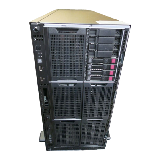
HPE ProLiant ML350 Gen9 Server
User Guide
Abstract
This document is for the person who installs, administers, and troubleshoots servers and storage systems. Hewlett Packard Enterprise
assumes you are qualified in the servicing of computer equipment and trained in recognizing hazards in products with hazardous energy
levels.
Part Number: 781896-005
October 2016
Edition: 5
Advertisement
Table of Contents

Related Manuals for HPE ProLiant ML350 Gen9


Summary of Contents for HPE ProLiant ML350 Gen9
-
Page 1: User Guide
HPE ProLiant ML350 Gen9 Server User Guide Abstract This document is for the person who installs, administers, and troubleshoots servers and storage systems. Hewlett Packard Enterprise assumes you are qualified in the servicing of computer equipment and trained in recognizing hazards in products with hazardous energy levels. - Page 2 Copyright 2014, 2016 Hewlett Packard Enterprise Development LP The information contained herein is subject to change without notice. The only warranties for Hewlett Packard Enterprise products and services are set forth in the express warranty statements accompanying such products and services. Nothing herein should be construed as constituting an additional warranty.
-
Page 3: Table Of Contents
Contents Component identification .......................... 7 Front panel components ............................7 Front panel LEDs and buttons ..........................10 UID button functionality ..........................11 Front panel LEDs power fault codes ......................11 Rear panel components ............................11 Rear panel LEDs ..............................12 Systems Insight Display LEDs .......................... - Page 4 Storage controller options ............................62 Installing a Flexible Smart Array Controller option ..................62 Installing an HPE Host Bus Adapter ......................65 Installing a storage controller and FBWC module option ................69 Installing an HPE Smart Storage Battery ....................74 Installing a SAS Expander option ........................
- Page 5 Power supply backplane cabling .......................... 139 Drive cage power cabling ............................. 141 Embedded SATA cabling ............................. 143 HPE Flexible Smart Array Controller Mini-SAS cabling ..................144 HPE Smart Array Controller Mini-SAS Y-cabling ....................144 SAS Expander cabling ............................146 Express bay cabling ............................. 148 M.2 SSD cabling ..............................
- Page 6 Ukraine RoHS material content declaration ....................169 Electrostatic discharge .......................... 170 Preventing electrostatic discharge ........................170 Grounding methods to prevent electrostatic discharge ..................170 Specifications ............................171 Environmental specifications ..........................171 Server specifications ............................171 Power supply specifications ..........................172 Hot-plug power supply calculations ........................
-
Page 7: Component Identification
Component identification Front panel components • SFF model (tower orientation) Item Description SFF SAS/SATA drives Serial label pull tab* Drive cage bays Optical drive bay Media/drive cage bays USB 2.0 connectors (2) *The serial label pull tab is double-sided. One side shows the server serial number, and the other side shows the default iLO account information. - Page 8 • SFF model (rack orientation) Item Description SFF SAS/SATA drives Serial label pull tab* Drive cage bays Optical drive bay Media/drive cage bays Systems Insight Display bay USB 2.0 connectors (2) *The serial label pull tab is double-sided. One side shows the server serial number, and the other side shows the default iLO account information.
- Page 9 Item Description Media/drive cage bay Drive cage bay Serial label pull tab* LFF SAS/SATA drives Optical drive bay USB 2.0 connectors (2) *The serial label pull tab is double-sided. One side shows the server serial number, and the other side shows the default iLO account information.
-
Page 10: Front Panel Leds And Buttons
If the health LED indicates a degraded or critical state, review the system IML ("Integrated Management Log" on page 152) or use iLO ("HPE iLO" on page 150) to review the system health status. NIC status LED Solid green = Link to network... -
Page 11: Uid Button Functionality
11)." UID button functionality The UID button can be used to display the HPE ProLiant Pre-boot Health Summary when the server will not power on. For more information, see the HPE iLO 4 User Guide on the Hewlett Packard Enterprise website (http://www.hpe.com/info/ilo/docs). -
Page 12: Rear Panel Leds
Item Description Slot 4 PCIe3 x8 (4, 1) (processor 1) Padlock hole NIC connector 2 Kensington lock slot NIC connector 4 Serial connector Slot 5 PCIe2 x8 (4, 1) (processor 2) Slot 6 PCIe3 x16 (16, 8, 4, 1) (processor 2) Slot 7 PCIe3 x8 (4, 1) (processor 2) Slot 8 PCIe3 x16 (16, 8, 4, 1) (processor 2) Slot 9 PCIe3 x8 (4, 1) (processor 2) -
Page 13: Systems Insight Display Leds
8 flashes per second = iLO manual reboot sequence in progress Off = Deactivated Systems Insight Display LEDs The HPE SID LEDs represent the system board layout. To view the LEDs, see "Using the Systems Insight Display (on page 41)." Item Description... -
Page 14: Systems Insight Display Led Combinations
Item Description Status DIMM LEDs Amber = DIMM error Off = Normal NIC LED Solid green = Link to network Flashing green (1 Hz/cycle per sec) = Network active Off = No network activity All other LEDs Off = Normal On = Failed Systems Insight Display LED combinations When the health LED on the front panel illuminates either amber or red, the server is experiencing a... -
Page 15: System Board Components
Systems Insight System power Health LED Status Display LED and color — Amber Power cap has been exceeded. Power cap (flashing amber) — Green Power is available. Power cap (green) IMPORTANT: If more than one DIMM slot LED is illuminated, further troubleshooting is required. -
Page 16: Nmi Functionality
To force the system to invoke the NMI handler and generate a crash dump log, do one of the following: • Use the iLO Virtual NMI feature. • Short the NMI header ("System board components" on page 15). For more information, see the Hewlett Packard Enterprise website (http://www.hpe.com/support/NMI-CrashDump). Component identification 16... -
Page 17: Dimm Slots
DIMM slots DIMM slots are numbered sequentially (1 through 12) for each processor. The supported AMP modes use the letter assignments for population guidelines. The arrow points to the front of the server. System maintenance switch Position Default Function Off = iLO security is enabled. On = iLO security is disabled. -
Page 18: Power Supply Backplane Connectors
Position Default Function Off = Power-on password is enabled. On = Power-on password is disabled. Off = No function On = ROM reads system configuration as invalid. Off = Set default boot mode to UEFI. On = Set default boot mode to legacy. —... -
Page 19: Device Numbering
• x4 power supply backplane Connector Description GPU Power cable connector (optional) GPU Power cable connector (optional) Drive boxes 1,2,3 backplane power cable connector Drive boxes 4,5,6 backplane power cable connector 2x4 System board power cable connector 2x12 System board power cable connector 2x20 System board signal cable connector GPU Power cable connector (optional) GPU Power cable connector (optional) - Page 20 Tower orientation Rack orientation • 24 LFF drives Component identification 20...
- Page 21 Tower orientation Rack orientation • SAS Expander One SAS expander configuration with SFF drives Component identification 21...
- Page 22 — Tower orientation — Rack orientation One SAS expander configuration with LFF drives Component identification 22...
- Page 23 — Tower orientation — Rack orientation Two SAS expanders configuration with SFF drives Component identification 23...
- Page 24 — Tower orientation — Rack orientation • Media bay Component identification 24...
- Page 25 SFF Media bay and 32 SFF drives LFF Media bay and 16 LFF drives • NVMe SSD Express bay NVMe SSD Express bay installed in box 1 and 8 SFF drives Component identification 25...
-
Page 26: Hot-Plug Drive Led Definitions
NVMe SSD Express bay installed in box 4 and 8 SFFdrives NVMe SSD Express bay and 40 SFF drives Hot-plug drive LED definitions Item Status Definition Locate Solid blue The drive is being identified by a host application. Flashing blue The drive carrier firmware is being updated or requires an update. -
Page 27: Nvme Ssd Components
Item Status Definition Removing the drive does not cause a logical drive to fail. Drive status Solid green The drive is a member of one or more logical drives. Flashing green The drive is rebuilding or performing a RAID migration, strip size migration, capacity expansion, or logical drive extension, or is erasing. -
Page 28: Hot-Plug Fans
Item Component Status Definition Do Not Remove Releases the release lever for removal and insertion. — button Upon NVMe SSD insertion, an LED initiation sequence will be visible - lighting each LED in the carrier in sequence from left to right. - Page 29 For a single-processor redundant configuration, six fans and one blank is required in specific fan bays for redundancy. A fan failure causes a loss of redundancy. A second fan failure causes an orderly shutdown of the server. Installing more than the required number of fans in a single-processor configuration is not a supported configuration.
-
Page 30: Operations
Operations Powering up the server To power up the server, press the Power On/Standby button. Power down the server Before powering down the server for any upgrade or maintenance procedures, perform a backup of critical server data and programs. IMPORTANT: When the server is in standby mode, auxiliary power is still being provided to the system. -
Page 31: Remove The Security Bezel (Optional)
Remove the security bezel (optional) Unlock the security bezel, press the latch on the security bezel, and then remove the security bezel. Remove the tower bezel The tower configuration server has a removable bezel that must be unlocked and opened before accessing the drives. -
Page 32: Remove The Access Panel
Close the bezel. Using the key provided with the server, lock the bezel with a counterclockwise turn. Remove the access panel WARNING: To reduce the risk of personal injury from hot surfaces, allow the drives and the internal system components to cool before touching them. CAUTION: To prevent damage to electrical components, take the appropriate anti-static precautions before beginning any installation, removal, or replacement procedure. -
Page 33: Install The Access Panel
Open the access panel latch, slide the access panel to the rear of the chassis, and then remove the access panel. If the access panel latch is locked, use a T-15 Torx screwdriver to unlock the latch. Install the access panel Place the access panel on top of the server with the hood latch open. -
Page 34: Extend The Server From The Rack
Power up the server ("Powering up the server" on page 30). Do one of the following: For tower models, install the tower bezel (on page 31). For rack models, if removed, install the security bezel ("Security bezel option" on page 50). Extend the server from the rack WARNING: To reduce the risk of personal injury or equipment damage, be sure that the rack is adequately stabilized before extending a component from the rack. -
Page 35: Install The Air Baffle
For tower models, open and remove the tower bezel ("Remove the tower bezel" on page 31). For rack models, if installed, remove the security bezel ("Remove the security bezel (optional)" on page 31). Power down the server (on page 30). Remove all power: Disconnect each power cord from the power source. -
Page 36: Remove A Fan
To install the component: Install the air baffle. Install the access panel (on page 33). Do one of the following: If the server is in a tower configuration, return the server to an upright position. If the server is in a rack configuration, slide the server into the rack. Connect each power cord to the server. -
Page 37: Remove The Fan Cage
Remove the access panel (on page 32). Locate the fan to be removed ("Hot-plug fans" on page 28). Remove a fan. CAUTION: Do not operate the server for long periods with the access panel open or removed. Operating the server in this manner results in improper airflow and improper cooling that can lead to thermal damage. -
Page 38: Install The Fan Cage
For rack models, extend the server from the rack (on page 34). Remove the access panel (on page 32). Remove the air baffle (on page 34). Remove the fan cage. Install the fan cage Install the fan cage. Install the access panel (on page 33). Do one of the following: If the server is in a tower configuration, return the server to an upright position. -
Page 39: Remove The Optical Drive
Do one of the following: For tower models, install the tower bezel (on page 31). For rack models, install the security bezel ("Security bezel option" on page 50). Remove the optical drive The server supports both DVD-ROM and DVD-RW drives. Do one of the following: For tower models, open and remove the tower bezel ("Remove the tower... - Page 40 Remove the component drive cage blank: WARNING: To reduce the risk of personal injury from an electrical hazard, do not remove more than one drive cage at a time. SFF model LFF model — To remove the drive cage blank from outside the server, use a flathead screwdriver to remove the blank from the box.
-
Page 41: Using The Systems Insight Display
To remove the drive cage blank from inside the server, push out the drive blank from inside. Using the Systems Insight Display The HPE Systems Insight Display (SID) is only available as an option for rack configurations. Remove the security bezel ("Remove the security bezel... - Page 42 After the display fully ejects, rotate the display to view the LEDs. For descriptions of the Systems Insight Display LEDs, see "Systems Insight Display LEDs (on page 13)." Operations 42...
-
Page 43: Setup
Setup Optional services Delivered by experienced, certified engineers, HPE support services help you keep your servers up and running with support packages tailored specifically for HPE ProLiant systems. HPE support services let you integrate both hardware and software support into a single package. A number of service level options are available to meet your business and IT needs. -
Page 44: Temperature Requirements
(95°F). The temperature in the room where the rack is located must not exceed 35°C (95°F). For information on ambient operating temperature support above 35°C, see the Hewlett Packard Enterprise website (http://www.hpe.com/servers/ASHRAE). CAUTION: To reduce the risk of damage to the equipment when installing third-party options: •... -
Page 45: Electrical Grounding Requirements
For more information on the hot-plug power supply and calculators to determine server power consumption in various system configurations, see the Hewlett Packard Enterprise Power Advisor website (http://www.hpe.com/info/poweradvisor/online). Electrical grounding requirements The server must be grounded properly for proper operation and safety. In the United States, you must install the equipment in accordance with NFPA 70, 1999 Edition (National Electric Code), Article 250, as well as any local and regional building codes. -
Page 46: Server Warnings And Cautions
CAUTION: If the DC connection exists between the earthed conductor of the DC supply circuit and the earthing conductor at the server equipment, the following conditions must be met: • This equipment must be connected directly to the DC supply system earthing electrode conductor or to a bonding jumper from an earthing terminal bar or bus to which the DC supply system earthing electrode conductor is connected. -
Page 47: Installing Hardware Options
• Server • Power cord • Tower feet • Hardware documentation and software products In addition to the supplied items, you might need: • Hardware options • Operating system or application software • Torx T-15, Philips #2, and flathead screwdriver Installing hardware options Install any hardware options before initializing the server. -
Page 48: Installing The Server Into A Rack
If you do not need to modify the server configuration and are ready to install the system software, press the F10 key to access Intelligent Provisioning. For more information on automatic configuration, see the UEFI documentation on the Hewlett Packard Enterprise website (http://www.hpe.com/info/ProLiantUEFI/docs). Setup 48... -
Page 49: Installing The Operating System
Failure to observe UEFI requirements for ProLiant Gen9 servers can result in errors installing the operating system, failure to recognize boot media, and other boot failures. For more information on these requirements, see the HPE UEFI Requirements on the Hewlett Packard Enterprise website (http://www.hpe.com/info/ProLiantUEFI/docs). -
Page 50: Hardware Options Installation
Product QuickSpecs For more information about product features, specifications, options, configurations, and compatibility, see the product QuickSpecs on the Hewlett Packard Enterprise website (http://www.hpe.com/info/qs). Introduction If more than one option is being installed, read the installation instructions for all the hardware options and identify similar steps to streamline the installation process. - Page 51 WARNING: This server is heavy. To reduce the risk of personal injury or damage to the equipment: • Observe local occupational health and safety requirements and guidelines for manual material handling. • Get help to lift and stabilize the product during installation or removal, especially when the product is not fastened to the rails.
- Page 52 Remove the server base feet. Remove all screws securing the base cover to the chassis. Slide the base cover toward the rear of the server, and then remove the base cover. Hardware options installation 52...
- Page 53 Install the server base blank covers over the server base feet holes. Turn the server over, and then remove the access panel (on page 32). Remove the air baffle (on page 34). Remove the fan cage (on page 37). Locate the system maintenance switch on the system board. Configure position 10 of the system maintenance switch to ON for a rack configuration.
- Page 54 Insert and completely tighten the 3 long silver T-15 screws on the upper side of each rack bezel ear. Insert and completely tighten the 2 short black T-15 screws on the lower side of each rack bezel ear. Install the front bezel hinge covers. Hardware options installation 54...
- Page 55 Remove the handle hole covers from the chassis, and retain the screws. Install the rack server handles. Install the fan cage (on page 38). Install the air baffle (on page 35). Hardware options installation 55...
-
Page 56: Systems Insight Display Option
Pay particular attention to the plug, electrical outlet, and the point where the cord extends from the server. Systems Insight Display option The HPE Systems Insight Display (SID) is only available as an option for rack configurations. If installed, remove the security bezel ("Remove the security bezel (optional)"... - Page 57 Extend the server from the rack (on page 34). Remove the access panel (on page 32). Remove the air baffle (on page 34). Remove the fan cage (on page 37). CAUTION: When routing cables, always be sure that the cables are not in a position where they can be pinched or crimped.
-
Page 58: Drive Options
62). For more information about product features, specifications, options, configurations, and compatibility, see the product QuickSpecs on the Hewlett Packard Enterprise website (http://www.hpe.com/info/qs). Drive installation guidelines When adding drives to the server, observe the following general guidelines: •... -
Page 59: Removing A Drive Blank
Removing a drive blank Do one of the following: For tower models, open and remove the tower bezel (on page 31). For rack models, if installed, remove the security bezel ("Remove the security bezel (optional)" on page 31). Remove the drive blank. Installing a hot-plug SAS or SATA drive WARNING: To reduce the risk of injury from electric shock, do not install more than one drive carrier at a time. -
Page 60: Removing A Hot-Plug Sas Or Sata Drive
NVMe drives are supported on this server when the Express bay kit is installed. For installation instructions, see "Installing the HPE NVMe Express bay (on page 83)." For more information on which bays support NVMe drives, see "Device numbering (on page 19)."... - Page 61 To install the drives: CAUTION: To prevent improper cooling and thermal damage, do not operate the server or the enclosure unless all drive and device bays are populated with either a component or a blank. Back up all server data. Do one of the following: For tower models, open and remove the tower bezel ("Remove the tower...
-
Page 62: Storage Controller Options
Storage controller options The server includes an embedded Dynamic Smart Array B140i Controller. For more information about the controller and its features, see the HPE Dynamic Smart Array B140i RAID Controller User Guide on the Hewlett Packard Enterprise website (http://www.hpe.com/info/smartstorage/docs). - Page 63 For rack models, if installed, remove the security bezel ("Remove the security bezel (optional)" on page 31). Power down the server (on page 30). Remove all power: Disconnect each power cord from the power source. Disconnect each power cord from the server. Do one of the following: For tower models, place the server on a flat, level surface with the access panel facing up.
- Page 64 Install the Flexible Smart Array Controller. Connect the Mini-SAS cables from the drive backplane to the Flexible Smart Array Controller. SFF configuration Hardware options installation 64...
-
Page 65: Installing An Hpe Host Bus Adapter
For tower models, install the tower bezel (on page 31). For rack models, install the security bezel ("Security bezel option" on page 50). Installing an HPE Host Bus Adapter NOTE: Smart Array controllers are not supported in PCIe slot 5. To install the component: Back up all server data. - Page 66 Do one of the following: For tower models, place the server on a flat, level surface with the access panel facing up. For rack models, extend the server from the rack (on page 34). Remove the access panel (on page 32). Remove the air baffle (on page 34).
- Page 67 — SFF configuration — LFF configuration Cable routing if a second processor is installed and the host bus adapter is installed in PCIe slot 6 to 9 Hardware options installation 67...
- Page 68 — SFF configuration — LFF configuration Install the fan cage (on page 38). Install the air baffle (on page 35). Install the access panel (on page 33). Do one of the following: If the server is in a tower configuration, return the server to an upright position. If the server is in a rack configuration, slide the server into the rack.
-
Page 69: Installing A Storage Controller And Fbwc Module Option
Installing a storage controller and FBWC module option NOTE: Smart Array controllers are not supported in PCIe slot 5. An HPE Smart Array Controller Mini-SAS cable option is required to install a Smart Array Controller option. To install the component: Back up all server data. - Page 70 Install the cache module on the storage controller. Install the Smart Array controller. Select an available expansion slot from PCIe slots 1 to 4 or 6 to 9, and then remove the slot cover of the corresponding slot. If installing the HBA in slots 6-9, a second processor option must be installed first. See "Processor option (on page 90)."...
- Page 71 Install the Smart Array controller. Verify that the board is firmly seated in the slot. Close the slot retainer or tighten the screw to secure the controller. Connect the Mini-SAS Y-cable: Connect the common end of the Mini-SAS Y-cable to the Smart Array controller. Route the two ends of the Mini-SAS Y-cable through the cable management clips, and then connect them to the drive backplane.
- Page 72 — LFF configuration Cable routing if a second processor is installed and the Smart Array controller is installed in PCIe slot 6 to 9 — SFF configuration Hardware options installation 72...
- Page 73 — LFF configuration If the cache module is installed on the Smart Array controller, connect the cache module backup power cable to the system board. There are two FBWC module backup power cable connectors available for each group of PCIe connectors.
-
Page 74: Installing An Hpe Smart Storage Battery
For more information on the Smart Array storage controllers, select the relevant user documentation on the Hewlett Packard Enterprise website (http://www.hpe.com/info/smartstorage/docs). To configure arrays, see the HPE Smart Storage Administrator User Guide on the Hewlett Packard Enterprise website (http://www.hpe.com/info/smartstorage/docs). Installing an HPE Smart Storage Battery For more information about product features, specifications, options, configurations, and compatibility, see the product QuickSpecs on the Hewlett Packard Enterprise website (http://www.hpe.com/info/qs). - Page 75 Do one of the following: For tower models, open and remove the tower bezel ("Remove the tower bezel" on page 31). For rack models, if installed, remove the security bezel ("Remove the security bezel (optional)" on page 31). Power down the server (on page 30). Remove all power: Disconnect each power cord from the power source.
-
Page 76: Installing A Sas Expander Option
Expanders can only be installed in SFF models. Check that you have installed the latest firmware for the controllers, HBAs, and the expander card. To download the latest firmware, see the Hewlett Packard Enterprise website (http://www.hpe.com/support/hpesc). To install the component: Back up all server data. - Page 77 Remove all power: Disconnect each power cord from the power source. Disconnect each power cord from the server. Do one of the following: For tower models, place the server on a flat, level surface with the access panel facing up. For rack models, extend the server from the rack (on page 34).
- Page 78 Connect the HBA to Expander Mini-SAS X cable (788456-001) from the Host Bus Adapter to the Expander card. Connect port 1 to port 1 and port 2 to port 2. Connect the Smart Array to Expander Mini-SAS Y cable (779300-001) from the Smart Array controller to the Expander card ports 1 and 2.
- Page 79 Connect each end of the three Mini-SAS X cables to the matching port on each drive box backplane. Connect port 1 to port 1 and port 2 to port 2 for each cable set. Install the storage controller into PCIe slot 1 or 3. Install the Expander card into PCIe slot 2.
-
Page 80: Installing A Second Sas Expander Card
50). Installing a second SAS Expander card The second SAS Expander card must be used with an HPE Smart Array P840 controller, first SAS Expander, second processor, and the x4 redundant power supply options all installed in the server. - Page 81 Connect the 1000 mm Smart Array to the Expander Mini-SAS Y cable (778559-001) from the P840 Smart Array controller (port 1I) to the second SAS Expander card ports 1 and 2. Connect the three Expander to backplane Mini-SAS X cables (788453-001, 788454-001, 788455-001) from the second SAS Expander card to each backplane according to the table below: SAS Expander First SAS...
- Page 82 Remove the expansion slot retainer cover and the slot blank. Install the second SAS Expander card into PCIe slot 9. Close the slot retainer cover. Route the cables and secure them under the cable clips. Install the fan cage (on page 38). Install the air baffle (on page 35).
-
Page 83: Sas Expander Configurations
An x4 Redundant Power Supply kit is required when four or more drive cages, including the Express bay drive kit, are installed in the server. The Express drive bay supports 400 GB, 800 GB, 1.2 TB NVMe SSD drives. The HPE NVMe Express drive bay may be installed in bay 1 or 4 of an SFF model. - Page 84 Install the Express bay drive cage assembly: Remove the drive cage blank from box 1 or 4. Install the Express bay drive cage and backplane assembly. Connect the 2x4 connector of the power Y-cable to the Express bay drive cage backplane. Connect the other two ends of the power Y-cable to the cable connectors from the server power supply backplane.
- Page 85 Remove the expansion slot retainer cover and the slot blank. Install the Express bay bridge card. Close the PCI slot cover retainer. Connect the Express bay data cables to the corresponding ports on the Express bay bridge card. Hardware options installation 85...
- Page 86 — Cable routing if the Express bay bridge card is installed in PCIe slot 3 — Cable routing if a second processor is installed and the express bay bridge card is installed in PCIe slot 6 or 8 To ensure proper thermal cooling, adhere airflow covers to the outside of all drive cage blanks. Remove all drive cage blanks.
-
Page 87: Optical Drive Option
Install an airflow cover onto each drive cage blank, leaving only the top two rows of venting exposed. Install the drive cage blanks. Install the NVMe SSD drives ("Installing NVMe drives" on page 60). Install the fan cage (on page 38). Install the air baffle (on page 35). - Page 88 For rack models, extend the server from the rack (on page 34). Remove the access panel (on page 32). Using a Philips #1 screwdriver, remove the 9.5 mm optical drive rear side carrier. Remove the optical drive blank from the front panel: Open the latch securing the drive blank.
- Page 89 Remove the screw from the optical drive carrier. Remove the optical drive carrier. Install the 9.5mm optical drive into the optical drive carrier. Tighten the screws on the optical drive carrier. Connect the SATA and power cables to the optical drive. LFF configuration Hardware options installation 89...
-
Page 90: Processor Option
To upgrade from E5-2600 v3 processor(s) to E5-2600 v4 processor(s), see Customer Advisory (c04849981) (http://h20564.www2.hpe.com/hpsc/doc/public/display?docId=c04849981). For more information about product features, specifications, options, configurations, and compatibility, see the product QuickSpecs on the Hewlett Packard Enterprise website (http://www.hpe.com/info/qs). Processor installation cautions The server supports single-processor and dual-processor operations. -
Page 91: Installing A Second Processor
CAUTION: To prevent possible server malfunction and damage to the equipment, multiprocessor configurations must contain processors with the same part number. IMPORTANT: If installing a processor with a faster speed, update the system ROM before installing the processor. IMPORTANT: Processor socket 1 must be populated at all times or the server does not function. - Page 92 Remove the clear processor socket cover. Retain the processor socket cover for future use. CAUTION: THE PINS ON THE SYSTEM BOARD ARE VERY FRAGILE AND EASILY DAMAGED. To avoid damage to the system board, do not touch the processor or the processor socket contacts.
- Page 93 Press and hold the processor retaining bracket in place, and then close each processor locking lever. Press only in the area indicated on the processor retaining bracket. CAUTION: Close and hold down the processor cover socket while closing the processor locking levers.
- Page 94 Finish the installation by completely tightening the screws in the same sequence. Install the air baffle (on page 35). Remove the fan blank from fan bay 1. Hardware options installation 94...
-
Page 95: Redundant Fan Option
To provide sufficient airflow to the system if a fan fails, the server supports redundant fans. For more information about product features, specifications, options, configurations, and compatibility, see the product QuickSpecs on the Hewlett Packard Enterprise website (http://www.hpe.com/info/qs). To install the component:... - Page 96 Remove the access panel (on page 32). Remove the fan blank. Install the fan, making sure that the fan clicks into place. Hardware options installation 96...
-
Page 97: Memory Options
RDIMM, the information applies to that type only. All memory installed in the server must be of the same type. Memory-processor compatibility information For the latest memory configuration information, see the product QuickSpecs on the Hewlett Packard Enterprise website (http://www.hpe.com/info/qs). DIMM types Hardware options installation 97... - Page 98 • Intel Xeon E5-2600 v3 processors are optimized for: Single-rank and dual-rank PC4-2133 (DDR4-2133) RDIMMs operating at up to 2133 MT/s Dual-rank and quad-rank PC4-2133 (DDR4-2133) LRDIMMs operating at up to 2133 MT/s • Intel Xeon E5-2600 v4 processors are optimized for: Single-rank and dual-rank PC4-2400T (DDR4-2400) RDIMMs operating at up to 2400 MT/s Dual-rank and quad-rank PC4-2400T (DDR4-2400) LRDIMMs operating at up to 2400 MT/s DIMM specifications...
-
Page 99: Smartmemory
Maximum memory capacity is a function of DIMM capacity, number of installed DIMMs, memory type, and number of installed processors. Maximum memory capacity - Intel Xeon E5-2600 v3 processor installed DIMM type DIMM rank Capacity (GB) Maximum Maximum capacity for one capacity for two processor (GB) processors (GB) -
Page 100: Single-, Dual-, And Quad-Rank Dimms
Memory Slot number Slot number Population order subsystem (Processor 2) (Processor 1) channel For the location of the slot numbers, see "DIMM slots (on page 17)." This multi-channel architecture provides enhanced performance in Advanced ECC mode. This architecture also enables Online Spare Memory modes. DIMM slots in this server are identified by number and by letter. -
Page 101: Memory Configurations
AMP mode is not supported by the installed DIMM configuration, the server boots in Advanced ECC mode. For more information, see the HPE UEFI System Utilities User Guide for HPE ProLiant Gen9 Servers on the Hewlett Packard Enterprise website (http://www.hpe.com/info/ProLiantUEFI/docs). -
Page 102: General Dimm Slot Population Guidelines
• DIMMs should be populated starting farthest from the processor on each channel. For more information about server memory, see the Hewlett Packard Enterprise website (http://www.hpe.com/info/memory). Advanced ECC population guidelines For Advanced ECC mode configurations, observe the following guidelines: •... -
Page 103: Identifying The Processor Type
• Each populated channel must have a spare rank. A single dual-rank DIMM is not a valid configuration. Mirrored Memory population guidelines For Mirrored Memory mode configurations, observe the following guidelines: • Observe the general DIMM slot population guidelines (on page 102). •... -
Page 104: Sff Media Cage Option
(on page 14)." SFF media cage option For more information about product features, specifications, options, configurations, and compatibility, see the product QuickSpecs on the Hewlett Packard Enterprise website (http://www.hpe.com/info/qs). To install the component: Do one of the following: For tower models, open and remove the tower bezel ("Remove the tower... - Page 105 Remove the blanks from boxes 1 and 2. If the server is installed in a rack and has the SID option installed, then extend the SID module. Hardware options installation 105...
- Page 106 Remove the panel covers above boxes 1 and 2. Remove the divider between boxes 1 and 2. Hardware options installation 106...
- Page 107 Install the media cage. If extended, slide the Systems Insight Display back into the slot. Install the media device. Connect the SFF media power cable. Connect the data cable to the media device. Hardware options installation 107...
-
Page 108: Lff Media Cage Option
50). LFF media cage option For more information about product features, specifications, options, configurations, and compatibility, see the product QuickSpecs on the Hewlett Packard Enterprise website (http://www.hpe.com/info/qs). To install the component: Back up all server data. Do one of the following: For tower models, open and remove the tower bezel ("Remove the tower... - Page 109 For tower models, place the server on a flat, level surface with the access panel facing up. For rack models, extend the server from the rack (on page 34). Remove the access panel (on page 32). Remove the air baffle (on page 34). Remove the fan cage (on page 37).
- Page 110 Connect the LFF media power cable. Connect the data cable to the media device. Cable routing to connect a SATA device Install the fan cage (on page 38). Install the air baffle (on page 35). Install the access panel (on page 33). Do one of the following: If the server is in a tower configuration, return the server to an upright position.
-
Page 111: Gpu Power Cable Option
For more information about product features, specifications, options, configurations, and compatibility, see the product QuickSpecs on the Hewlett Packard Enterprise website (http://www.hpe.com/info/qs). To install a third 150W GPU, a third power supply must be installed.If more than two power supplies are needed, then the x4 Redundant power supply option ("x4 Redundant Power Supply backplane... - Page 112 Using the system board tray handles, slide the tray forward, and then remove the system board. Connect the graphic card power cable to the nearest server graphic card power connector on the power supply backplane. Hardware options installation 112...
- Page 113 Install the system board assembly and tighten the two thumbscrews. Open the PCI retainer latch. Hardware options installation 113...
- Page 114 To install a single-width graphic card, remove one PCI blank. To install a double-width graphic card, remove two PCI blanks. Connect the graphic card power cable to the graphic card. Hardware options installation 114...
- Page 115 Install the graphic card in an x16 PCI expansion slot. Close the PCIe retainer latch. Install the fan cage (on page 38). Install the air baffle (on page 35). Install the access panel (on page 33). Do one of the following: If the server is in a tower configuration, return the server to an upright position.
-
Page 116: Eight-Bay Sff Drive Cage Option
Eight-bay SFF drive cage option Install additional SFF drive cages option in this order: box 5, 4, 3, 2, and 1. For more information on drive and box numbering, see "Device numbering (on page 19)." If more than 3 SFF drive cages (including an NVMe Express bay) are used, then the x4 Redundant power supply option ("x4 Redundant Power Supply backplane option"... - Page 117 Using the two T-15 screws, secure the rear side of the drive cage. Connect the Mini-SAS cable from a storage controller to the drive backplane: Cable routing if the storage controller is installed in PCIe slot 1 to 4. Hardware options installation 117...
- Page 118 Cable routing if second processor is installed and the storage controller is installed in slot 6 to 9. Connect the power cable to the drive backplane. Install the drives into the drive cage. Populate any unused drive bays with a drive blank. Install the fan cage (on page 38).
-
Page 119: Eight-Bay Lff Drive Backplane Option
For tower models, install the tower bezel (on page 31). For rack models, install the security bezel ("Security bezel option" on page 50). Eight-bay LFF drive backplane option The server ships with a drive backplane and cables for data and power installed for box 3. Install a second optional backplane in box 2 and then a third optional backplane in box 1. - Page 120 Connect the Mini-SAS cable from the storage controller to the drive backplane. Connect either the box 1 or box 2 power cable to the new backplane. Install drives into the drive cage. Populate any unused drive bays with a drive blank. Install the fan cage (on page 38).
-
Page 121: M.2 Ssd Enablement Board Option
For tower models, install the tower bezel (on page 31). For rack models, install the security bezel ("Security bezel option" on page 50). M.2 SSD enablement board option The M.2 enablement board is only supported in PCIe slot 1. Installing an M.2 SSD enablement board Back up all server data. -
Page 122: Installing An Ssd Module
Connect and route the SATA cables from the M.2 SSD enablement board to the system board. Install the air baffle (on page 35). Install the access panel (on page 33). Do one of the following: If the server is in a tower configuration, return the server to an upright position. If the server is in a rack configuration, slide the server into the rack. -
Page 123: Dual 8Gb Microsd Enterprise Midline Usb Device
IMPORTANT: For management and monitoring of the SSD modules, use the HPE Smart Storage Administrator (http://www.hpe.com/servers/ssa). Install the SSD module on the M.2 SSD enablement board. Install the M.2 SSD Enablement Board in slot one of the PCIe riser cage ("Installing an M.2 SSD... -
Page 124: Power Supply Options
Power supply options Hot-plug power supply module CAUTION: All power supplies installed in the server must have the same output power capacity. Verify that all power supplies have the same part number and label color. The system becomes unstable and may shut down when it detects mismatched power supplies. CAUTION: To prevent improper cooling and thermal damage, do not operate the server unless all bays are populated with either a component or a blank. -
Page 125: X4 Redundant Power Supply Backplane Option
Route the power cord. Use best practices when routing power cords and other cables. A cable management arm is available to help with routing. To obtain a cable management arm, contact a Hewlett Packard Enterprise authorized reseller. Connect the power cord to the AC power source. x4 Redundant Power Supply backplane option The x4 Redundant Power Supply backplane option must be installed when more that 3 SFF drive cages (including an NVMe Express bay) are used. - Page 126 Using the system board tray handles, slide the tray forward, and then remove the system board. Remove all power supplies. Remove the two bay power supply backplane: Disconnect all cables connected to the power supply backplane. Retain all the cables for reconnecting them to the x4 RPS backplane. Remove the two screws securing the backplane to the chassis.
- Page 127 Tighten the three screws on the backplane. Connect all cables to the x4 RPS backplane board. Route the x4 RPS backplane cables. Install the system board. Connect all the cables disconnected from the system board. Install the expansion boards. Install the fan cage. Hardware options installation 127...
- Page 128 Remove the cover over power supply slots 3 and 4. Install all power supplies. Install a power supply blank into any unpopulated power supply bays. Install the fan cage (on page 38). Install the air baffle (on page 35). Install the access panel (on page 33). Do one of the following: If the server is in a tower configuration, return the server to an upright position.
-
Page 129: Power Supply Modes
If more than three SFF hard drive cages are installed, then the X4 RPS Enablement Kit must be installed in order to have enough drive power connectors. The x4 Redundant Power Supply Enablement (RPS) Kit only supports the HPE 800 W and HPE 1400 W Flex Slot Platinum hot-plug power supplies. -
Page 130: Hpe Trusted Platform Module Option
HPE Trusted Platform Module option For more information about product features, specifications, options, configurations, and compatibility, see the product QuickSpecs on the Hewlett Packard Enterprise website (http://www.hpe.com/info/qs). Use these instructions to install and enable a TPM on a supported server. This procedure includes three sections: Installing the Trusted Platform Module board. -
Page 131: Installing The Trusted Platform Module And Security Rivet
• Do not remove an installed TPM. Once installed, the TPM becomes a permanent part of the system board. • When installing or replacing hardware, Hewlett Packard Enterprise service providers cannot enable the TPM or the encryption technology. For security reasons, only the customer can enable these features. - Page 132 Install the TPM board. Press down on the connector to seat the board ("System board components" on page 15). Install the TPM security rivet by pressing the rivet firmly into the system board. Install the air baffle (on page 35). Install the access panel (on page 33).
-
Page 133: Retaining The Recovery Key/Password
For more information on firmware updates and hardware procedures, see the HP Trusted Platform Module Best Practices White Paper on the Hewlett Packard Enterprise website (http://www.hpe.com/support/hpesc). For more information on adjusting TPM usage in BitLocker™, see the Microsoft website (http://technet.microsoft.com/en-us/library/cc732774.aspx). -
Page 134: Cabling
For information on cabling peripheral components, refer to the white paper on high-density deployment at the Hewlett Packard Enterprise website (http://www.hpe.com/info/servers). CAUTION: When routing cables, always be sure that the cables are not in a position where they can be pinched or crimped. -
Page 135: Optical Device Cabling
• LFF media cage data cabling Optical device cabling • LFF configuration Item Description ODD signal cable to SATA port 5 Power supply backplane cable ODD power cable Cabling 135... -
Page 136: Front I/O Module Cabling
• SFF configuration Item Description ODD signal cable to SATA port 5 Power supply backplane cable ODD power cable Front I/O module cabling Item Description Ambient sensor cable Front I/O LEDs and button cable Cabling 136... -
Page 137: Systems Insight Display Cabling
Systems Insight Display cabling • SFF configuration • LFF configuration FBWC module backup power cabling The FBWC solution is a separately purchased option. This server only supports FBWC module installation when a Smart Array P-Series controller is installed. Depending on the controller option installed, the actual storage controller connectors might look different from what is shown in this section. - Page 138 • Storage controller installed in slot 1 to 4 • Storage controller installed in slot 6 to 9 Cabling 138...
-
Page 139: Hpe Smart Storage Battery Cabling
HPE Smart Storage Battery cabling Power supply backplane cabling • GPU power cabling Cabling 139... - Page 140 • x4 Power supply backplane cabling Item Description Power cables for GPU installed in slot 1 or 3 Drive cage backplane power cables System board cables Power cables for GPU installed in slot 6 or 8 • x2 power supply backplane cabling Item Description Power cables installed for GPU in slot 1 or 3...
-
Page 141: Drive Cage Power Cabling
Drive cage power cabling • LFF mode x2 power supply backplane to 3 LFF drive backplanes (supports up to 24 LFF drives) • SFF model x2 power supply backplane to 3 SFF drive cages (supports up to 24 SFF drives) Cabling 141... - Page 142 x4 power supply backplane to 3 SFF drive cages (supports up to 24 SFF drives) x4 power supply backplane to 6 SFF drive cages (supports up to 48 SFF drives) Item Description Power cable for SFF drive backplane in box 4, 5, 6, and ODD or media device Power cable for drive backplane in box 1, 2, 3 Cabling 142...
-
Page 143: Embedded Sata Cabling
Embedded SATA cabling • LFF configuration • SFF configuration Cabling 143... -
Page 144: Hpe Flexible Smart Array Controller Mini-Sas Cabling
HPE Flexible Smart Array Controller Mini-SAS cabling • SFF configuration • LFF configuration HPE Smart Array Controller Mini-SAS Y-cabling Route the two ends of the Mini-SAS Y-cable through the cable management clips, and then connect them to the drive backplane: •... - Page 145 SFF configuration LFF configuration • Cable routing if the Smart Array controller is installed in PCIe slot 6 to 9: Cabling 145...
-
Page 146: Sas Expander Cabling
SFF configuration LFF configuration SAS Expander cabling • One SAS Expander Cabling 146... - Page 147 LFF configuration SFF configuration Cabling 147...
-
Page 148: Express Bay Cabling
• Two SAS Expanders Express bay cabling • Express bay bridge card installed in PCIe slot 3 Cabling 148... -
Page 149: M.2 Ssd Cabling
• Express bay bridge card installed in PCIe slot 6 or 8 and second processor installed M.2 SSD cabling Item Description SATA cable of first M.2 SSD module SATA cable of second M.2 SSD module Cabling 149... -
Page 150: Software And Configuration Utilities
QuickSpecs on the Hewlett Packard Enterprise website (http://www.hpe.com/info/qs). HPE iLO iLO is a remote server management processor embedded on the system boards of HPE ProLiant and Synergy servers. iLO enables the monitoring and controlling of servers from remote locations. HPE iLO management is a powerful tool that provides multiple ways to configure, update, monitor, and repair servers remotely. -
Page 151: Ilo Restful Api Support
Hewlett Packard Enterprise website (http://www.hpe.com/info/privacy). iLO RESTful API support HPE iLO 4 firmware version 2.00 and later includes the iLO RESTful API. The iLO RESTful API is a management interface that server management tools can use to perform configuration, inventory, and monitoring of the ProLiant server via iLO. -
Page 152: Integrated Management Log
HPE iLO 4 supports the iLO RESTful API with ProLiant Gen8 and later servers. For more information about the iLO RESTful API, see the Hewlett Packard Enterprise website (http://www.hpe.com/info/restfulinterface/docs). Integrated Management Log The IML records hundreds of events and stores them in an easy-to-view form. The IML timestamps each event with 1-minute granularity. -
Page 153: Insight Diagnostics
ProLiant servers. This functionality supports operating systems that the server supports. For operating systems supported by the server, see the Hewlett Packard Enterprise website (http://www.hpe.com/info/supportos). If a significant change occurs between data-gathering intervals, the survey function marks the previous information and overwrites the survey data files to reflect the latest changes. -
Page 154: Service Pack For Proliant
The SPP is a comprehensive systems software (drivers and firmware) solution delivered as a single package with major server releases. This solution uses SUM as the deployment tool and is tested on all supported ProLiant servers including HPE ProLiant Gen8 and later servers. SPP allows the following operating modes: •... -
Page 155: Using Uefi System Utilities
Provisioning For more information, see the UEFI System Utilities user guide for your product on the Hewlett Packard Enterprise website (http://www.hpe.com/info/UEFI/docs). To access mobile-ready online help for the UEFI System Utilities and UEFI Shell, scan the QR code at the bottom of the screen. -
Page 156: Restoring And Customizing Configuration Settings
These features enhance the capabilities of the UEFI System Utilities. For more information, see the following documents: • UEFI Shell User Guide for HPE ProLiant Gen9 Servers on the Hewlett Packard Enterprise website (http://www.hpe.com/info/UEFI/docs) • UEFI Shell Specification on the UEFI website (http://www.uefi.org/specifications) -
Page 157: Embedded Diagnostics Option
The server automatically reboots. Utilities and features HPE Smart Storage Administrator The HPE SSA is a configuration and management tool for HPE Smart Array controllers. Starting with HPE ProLiant Gen8 servers, HPE SSA replaces ACU with an enhanced GUI and additional configuration features. -
Page 158: Automatic Server Recovery
The HPE SSA exists in three interface formats: the HPE SSA GUI, the HPE SSA CLI, and HPE SSA Scripting. Although all formats provide support for configuration tasks, some of the advanced tasks are available in only one format. Some HPE SSA features include the following: •... -
Page 159: Redundant Rom Support
The pre-OS behavior and default operation of the USB ports is configurable in the UEFI System Utilities. For more information, see the UEFI System Utilities user guide for your product on the Hewlett Packard Enterprise website (http://www.hpe.com/info/UEFI/docs). External USB functionality Hewlett Packard Enterprise provides external USB support to enable local connection of USB devices for server administration, configuration, and diagnostic procedures. -
Page 160: Keeping The System Current
For systems configured in either boot mode, update the firmware: Access the System ROM Flash Binary component for your server from the Hewlett Packard Enterprise Support Center website (http://www.hpe.com/support/hpesc). When searching for the component, always select OS Independent to locate the binary file. -
Page 161: Drivers
For more information about accessing a file system from the shell, see the UEFI Shell User Guide for HPE ProLiant Gen9 Servers on the Hewlett Packard Enterprise website (http://www.hpe.com/info/UEFI/docs). Change to the file system that contains the System ROM Flash Binary component for your server. -
Page 162: Software And Firmware
SPP, see the Hewlett Packard Enterprise website (http://www.hpe.com/servers/spp/download). To locate the drivers for a particular server, go to the Hewlett Packard Enterprise Support Center website (http://www.hpe.com/support/hpesc). Under Select your HPE product, enter the product name or number and click Go. -
Page 163: Operating Systems And Virtualization Software Support For Proliant Servers
Connect to HPE to help prevent problems and solve issues faster. By connecting, you will receive 24x7 monitoring, prefailure alerts, automatic call logging, and automatic parts dispatch. To learn more about getting connected, see the Hewlett Packard Enterprise website (http://www.hpe.com/services/getconnected). -
Page 164: Troubleshooting
• Simplified Chinese (http://www.hpe.com/support/Gen9_TSG_zh_cn) The HPE ProLiant Gen9 Troubleshooting Guide, Volume II: Error Messages provides a list of error messages and information to assist with interpreting and resolving error messages on ProLiant servers and server blades. To view the guide, select a language: •... -
Page 165: System Battery Replacement
System battery replacement If the server no longer automatically displays the correct date and time, then replace the battery that provides power to the real-time clock. Under normal use, battery life is 5 to 10 years. WARNING: The computer contains an internal lithium manganese dioxide, a vanadium pentoxide, or an alkaline battery pack. - Page 166 If the system battery is secured by a plastic outer clip, do the following: Use a small flat-bladed, nonconductive tool to carefully lift the front of the battery from the socket. Remove the battery. IMPORTANT: Replacing the system board battery resets the system ROM to its default configuration.
- Page 167 Install the access panel (on page 33). Do one of the following: If the server is in a tower configuration, return the server to an upright position. If the server is in a rack configuration, slide the server into the rack. Connect each power cord to the server.
-
Page 168: Warranty And Regulatory Information
Warranty and regulatory information Warranty information HPE ProLiant and x86 Servers and Options (http://www.hpe.com/support/ProLiantServers-Warranties) HPE Enterprise Servers (http://www.hpe.com/support/EnterpriseServers-Warranties) HPE Storage Products (http://www.hpe.com/support/Storage-Warranties) HPE Networking Products (http://www.hpe.com/support/Networking-Warranties) Regulatory information Safety and regulatory compliance For important safety, environmental, and regulatory information, see Safety and Compliance Information for Server, Storage, Power, Networking, and Rack Products, available at the Hewlett Packard Enterprise website (http://www.hpe.com/support/Safety-Compliance-EnterpriseProducts). -
Page 169: Turkey Rohs Material Content Declaration
Local representative information Kazakh: • Russia: • Belarus: • Kazakhstan: Manufacturing date: The manufacturing date is defined by the serial number. CCSYWWZZZZ (serial number format for this product) Valid date formats include: • YWW, where Y indicates the year counting from within each new decade, with 2000 as the starting point;... -
Page 170: Electrostatic Discharge
Electrostatic discharge Preventing electrostatic discharge To prevent damaging the system, be aware of the precautions you must follow when setting up the system or handling parts. A discharge of static electricity from a finger or other conductor may damage system boards or other static-sensitive devices. This type of damage may reduce the life expectancy of the device. -
Page 171: Specifications
40°C to 45°C (104°F to 113°F) at sea level with an altitude derating of 1.0°C per every 125 m (1.8°F per every 410 ft) above 900 m (2953 ft) to a maximum of 3048 m (10,000 ft). The approved hardware configurations for this system are listed on the Hewlett Packard Enterprise website (http://www.hpe.com/servers/ASHRAE). Server specifications Specification... -
Page 172: Power Supply Specifications
HPE 500W Flex Slot Platinum Hot-plug Power Supply • HPE 800W Flex Slot Platinum Hot-plug Power Supply • HPE 800W Flex Slot Titanium Plus Hot-plug Power Supply • HPE 800W Flex Slot Universal Hot-plug Power Supply • HPE 800W Flex Slot -48VDC Hot-plug Power Supply •... -
Page 173: Support And Other Resources
Hewlett Packard Enterprise Support Center. You must have an HP Passport set up with relevant entitlements. Websites • Hewlett Packard Enterprise Information Library (http://www.hpe.com/info/enterprise/docs) • Hewlett Packard Enterprise Support Center (http://www.hpe.com/support/hpesc) • Contact Hewlett Packard Enterprise Worldwide (http://www.hpe.com/assistance) -
Page 174: Customer Self Repair
Single Point of Connectivity Knowledge (SPOCK) Storage compatibility matrix (http://www.hpe.com/storage/spock) • Storage white papers and analyst reports (http://www.hpe.com/storage/whitepapers) Customer Self Repair Hewlett Packard Enterprise products are designed with many Customer Self Repair (CSR) parts to minimize repair time and allow for greater flexibility in performing defective parts replacement. If during... - Page 175 Pour plus d'informations sur le programme CSR de Hewlett Packard Enterprise, contactez votre Mainteneur Agrée local. Pour plus d'informations sur ce programme en Amérique du Nord, consultez le site Web Hewlett Packard Enterprise (http://www.hpe.com/support/selfrepair). Riparazione da parte del cliente Per abbreviare i tempi di riparazione e garantire una maggiore flessibilità nella sostituzione di parti difettose, i prodotti Hewlett Packard Enterprise sono realizzati con numerosi componenti che possono essere riparati direttamente dal cliente (CSR, Customer Self Repair).
- Page 176 Weitere Informationen über das Hewlett Packard Enterprise Customer Self Repair Programm erhalten Sie von Ihrem Servicepartner vor Ort. Informationen über das CSR-Programm in Nordamerika finden Sie auf der Hewlett Packard Enterprise Website unter (http://www.hpe.com/support/selfrepair). Reparaciones del propio cliente Los productos de Hewlett Packard Enterprise incluyen muchos componentes que el propio usuario puede reemplazar (Customer Self Repair, CSR) para minimizar el tiempo de reparación y ofrecer una mayor...
- Page 177 Packard Enterprise, póngase en contacto con su proveedor de servicios local. Si está interesado en el programa para Norteamérica, visite la página web de Hewlett Packard Enterprise CSR (http://www.hpe.com/support/selfrepair). Customer Self Repair Veel onderdelen in Hewlett Packard Enterprise producten zijn door de klant zelf te repareren, waardoor de reparatieduur tot een minimum beperkt kan blijven en de flexibiliteit in het vervangen van defecte onderdelen groter is.
- Page 178 Para obter mais informações sobre o programa de reparo feito pelo cliente da Hewlett Packard Enterprise, entre em contato com o fornecedor de serviços local. Para o programa norte-americano, visite o site da Hewlett Packard Enterprise (http://www.hpe.com/support/selfrepair). Support and other resources 178...
- Page 179 Support and other resources 179...
- Page 180 Support and other resources 180...
-
Page 181: Remote Support
Remote support and Proactive Care information HPE Get Connected (http://www.hpe.com/services/getconnected) HPE Proactive Care services (http://www.hpe.com/services/proactivecare) HPE Proactive Care service: Supported products list (http://www.hpe.com/services/proactivecaresupportedproducts) HPE Proactive Care advanced service: Supported products list (http://www.hpe.com/services/proactivecareadvancedsupportedproducts) Proactive Care customer information Proactive Care central (http://www.hpe.com/services/proactivecarecentral) Proactive Care service activation (http://www.hpe.com/services/proactivecarecentralgetstarted) -
Page 182: Acronyms And Abbreviations
Acronyms and abbreviations ABEND abnormal end Array Configuration Utility Advanced Memory Protection application program interface ASHRAE American Society of Heating, Refrigerating and Air-Conditioning Engineers Automatic Server Recovery backplane column address strobe Canadian Standards Association Customer Self Repair DDR3 double data rate-3 DDR4 double data rate-4 file allocation table... - Page 183 FBWC flash-backed write cache graphics processing unit host bus adapter HP SUM HP Smart Update Manager HPE SSA HPE Smart Storage Administrator International Electrotechnical Commission Integrated Lights-Out Integrated Management Log International Organization for Standardization JSON JavaScript Object Notation large form factor...
- Page 184 NVDIMM non-volatile dual in-line memory module NVMe non-volatile memory express NVRAM nonvolatile memory Onboard Administrator Optical Disk Drive PCIe Peripheral Component Interconnect Express power distribution unit POST Power-On Self-Test QR code quick response code RBSU ROM-Based Setup Utility RDIMM registered dual in-line memory module Rapid Deployment Pack REST representational state transfer...
- Page 185 serial attached SCSI SATA serial ATA Secure Digital small form factor Systems Insight Manager Service Pack for ProLiant solid-state drive standard (DIMM voltage) Thermal Design Power TMRA recommended ambient operating temperature Trusted Platform Module UEFI Unified Extensible Firmware Interface unit identification universal serial bus Virtual Connect Acronyms and abbreviations 185...
- Page 186 Version Control Agent VCRM Version Control Repository Manager Acronyms and abbreviations 186...
-
Page 187: Documentation Feedback
Hewlett Packard Enterprise is committed to providing documentation that meets your needs. To help us improve the documentation, send any errors, suggestions, or comments to Documentation Feedback (mailto:docsfeedback@hpe.com). When submitting your feedback, include the document title, part number, edition, and publication date located on the front cover of the document. For online help content, include the product name, product version, help edition, and publication date located on the legal notices page. -
Page 188: Index
Index diagnostic tools 150, 153, 155, 157, 158 diagnostics utility 153 DIMM installation guidelines 100 access panel 32, 33 DIMM population guidelines 102 Accessing updates 173 DIMM slots 17 Active Health System 150, 151 DIMMs 100 Advanced ECC memory 101, 102 disposal, battery 168 air baffle 34, 35 documentation feedback 187... - Page 189 28 NIC link LED 12 HP Smart Update Manager overview 154 NMI functionality 16 HPE Dual 8Gb microSD USB device 123 NVMe SSD 27, 60 HPE Flexible Smart Array Controller 144 HPE Insight Remote Support software 163 HPE Smart Array controller 69, 144...
- Page 190 rear panel LEDs 12 telephone numbers 173 recovery key 133 temperature 44 redundant fan 95 temperature requirements 44, 171 redundant ROM 159 tower bezel, installing 31 registering the server 49 tower bezel, removing 31 regulatory compliance information 168 tower server, setting up 47 regulatory compliance notices 168, 169 tower-to-rack conversion 50 remote support 181...
Need help?
Do you have a question about the ProLiant ML350 Gen9 and is the answer not in the manual?
Questions and answers