
Related Manuals for AEMC 8230


Summary of Contents for AEMC 8230
- Page 1 8230 SINGLE-PHASE POWER QUALITY ANALYZER PowerPad ® E N G L I S H User Manual...
- Page 2 The recommended calibration interval for this instrument is 12 months and begins on the date of receipt by the customer. For recalibration, please use our calibration services. Refer to our repair and calibration section at www.aemc.com. Serial #: ________________________________ Catalog #: ______________________________ Model #:...
- Page 3 READ CAREFULLY BEFORE USING FOR THE FIRST TIME Your instrument is equipped with a NiMH battery. This technology offers several advantages: • Long battery charge life for a limited volume and weight. • Possibility of quickly recharging your battery. • Significantly reduced memory effect: you can recharge your battery even if it is not fully discharged.
-
Page 4: Table Of Contents
Safety Specifications ................19 4. OPERATION .................. 20 (Set-up mode) ........20 Instrument Configuration 4.1.1 Configuring a Current Probe ..........22 4.1.2 Configuring a Recording ............22 4.1.3 Configuring the Alarm Settings ..........24 5. DISPLAY MODES ................25 Waveform Mode .................25 Power Quality Analyzer Model 8230... - Page 5 Viewing the Inrush Recording ..........52 6. DATAVIEW SOFTWARE ..............53 ® Installing DataView ................53 ® Connecting the Model 8230 to your Computer ........56 Opening the Control Panel ..............57 6.3.1 General Functions..............59 6.3.2 Set-up Configuration .............59 6.3.3 Instrument Display Configuration ..........60 6.3.4...
- Page 6 Different Power Levels 1 Sec Balanced Three-Phase Connection ..80 K Factor....................81 Ratios ....................81 Various Types of Energy ..............81 Hysteresis ..................82 APPENDIX B: GLOSSARY OF UNITS ............. 83 Repair and Calibration ..................84 Technical and Sales Assistance .................84 Limited Warranty ....................85 Warranty Repairs ....................85 Power Quality Analyzer Model 8230...
-
Page 7: Introduction
This symbol refers to a type B current sensor. Do not apply around or remove from HAZARDOUS LIVE conductors without additional protective means (de-energizing the circuit or wearing protective clothing suitable for high voltage work). In conformity with WEEE 2002/96/EC Power Quality Analyzer Model 8230... -
Page 8: Definition Of Measurement Categories
Jr. Model 8230 w/MN93-BK ........Cat. #2130.82 ® Includes the PowerPad Jr. Model 8230, one MN93 (240A) current probe (black connector), set of ® two 10 ft (3m) color-coded leads (red/black) with alligator clips, optical USB cable, US 110V power adapter, set of six 1.2V AA NiMH rechargeable batteries, carrying bag and USB stick supplied with DataView software and user manual. -
Page 9: Accessories And Replacement Parts
Jr. Model 8230 w/MN193-BK ........Cat. #2130.87 ® Includes the PowerPad Jr. Model 8230, one MN193 (6A/120A) current probe (black connector), ® set of two 10 ft (3m) color-coded leads (red/black) with alligator clips, optical USB cable, US 110V power adapter, set of six 1.2V AA NiMH rechargeable batteries, carrying bag and USB stick sup- plied with DataView software and user manual. -
Page 10: Product Features
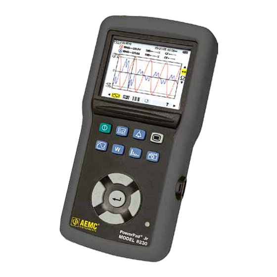
PRODUCT FEATURES 2.1 Description The PowerPad Jr. Model 8230 is a single-phase power quality analyzer that ® is easy-to-use, compact and shock-resistant. It is intended for technicians and engineers to measure and carry out diagnostic work and power quality work on single- or three-phase balanced low voltage networks. -
Page 11: Control Functions
300V CAT IV Current Probe 49.99Hz 02/25/06 10:26 RMS= 229.4V THD= 1.8% CF=1.37 RMS= 7.0 V THD= 0.00% CF=1.95 300V -300 <t= 5.0ms V1= +276 V2= -140 V3= -145 > ® PowerPad MODEL 8230 Figure 2-1 Power Quality Analyzer Model 8230... - Page 12 Moves one character of field to the left in a menu, moves the graphic cursor, makes a selection or adjusts a cursor. Infrared optical interface for USB cable Charging light Power Quality Analyzer Model 8230...
-
Page 13: Display
Simultaneous display of the various measurements in alphanumeric form Phase order Online help Selection tools: Use ▲ and ▼ to select a tool. - Selection of the sub-menu - Instantaneous measurement cursor management tool on a point of the curve Power Quality Analyzer Model 8230... -
Page 14: Power Supply
2.5 Optical Interface The optical interface (Figure 2-1, item 8) provides an optical, and therefore iso- lated, two-way connection between the 8230 and a PC for transmission of the information in memory (alarms, snapshots, motor starts, records) and all instanta- neous measurements and waveforms displayed on the screen of the 8230. -
Page 15: Specifications
Operating Range: 0 to 1V Input Impedance: 1MΩ for current probe circuit and 12.4kΩ for AmpFlex circuit ® Overload: 1.7V Sample Rate: 256 per cycle 6.4kHz (256 x 50 ÷ 2) at 50Hz; 7.68kHz (256 x 60 ÷ 2) at 60Hz Power Quality Analyzer Model 8230... -
Page 16: Accuracy Specifications (Excluding Current Probes)
9999kVAR 4 digits ® ±(2.5%+20cts) & MiniFlex ® 0.2 ≤ Sin φ < 0.5 Apparent power 9999kVA 4 digits ±(1%) ±(1.5%) Cos φ ≥ 0.5 Power factor 0.001 ±(1.5%+10cts) 0.2 ≤ Cos φ < 0.5 Power Quality Analyzer Model 8230... - Page 17 (balanced three-phase network having a phase-neutral voltage of 380 NOTE: Accuracy given for power and energy measurements are maximum for Cos φ = 1 or Sin φ = 1 and are typical for the other phase shifts. Power Quality Analyzer Model 8230...
-
Page 18: Accuracy Specifications Of The Current Probes
[100mA; 300mA] N.S. ±(0.7%+2mA) MN193 [300mA; 1A] ±(1.5°) 100A [1A; 120A] ±(0.7%) ±(0.7°) [5mA; 50mA] ±(1%+0.1mA) ±(1.7°) MN193 [50mA; 500mA] ±(1%) ±(1°) [500mA; 6A] ±(0.7%) [5mA; 50mA] ±(1%) ±(1°) Adapter [50mA; 6A] ±(0.5%) ±(0°) *DC Only Power Quality Analyzer Model 8230... -
Page 19: Current Probes And Sensors
NOTE: Currents < (Primary x 5) ÷ (Secondary x 1000) or <250mA on the 5A range and <0.2A on the 100A range will be displayed as zero with this probe. Power calculations will also be zeroed when the current is zeroed when the current is zeroed. Power Quality Analyzer Model 8230... -
Page 20: Power Supply
At least 300 charging/discharging cycles NOTE: The battery starts to charge when the power cord is connected. When the battery is charged, the instrument uses the current supplied by the power supply, without drawing from the battery. Power Quality Analyzer Model 8230... -
Page 21: Mechanical Specifications
Immunity: EN 61236-1 A2 Emission: EN 61236-1 A2 Electrostatic discharges: IEC 1000-4-2 Radiation field resistance: IEC 1000-4-3 Fast transients resistance: IEC 1000-4-4 Electric shock resistance: IEC 1000-4-5 Conducted RF interference: IEC 1000-4-6 Interruption of Voltage: IEC 1000-4-11 Power Quality Analyzer Model 8230... -
Page 22: Operation
Set the display language by using the ◄ and ► buttons. • The parameter that is ready to be configured will be highlighted in yellow. To move to a different parameter, use the ▲ and ▼ buttons. Power Quality Analyzer Model 8230... - Page 23 Defines the parameters of an alarm (see § 4.1.3) Clear Memory Deletes all data (configurations, alarm settings, snapshots and recordings). The configuration will return to the default setting. About Displays the serial number, software and hardware version. Power Quality Analyzer Model 8230...
-
Page 24: Configuring A Current Probe
▲▼ buttons to select the values. Validate the selections by pressing the Enter button. 4.1.2 Configuring a Recording Press the configuration button and select RECORDING. 07/25/02 10:26 100% 02/25/06 10:26 RECORDING Set-up CONFIG 1 VPST Figure 4-3 Power Quality Analyzer Model 8230... - Page 25 If in the Record Mode, and the display does not come ON, do not turn the instru- ment OFF. Supply power to the PowerPad Jr. with the line cord and the display ® will come back ON when any button (other than ON/OFF) is pressed. Power Quality Analyzer Model 8230...
-
Page 26: Configuring The Alarm Settings
Minimum duration from beginning threshold detection to store the alarm (from 0.01 seconds to 99 minutes) Less than “<” or greater than “>” NOTE: When the alarm is “OFF”, the parameters previously used are stored in memory and reappear if the alarm is selected again. Power Quality Analyzer Model 8230... -
Page 27: Display Modes
(except power, energy and harmonics). 49.99Hz 02/25/06 10:26 RMS= 229.4V THD= 1.8% CF=1.37 RMS= 7.0 V THD= 0.00% CF=1.95 360V -350 > <t= 5.9ms V= +314 I= +13 Figure 5-1 Power Quality Analyzer Model 8230... -
Page 28: Power Quality Analyzer Model
Minimum current displayed (A) Minimum scale value in current (A) AmpFlex Sensors ® MR193 SR193 MN93 MN193A 100A MN193A 5A (Primary x 5) / (Secondary x 1000) (Primary x 5 x 10 ) / (Secondary x 1000) Power Quality Analyzer Model 8230... -
Page 29: Power Quality Analyzer Model 8230
NOTE: The MAX and MIN measurements are calculated every half period (e.g. ev- ery 10ms for a 50Hz signal). The AVG measurements are calculated every second. However, the MAX, AVG and MIN measurements are refreshed every 250ms. Power Quality Analyzer Model 8230... -
Page 30: Simultaneous Display
Distortion factor (also called THD-R). NOTE: DC current will be displayed, however the values are only valid when a current probe capable of measuring DC is used. The MR193 probe is available for this purpose. Power Quality Analyzer Model 8230... -
Page 31: Phase Rotation
02/25/06 10:26 PHASE ORDER Step Plug Phase 1 into COM Input Plug Phase 2 into + Input to continue) Figure 5-4 • Press the Enter button. The screen will indicate that the measurement is in progress. Power Quality Analyzer Model 8230... - Page 32 Reverse sequence: The phase assumed to be L3 leads the phase assumed to be L2, which itself leads the phase assumed to be L1. 02/25/06 10:26 PHASE ORDER RESULT INDIRECT Phase Order to continue) Figure 5-6 Power Quality Analyzer Model 8230...
-
Page 33: Error Messages
DIRECT Phase Order to continue) Figure 5-7 Error Messages If the measurement is not possible, a warning message is displayed. • Waiting time exceeded • Frequency out of Range (40-70Hz) and Signal too Small (Vrms<10V) Power Quality Analyzer Model 8230... -
Page 34: Power / Energy Mode
Apparent energy consumed Power factor (ratio of active power to apparent power) Displacement factor (cosine of φ ) DPF: Tangent of angle φ Tan: Phase shift of the phase-to-earth voltage with respect to the phase-to-earth current. Power Quality Analyzer Model 8230... - Page 35 The energies and powers displayed are then the total energies and powers of the balanced three-phase network. The other measurements are unchanged. Four Quadrant Power Diagram: +VAR Reactive Power - from supply Reactive Power - from load -VAR Produced Consumed Figure 5-9 Power Quality Analyzer Model 8230...
-
Page 36: Harmonics Mode
Use ▲ and ▼ to select a tool. - Selection of the sub-menu - Zoom-Out tool. Each press on the Enter button increases the vertical scale. - Zoom-In tool. Each press on the Enter button decreases the vertical scale. Power Quality Analyzer Model 8230... -
Page 37: Current (A)
Order (1 to 25): order of the harmonics. As soon as the cursor goes past order 25, the range from 26 to 50 appears. Note: The ► icon to the right of harmonic 25 indicates the presence of harmonics of order higher than 25. Analysis of the current harmonics. Power Quality Analyzer Model 8230... -
Page 38: Apparent Power (Va)
26 to 50 appears. Note: The ► icon to the right of harmonic 25 indicates the presence of harmonics of order higher than 25. Analysis of the apparent power harmonics* *Not available with a balanced three-phase connection. Power Quality Analyzer Model 8230... -
Page 39: Voltage Expert Mode
Higher current draw for a given load. • Premature ageing of rotating machine. "Zero" sequence • Overheating of rotating machine. • Higher current draw for a given load. • Overload of the neutral. • Premature ageing of rotating machine. Power Quality Analyzer Model 8230... -
Page 40: Current Expert Mode
Higher current draw for a given load. • Premature ageing of rotating machine. "Zero" sequence • Overheating of rotating machine. • Higher current draw for a given load. • Overload of the neutral. • Premature ageing of rotating machine. Power Quality Analyzer Model 8230... -
Page 41: Snapshot Mode
Available memory indicator. The black area of the status bar indicates amount of memory used. List of saved snapshots: Each icon indicates the type of screen stored (recording, alarm, waveforms, etc.) and the date and time of the snapshot. Opens a saved snapshot. Deletes a saved snapshot. Power Quality Analyzer Model 8230... -
Page 42: Taking A Snapshot Of A Display
After reviewing the snapshot, press the Enter button again to return to the list of saved snapshots. To delete a saved snapshot: • Select the function using the ◄ and ► buttons., then press the Enter button. • Select the snapshot to be deleted. • Press the Enter button to delete. Power Quality Analyzer Model 8230... -
Page 43: Alarm Mode
Available memory indicator. The black stripe represents the memory already in use, the white stripe the memory still available. Starting and ending times of an alarm. Displays the alarms log. Programs the recording of detected alarms. Erases the alarms log. Power Quality Analyzer Model 8230... -
Page 44: Programming And Starting Alarms
Hand tool by pressing the ▼ button and then the Enter button. 5.5.2 Displaying the Alarms Log 02/25/06 10:26 OPEN ALARM LOG (1/2) 02/25/06 11:27 Vthd 23.1% Vrms 1s24 11:28 Vthd 34.3% Vthd 35.0% Arms Arms 11:29 Arms Arms Arms Vrms 109V 3s37 Figure 5-17 Power Quality Analyzer Model 8230... -
Page 45: Deleting The Alarms Log
To erase the entire alarms log: Select the icon using the ◄► buttons. Select Yes using the ▲▼ buttons, then press the Enter button. This will delete all logs. To exit without deleting, press No and then the Enter button. Power Quality Analyzer Model 8230... -
Page 46: Recording Mode
Representing the time already elapsed (black zone) with respect to the total time (white zone) of the recording in progress Sets the configuration for a new recording (see § 5.6.1) Displays a recording. Configures and starts a recording. Deletes a recording. Inrush mode (see § 5.7) Power Quality Analyzer Model 8230... -
Page 47: Starting A Recording
The bottom of the screen then indicates “Recording in progress”. NOTE: To stop the recording before the stop time occurs (with no possibility of Hand tool by pressing the ▼ button and then the resumption), select the Enter button. Power Quality Analyzer Model 8230... -
Page 48: Selecting A Recording
◄► buttons. The erase recording screen will display. • Select the recording to be deleted, then press the Enter button. NOTE: The deletion of the record may take a few seconds to complete. Power Quality Analyzer Model 8230... -
Page 49: Examples Of Recordings
Time cursor - moves by using the ◄ or ► button when the tool is selected. Returns to the previous screen. Type of measurement displayed. NOTE: The Current measurement display reveals the same information as above except in Current instead of Voltage. Power Quality Analyzer Model 8230... - Page 50 A long press on the ◄ or ► button causes a shift to rapid motion if the tool is selected. ENERGY IN SPECIFIED DURATION (Wh) 02/25/06 10:26 02/25/06 15:25:00 02/25/06 15:28:00 +4.4 Wh +1.0k +0.78k +0.56k 3> 0 Figure 5-21 Power Quality Analyzer Model 8230...
- Page 51 15 minutes over 15 hours 10 minutes over 10 hours 5 minutes over 5 hours 1 minute over 1 hour 20 seconds over 20 minutes 5 seconds over 5 minutes 1 second over 1 minute Power Quality Analyzer Model 8230...
-
Page 52: Inrush Mode (Starting Current)
Starting an Inrush Recording Select the Inrush icon from the recording display using the ► button. Select the New Inrush line and press Enter. 02/25/06 10:26 INRUSH MODE Open last Inrush New Inrush Figure 5-22 Power Quality Analyzer Model 8230... - Page 53 Recording will stop when the stopping threshold is reached. NOTE: To stop the recording at any time, select the Hand tool ( ) by pressing the ▼ button and then the Enter button. Power Quality Analyzer Model 8230...
-
Page 54: Viewing The Inrush Recording
Press Enter one more time and the waveform of the recording is displayed. If the stopping threshold is not detected, the message “Stopping threshold not detected” will be displayed. NOTE: Use the Zoom tools at any time to zoom in or out of part of the waveform. Power Quality Analyzer Model 8230... -
Page 55: Dataview ® Software
Windows is a registered trademark of Microsoft Corporation in the United States and other countries. NOTE: When installing, the user must have Administrative access rights during the installation. The users access rights can be changed after the installation is complete. DataView must be reinstalled for each user in a multi-user system. ® USB Flash Drive Install 1. Insert the USB stick into an available USB port (wait for driver to be installed). 2. If Autorun is enabled then an AutoPlay window should appear as shown. Power Quality Analyzer Model 8230... - Page 56 PDF documents supplied with DataView that are ® accessible from the Help menu. • *DataView Updates - Links to the online AEMC software updates to ® check for new software version releases. *Firmware Upgrades - Links to the online AEMC •...
- Page 57 In the Ready to Install the Program window, click on Install. 10. If the instrument selected for installation requires the use of a USB port, a warning box will appear, similar to Figure 6-3. Click OK. Figure 6-3 Power Quality Analyzer Model 8230...
-
Page 58: Connecting The Model 8230 To Your Computer
6.2 Connecting the Model 8230 to your Computer The Model 8230 is supplied with an optically isolated USB interface cable re- quired for connecting the instrument to the computer. This cable (Cat. #2135.41) is equipped with a USB type A on one end, and an optical connector on the other end. -
Page 59: Opening The Control Panel
Once the proper communication param- eters have been specified, click OK. NOTE: The communication rate is determined automatically by DataView ® the 8230 (maximum rate is 115.2 kbps). When a communication link is established, DataView will automatically identify ®... - Page 60 Window menu. NOTE: If the battery charge is shown to be unknown, plug the PowerPad Jr. into ® AC Power, when it reaches 100% charge, the display should again be able to show the battery charge. Power Quality Analyzer Model 8230...
-
Page 61: General Functions
Help: Opens the online Help. 6.3.2 Set-up Configuration The Configure the instrument dialog box (Fig. 6-6) lets you configure every aspect of the Model 8230 PowerPad Jr. Each field is identical to the programmable fea- ® tures available from the instrument’s front panel itself. -
Page 62: Instrument Display Configuration
Figure 6-7 NOTE: For detailed instructions and descriptions for any feature in a dialog box, click on the Help Button (lower right-side of the dialog box), or right-click on the feature you want information about. Power Quality Analyzer Model 8230... -
Page 63: Alarm Conditions Configuration
• Vthd: voltage total harmonic distortion • Arms: current root mean squared • Athd: current total harmonic distortion • VPST: voltage short term flicker • W: active power • Vcf: voltage crest factor • Acf: current crest factor Power Quality Analyzer Model 8230... -
Page 64: Recordings Configuration
Four different configurations are available. More configurations can be saved by pressing “Save to File” and recalled later by pressing “Load From File”. Check the configuration you wish to set up: 1, 2, 3 or 4. Power Quality Analyzer Model 8230... - Page 65 9:10. If OK or Apply is pressed, the following screen appears: Figure 6-10 Select Yes to schedule a recording, select No to bring you back to the Configure dialog box without starting a recording. Power Quality Analyzer Model 8230...
-
Page 66: Inrush Configuration
Write Changes and Start New Inrush Search: Initiates searching for an Inrush when the OK or Apply button is pressed. Power Quality Analyzer Model 8230... -
Page 67: Monitoring
The frequency is not asked for, since it will be asked for when the test result is downloaded. Follow the instructions in the dialog box to set up and run this special test. Press the Help button for further instructions. Power Quality Analyzer Model 8230... -
Page 68: Running The Test
NOT the recording screen. 6.4 Real-time Windows Once setup is complete, different views of real time data and waveforms can be viewed on-screen. 6.4.1 Waveform, Harmonic Bar and Harmonic Text Figure 6-13a Figure 6-13b Power Quality Analyzer Model 8230... -
Page 69: Power/Energy
The Power/Energy window displays accumulated power and energy data. Accumulated energy data can be started or stopped and the results can be down- loaded to a database and viewed on the screen, selected by phase. Power Quality Analyzer Model 8230... -
Page 70: Trend
“Save”. Alternatively, select “View”. After the download is complete, a window will appear with a graph of the data, and some viewing or channel options. In that window, you can select “Save”, or “Print”. Power Quality Analyzer Model 8230... -
Page 71: Recordings
Following are examples of each tab listed in the display window. 6.5.1 Recordings Figure 6-16a The Recording window displays a list of recordings within the PowerPad ® These recordings can be selected and printed or saved to a database. Figure 6-16b Power Quality Analyzer Model 8230... -
Page 72: Photographs
When “View” is selected, it shows the waveforms, power data and a Bitmap image of the PowerPad Jr. screen from the time the camera button was pressed. ® NOTE: Snapshots can only be initiated using the camera button on the PowerPad Jr. itself, not by DataView ® ® Power Quality Analyzer Model 8230... -
Page 73: Alarms
Figure 6-19a The Inrush window displays an inrush recording stored on the PowerPad Jr. It ® shows the time it began, its duration, the maximum ARMS and maximum A-Peak. The selected inrush can then be downloaded. Power Quality Analyzer Model 8230... - Page 74 These controls are available in every graph from recorded data. There is also a checkbox, “View As List”, which can be used to show the value of every datapoint. Figure 6-19c Power Quality Analyzer Model 8230...
-
Page 75: Monitoring
The ARMS display shows the ARMS of each half cycle during the inrush. Figure 6-19d 6.5.5 Monitoring The Monitoring window displays recorded tests that can be downloaded and ana- lyzed. Figure 6-20a Power Quality Analyzer Model 8230... -
Page 76: Saving Real-Time Measurements
File name field, select the desired location to save the file, then click Save to save the file. When the “Rec to PC” option is unchecked the file can be opened by selecting Yes from the View Saved File dialog box. Power Quality Analyzer Model 8230... - Page 77 In addition to the pre-designed report templates, DataView allows you to totally ® configure reports to your needs. Refer to the DataView HELP file on “Tem- ® plates” to learn more about templates. Power Quality Analyzer Model 8230...
-
Page 78: Maintenance
1) having a capacity of at least 1800 mAh. The storage batteries are recharged using the external power unit supplied with the instrument. It is connected to the 8230 using the jack. Use only the external power unit supplied with the equipment. -
Page 79: Changing The Battery
• Do not expose the battery to heat exceeding 212°F (100°C). • Do not short-circuit the battery terminals. To access the batteries, turn the 8230 over and turn the lock one-quarter turn (Figure 7-1, item 2) counter-clockwise using a coin (Figure 7-1, item 3). -
Page 80: Appendix A: Mathematical Formulas
NSHC Zero NSHC: number of samples per half cycle (between two consecutive zeros) n: sample (0; 255) MIN / MAX Values for Voltage and Current Vmax= max (Vhalf), Vmin=min (Vhalf) Amax= max (Ahalf), Amin=min (Ahalf) Power Quality Analyzer Model 8230... -
Page 81: Short-Term Flicker (Pst) Of The Voltage
(Vpp − Peak factor voltage ∑ ⋅ max (App − ∑ Peak factor current ⋅ 1 sec RMS Values for Voltage and Current − Vrms ∑ Rms voltage ⋅ − Arms Rms current ∑ ⋅ Power Quality Analyzer Model 8230... -
Page 82: Harmonic Calculations
RM S RM S ² − ² Total Reactive power NSS-1 if computation method ∑ is without harmonics × U = voltage phase to phase between phase 1 to phase 2 A = phase 3 Power Quality Analyzer Model 8230... -
Page 83: K Factor
Inductive reactive energy generated 3600 Tint − ∑ ≥ for VAR < 0 and W VARhCc Capacitive reactive energy consumed 3600 Tint ∑ ≥ VARhCg for VAR 0 and W < 0 Capacitive reactive energy generated 3600 Tint Power Quality Analyzer Model 8230... -
Page 84: Hysteresis
2% Uref Level to go back = 100% - 2% = 98% Uref Swell duration Undervoltage or blackout detection Duration Level to go back = (100% + 2%)Uref Hysteresis = 2% Uref Threshold = 102% Uref Power Quality Analyzer Model 8230... -
Page 85: Appendix B: Glossary Of Units
Level of order ‘x’ harmonic in voltage (phase-to-phase 3 φ Vrms True RMS voltage (phase-to-phase 3 φ Vthd Total harmonic distortion of the voltage (phase-to-phase 3 φ Active power (total 3 φ Active energy (consumed of generated; total 3 Power Quality Analyzer Model 8230... -
Page 86: Repair And Calibration
Chauvin Arnoux , Inc. d.b.a. AEMC Instruments ® ® 200 Foxborough Boulevard Foxborough, MA 02035 USA Phone: (800) 343-1391 (508) 698-2115 Fax: (508) 698-2118 E-mail: techsupport@aemc.com www.aemc.com NOTE: Do not ship Instruments to our Foxborough, MA address. Power Quality Analyzer Model 8230... -
Page 87: Limited Warranty
Limited Warranty The PowerPad Jr. Model 8230 is warranted to the owner for a period of one ® year from the date of original purchase against defects in manufacture. This limited warranty is given by AEMC Instruments, not by the distributor from ®... - Page 88 05/13 99-MAN 100296 v14 Chauvin Arnoux , Inc. d.b.a. AEMC Instruments ® ® 15 Faraday Drive • Dover, NH 03820 USA • Phone: (603) 749-6434 • Fax: (603) 742-2346 www.aemc.com...
Need help?
Do you have a question about the 8230 and is the answer not in the manual?
Questions and answers