Table of Contents
Advertisement
Quick Links
Advertisement
Table of Contents

Related Manuals for AEMC 8220


Summary of Contents for AEMC 8220
- Page 1 8220 SINGLE-PHASE POWER QUALITY ANALYZER E N G L I S H User Manual...
- Page 2 For recalibration, please use our calibration services. Refer to our repair and calibration section at www.aemc.com. Serial #: ____________________________________ Catalog #: __________________________________ Model #: 8220 & 8220 Kits Please fill in the appropriate date as indicated: Date Received: _________________________________ _______________________ Date Calibration Due: Chauvin Arnoux , Inc.
-
Page 3: Table Of Contents
Print Button ..............16 2.6.5 Arrow Buttons ...............16 2.6.6 White Button .................17 2.6.7 Yellow Button ................17 3. SPECIFICATIONS ................18 3.1 Reference Conditions.................18 3.2 Electrical Specifications ..............18 3.2.1 Voltage Inputs ...............18 3.2.2 Current Inputs ...............19 3.2.3 Bandwidth ................19 3.2.4 Power Supply ................20 3.2.5 Accuracy Specifications (excluding current probes) ...21 Power Quality Analyzer Model 8220... - Page 4 5.1 Installing DataView ................47 ® 5.2 Connecting the Model 8220 to your Computer ........50 5.3 Opening the Control Panel ..............51 5.3.1 Common Functions ...............52 5.3.2 Instrument Configuration............52 5.3.3 Inrush and RPM Configuration..........54 Real-time Windows ................55 5.4.1 Waveform, Harmonic Bar and Harmonic Text .......55 5.4.2 Power/Energy ...............56 5.4.3 Trend ..................57 5.5 Downloading Data to Database ............57 5.6 Saving Real-time Measurements ............58 Power Quality Analyzer Model 8220...
- Page 5 Different Power Levels 1 Sec in Single-Phase Connection ......64 Different Power Levels 1 Sec in Balanced Three-Phase Connection ..64 Ratios ......................65 K Factor .......................65 Various Types of Energy ................65 Hysteresis ....................66 Diagram of 4 Quadrants ................67 Saturation of Input Channels ...............67 Repair and Calibration ............... 68 Technical and Sales Assistance ............68 Limited Warranty ................69 Warranty Repairs ................69 Power Quality Analyzer Model 8220...
-
Page 6: Introduction
EMC. The trash can with a line through it means that in the European Union, the product must undergo selective disposal for the recycling of electric and electronic material, in compliance with Directive WEEE 2002/96/EC. Power Quality Analyzer Model 8220... -
Page 7: Definition Of Measurement Categories
® Model 8220 w/MN93-BK ..............Cat. #2130.91 Includes the Model 8220, one MN93 (240A) current probe (black connector), set of two 10 ft (3m) color-coded leads (red/black) with alligator clips, set of safety test probes (red/black), optically iso- lated USB cable, set of six 1.5V AA batteries, DataView software, carrying bag, and user manual. -
Page 8: Accessories And Replacement Parts
Model 8220 w/MN193-BK ...............Cat. #2130.96 Includes the Model 8220, one MN193 (6A/120A) current probe (black connector), set of two 10 ft (3m) color-coded leads (red/black) with alligator clips, set of safety test probes (red/black), optically isolated USB cable, set of six 1.5V AA batteries, carrying bag, and USB stick supplied with product user manual and DataView software. -
Page 9: Product Features
Within seconds you will be gathering the measurements you want. The Model 8220’s accuracy is better than 1% (excluding current sensors). It has a great flexibility due to AEMC’s range of current sensors, measuring from a few hundred milliamps to several thousand amps. The Model 8220 is designed for technicians, control and maintenance engineers, as well as electrical contractors, inspectors and educators. NOTE: The Model 8220 can be powered by 6 x AA batteries or a 110V/220V power adaptor (with batteries removed). Features: • Measures up to 660Vrms or V • Measures up to 6500A... -
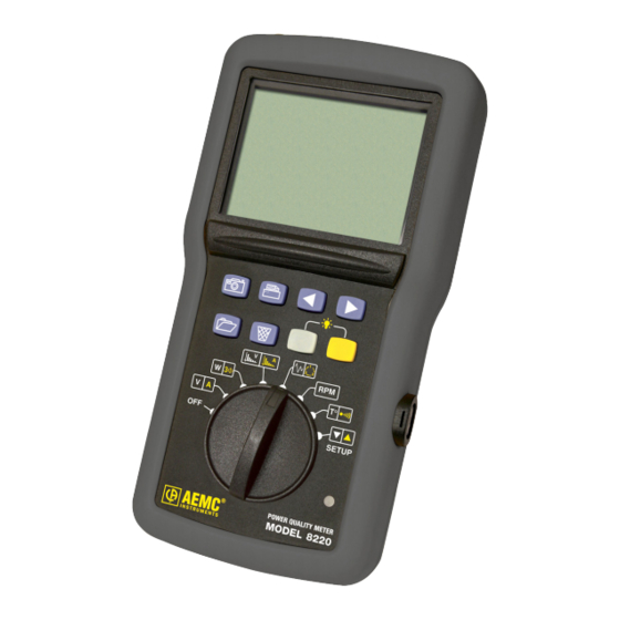
Page 10: Control Features
® • Download stored data to DataView software via optical USB port ® • Includes FREE DataView software for data storage, real-time wave- ® form display, analysis and report generation 2.2 Control Features Voltage Use Factory Inputs Power Supply 600V CAT III Use Factory 300V CAT IV Current Probe Figure 2-1 Power Quality Analyzer Model 8220... - Page 11 Yellow Button Accesses the current, balanced three-phase, current harmonic, phase rotation and resistance modes, reduces the value in the configuration mode. Also inhibits automatic extinction. NOTE: For detailed information on these buttons, see § 2.6 Power Quality Analyzer Model 8220...
- Page 12 NOTE: For detailed information on these modes, see § 4.6. Infrared optically coupled interface for USB cable. Light indicator: ON - indicates the 8220 is running on the optional external power supply. OFF - indicates the 8220 is running on the internal batteries. Power Quality Analyzer Model 8220...
-
Page 13: Display
Voltage or current harmonics measurement Motor starting (inrush) measurement Phase rotation Rotation speed measurement Temperature measurement Resistance measurement (up to 2000Ω) When displayed, indicates the battery is low Flashes during data transfer of information to the external printer Power Quality Analyzer Model 8220... - Page 14 Rotation speed in revolutions per minute (rotation per minute) Duration in seconds THD-F Total Harmonic Distortion (or THD) THD-R Distortion Factor (or DF) Voltage in volts Apparent Power (total if 3Φ) Reactive Power (total if 3Φ) Active Power (total if 3Φ) Power Quality Analyzer Model 8220...
-
Page 15: Power Supply
The transfer rate is determined automatically by the Model 8220 according to the software used; the maximum rate is 115.2 kbps. 2.6 Button Functions 2.6.1 Photograph Button This button photographs all the measurement pages displayed in the following rotary switch positions: When the button is pressed, all the pages in the voltage, current, power, voltage harmonics and current harmonics modes are photographed and the next screen is displayed. Power Quality Analyzer Model 8220... -
Page 16: View Button
NOTE: If the memory used for storing the photographs is full, the message (Memory full) message is displayed. 2.6.2 View Button This button first gives access to the list of photographs, then enables the user to select a photograph to be viewed. To Display a List of Photographs: Press the button. A number of a photograph in the list will be displayed. Use the ◄► buttons to: • Display the number of a specific photograph to be viewed (see illustration above). • Select to select all photographs. This list can be exited by pressing either the White or Yellow button ( ) or the button, or by changing the position of the switch. If the Model 8220 memory does not contain any photographs, is displayed on the screen. The instrument then automatically returns to the preview mode. Power Quality Analyzer Model 8220... -
Page 17: Delete Button
Delete Button This button is used to delete one or all of the previously saved photographs. To Delete a Photograph: Press the button to view the list of photographs. Use the ◄► buttons to: • Display the number of a specific photograph to be deleted (see illustration on previous page). • Select to select all photographs. Press the button to delete the selected photograph. WARNING: Selecting will delete all saved photographs. After deleting a specific photograph, one of the numbers of the remaining photo- graphs is displayed. If the list does not contain any further photos, the display indicates (no recording). The display then switches automatically to a measurement mode. This list can be exited by pressing either the White or Yellow button ( ) or the button, or by changing the position of the switch. was selected, is displayed on the screen. The display then auto- matically switches to a measurement mode. Power Quality Analyzer Model 8220... -
Page 18: Print Button
************************** Mode:voltage Vrms(V)= 225.7 Arms(A)= 112.8 Freq(Hz)= 50.00 Vdc(V)= 3.2 CF= 1.41 Vmax(V)= 229.4 Vmin(V)= 222.6 Vpeak+(V)= 319.6 Vpeak-(V)=-313.3 Figure 2-4 ◄► Buttons 2.6.5 These buttons enable the user to: • Navigate between pages for the modes. • Activate or de-activate the balanced three-phase mode for the mode. • Select the step in the modes. Power Quality Analyzer Model 8220... -
Page 19: White Button
, ). • Decreasing the values in the mode. • Exiting the list of photographs. • Display of the information relating to the 8220 (serial, software and hardware numbers). This information is accessed by pressing and holding down the white button when turning the rotary switch from OFF to any other position. 2.6.7 Yellow Button This button enables: • Selection of the second function of each mode, indicated by the yellow mark- ings around the rotary switch ( • Increasing the values in the mode. • Exiting the list of photographs. • De-activation of the automatic shut-off (see § 4.4). Power Quality Analyzer Model 8220... -
Page 20: Specifications
*All specifications are subject to change without notice. 3.2 Electrical Specifications 3.2.1 Voltage Inputs Switch Positions: Operating Range: Phase-Phase - 0 to 660Vrms AC/DC* Phase-Neutral - 0 to 600Vrms AC/DC *Provided that the max with 600Vrms in regards to earth is not exceeded. Input Impedance: 451kΩ Overload: 1.2Vn permanently; 2Vn for 1 sec (Vn = nominal voltage) Power Quality Analyzer Model 8220... -
Page 21: Current Inputs
Measurement Current: 500µA Overload: 600Vrms continuous Threshold for Buzzer: 20Ω (by default) 3.2.2 Current Inputs Operating Range: 0 to 1V Input Impedance: 1MΩ for current probe circuit and 12.4kΩ for AmpFlex circuit ® Overload: 1.7V 3.2.3 Bandwidth Measurement Channels: 256 points per period, or: • For 50Hz: 6.4kHz (256 × 50 ÷ 2) • For 60Hz: 7.68kHz (256 × 60 ÷ 2) Analog to -3dB: > to 10kHz Power Quality Analyzer Model 8220... -
Page 22: Power Supply
Standard batteries: -4° to 158°F (-20°C to 70°C) Rechargeable batteries: -4° to 122°F (-20°C to 50°C) NOTE: Rechargeable batteries must be recharged on an external charger. AC Power (external power supply) Operating Range: 120V ± 10% @ 60Hz ; 230V ± 10% @ 50Hz (model dependent) Max Power: 23.7VA The instrument may be powered by an optional Power Adapter 110V (Cat. #2140.37) or 220V (Cat. #2140.38) Power Quality Analyzer Model 8220... -
Page 23: Accuracy Specifications (Excluding Current Probes)
0.2 ≤ Sin φ < 0.5 Apparent power 9999kVA 4 digits ±(1%) ±(1.5%) Cos φ ≥ 0.5 Power factor 0.001 ±(1.5%+10cts) 0.2 ≤ Cos φ < 0.5 *NOTE: MiniFlex specified up to 1000A only ® Power Quality Analyzer Model 8220... - Page 24 ± (1 %+8°F). NOTE: The uncertainties given for power and energy measurements are maximum for Cos φ = 1 or Sin φ = 1 and are typical for the other phase shifts. Power Quality Analyzer Model 8220...
-
Page 25: Accuracy Specifications Of The Current Probes
±(1%) ±(1°) Adapter [50mA; 6A] ±(0.5%) ±(0°) [0 A ; 40 A] ±(2% + 50mA) ±(0.5°) SL261 10mV/A [40 A; 100 A] ±(5%) ±(0.5°) SL261 100mV/A [0 A ; 10 A] ±(1.5% + 50mA) ±(1°) Power Quality Analyzer Model 8220... -
Page 26: Current Probes And Sensors
NOTE: Currents < (Primary x 5) ÷ (Secondary x 1000) or <250mA on the 5A range and <0.2A on the 100A range will be displayed as zero with this probe. Power calculations will also be zeroed when the current is zeroed when the current is zeroed. Power Quality Analyzer Model 8220... -
Page 27: Mechanical Specifications
Maximum Clamping Diameter 0.46" (11.8mm) Safety EN 61010-2-032, Pollution Degree 2, 600V CAT III 300V CAT IV 3.3 Mechanical Specifications Dimensions: 8.3 x 4.3 x 2.4" (211 x 108 x 60mm) Weight: 1.94 lbs (880g) Shock and Vibration: per EN 61010-1 Tightness: IP 54 per EN 60529 (electrical IP2X for the terminals) Power Quality Analyzer Model 8220... -
Page 28: Environmental Specifications
Reference Temperature: 20 to 26°C (68 to 78.8°F) from 45 to 75% RH Operating Temperature: 0 to 50°C (32 to 122°F) from 10 to 85% RH Storage Temperature: With batteries: -20 to 50°C (-4 to 122°F) from 10 to 85% RH Without batteries: N/A Recharging Temperature: N/A Altitude: Operating: 0 to 2000 meters (6560 ft) Non-Operating: 0 to 10,000 meters (32800 ft) 3.5 Safety Specifications Electrical Safety 600V CAT III, Pollution Degree 2 EN 61010-31: 2002 EN 61010-1: 2001 EN 61010-2: 1995 Electromagnetic Compatibility Immunity: EN 61236-1 A2 Emission: EN 61236-1 A2 Electrostatic discharges: IEC 1000-4-2 Radiation field resistance: IEC 1000-4-3 Fast transients resistance: IEC 1000-4-4 Electric shock resistance: IEC 1000-4-5 Conducted RF interference: IEC 1000-4-6 Interruption of Voltage: IEC 1000-4-11 Power Quality Analyzer Model 8220... -
Page 29: Operation
MN93 200A Current Probe MN193 100A or 5A Current Probe SR193 1000A Current Probe AmpFlex 3000A or MiniFlex 1000A Current Sensor ® ® SL261 10A or 100A Current Probe Three-phase 5A Adapter The Model 8220 works from a battery only if the battery is sufficiently charged. The instrument can be used with the optional AC power unit connected to the power jack (see Figure 2-1, item 1). Power Quality Analyzer Model 8220... -
Page 30: Connecting The Cables
• Voltage measurement: COM and (+) terminals. • Current measurement: 4-pin connector. On the current sensor, do not forget to position the switch (if available) to a sensitivity suited to the current to be measured. The measurement cables are connected to the circuit to be monitored as per the following diagrams. 4.2.1 Single-phase Network All voltages measured will be line-to-neutral. The mode (balanced three-phase) will be de-activated ( ). See § 4.6.2. Figure 4-1 Single-phase connection 4.2.2 Balanced Three-phase Network All voltages measured will be phase-to-phase. The mode (balanced three-phase) will be activated ( ). See § 4.6.2. Figure 4-2 Balanced three-phase connection Power Quality Analyzer Model 8220... -
Page 31: Using The 5A Adapter / Mn193 5A Current Probe
4. Adjust the secondary sensor current. • Select the parameter (secondary adjustment page) with the ◄► buttons. • With the white and yellow buttons, adjust the secondary current ( ) of the transformation ratio to 1 or 5 A. See § 4.5 for details. 4.4 Automatic Shut-off By default, the automatic shut-off feature is activated each time the Model 8220 is turned on. To de-activate: 1. Turn the unit OFF by turning the rotary switch to the OFF position. 2. Turn the unit back ON by turning the rotary switch to any other position. 3. When the first screen is displayed (display of all symbols), press and hold the yellow button until a beep is heard. 4. The screen indicates (No automatic shut-off). Power Quality Analyzer Model 8220... -
Page 32: Instrument Configuration
When the motor starting current reaches or exceeds this threshold, the Model 8220 will count the time during which the effective half-cycle current value is strictly in excess of the effective half-cycle end value (see Figure 4-14). The value is set using the White and Yellow ( ) buttons. The minimum and maximum values are 0 and 5999A. Parameter Page 2: The symbol means hysteresis. This parameter is used to configure the Inrush mode. parameter sets the effective half-cycle current value serving as the end of motor start threshold. As soon as the motor starting current is over or equal to the effective half-cycle current end (stop) value, the Model 8220 will stop counting the starting time (see Figure 4-13). Power Quality Analyzer Model 8220... - Page 33 This parameter configures the primary current of the transformation ratio ( NOTE: This screen is only displayed if the Model 8220 is connected to a 5A adapter or to the MN193 5A clamp. For all of the other sensors, which do not require any adjustment, this screen is not displayed: Figure 4-4 Display of the effective primary current.
- Page 34 This parameter configures the primary current of the transformation ratio ( NOTE: This screen is only displayed if the Model 8220 is connected to a 5A adapter or to the MN193 5A clamp. For all of the other sensors, which do not require any adjustment, this screen is not displayed: Figure 4-5 Display of the effective secondary current.
- Page 35 This parameter is designed to configure the rotation speed mode ( The parameter defines the number of events per rotation for the measure- ment of rotation speed for a machine in operation. Example: If a tachometer signal provides two pulses per revolutions, this parameter would be set to 2. The value is set using the White and Yellow ( ) buttons. The minimum and maximum values are 1 and 99. Parameter Page 6: The symbol means threshold. This parameter is designed to configure the rotation speed mode ( Power Quality Analyzer Model 8220...
- Page 36 Display of the threshold voltage of the tachometer sensor. The parameter defines the threshold voltage value used to detect an event (pulse on the tachometer signal). Since the signal received by the Model 8220 can be unipolar or bipolar, two types of threshold (0.3 and 1.1V) can be selected. The recommended selection is as follows: • bipolar signals: 0.3V threshold • unipolar signals: 1.1V threshold In both cases, the hysteresis is 0.2 V. The value is set using the White and Yellow ( ) buttons. See below for the graphs for this hysteresis. Event No event 0.9 1.1 Tachometer signal (V) Event No event Tachometer signal (V) Figure 4-9 Power Quality Analyzer Model 8220...
-
Page 37: Rotary Switch Modes
Effective minimum (Hz) (VCF) voltage half-cycle – value (Vrms 1/2 max)* # of page displayed / total # of pages * The effective maximum and minimum half-cycle values may be reinitialized by pressing the Delete button. Power Quality Analyzer Model 8220... - Page 38 Current K factor (Hz) (ACF) minimum half-cycle (AKF) value (Vrms 1/2max)* # of page displayed / total # of pages * The effective maximum and minimum half-cycle values may be reinitialized by pressing the Delete button. Power Quality Analyzer Model 8220...
-
Page 39: Power And Three-Phase Calculations
# of page displayed / total # of pages *The powers displayed are the total powers (sum of 3 phases) if the symbol is displayed. **The total continuous power (WDC) is not shown if the symbol is displayed. Power Quality Analyzer Model 8220... - Page 40 Figure 4-13 Counter statuses are: • On <=> counter operative • Stop <=> counting stopped (counter values) • Off <=> counter not operative (counter values reading 0) If the instrument is not in “view a photo” mode when page 3/12 is in Power Mode, is displayed. • The button generates a switch from OFF to ON • The button either generates a switch from ON to Stop or from Stop to OFF. The causes for an automatic switch from ON to Stop: • Current sensor removed • Rotary switch on a position other than • Viewing of a photo Power Quality Analyzer Model 8220...
- Page 41 4th Page Number of hours (h) Number of minutes (n) Number of seconds (s) # of page displayed / total # of pages NOTE: Beyond 999h, 59m, 59s, “---h --m --s” is displayed, but the internal count- ing time continues to function correctly. Pages 5/12 to 12/12: Pages 5, 6, 7 and 8 concern power received by the “Load” side. Pages 9, 10, 11 and 12 concern power generated by the load side and therefore received by the “Supply” side. Figure 4-15 Power Quality Analyzer Model 8220...
- Page 42 - [1.000 k ; 9999 k] - [10.0 M ; 999 M] - [1.00 G ; 999 G] Beyond 999 999 999 999 xh (999 Gxh) “----” is displayed but the internal counters continue to function correctly. The precision of the internal counters is greater than that of the power displayed on the instrument (this is due to display limitations – number of digits available). Pages 6 and 10 out of 12 concern inductive reactive energy “L”. Pages 7 and 11 out of 12 concern capacitive reactive energy “C”. Second Function: THREE-PHASE CALCULATIONS When in view mode, the display indicates : The calculations associated with the connection of the Model 8220 to a three-phase balanced network are deactivated. This choice is selected when measuring single-phase networks. : The calculations associated with the connection of the Model 8220 to a three-phase balanced network are activated. This choice is selected when measuring three-phase balanced networks. The choice is made using the ◄ and ► buttons. Power Quality Analyzer Model 8220...
-
Page 43: Voltage And Current Harmonics
Percentage of the continu- Percentage of this (VTHD-R, also noted as VDF) ous value compared with effective value compared the effective fundamental with the effective value fundamental value # of page displayed / total # of pages Power Quality Analyzer Model 8220... - Page 44 In this value example, the fundamental is 100% of itself # of page displayed / total # of pages *With an MR current probe connected **Without an MR current probe connected Power Quality Analyzer Model 8220...
-
Page 45: Inrush And Phase Rotation
The Model 8220 automatically moves on to Step 3. Step 3: • As soon as the motor starting threshold is reached, the timer is started (Fig. 4-18, No. 2). • Once the motor to be monitored is running, the Model 8220 waits until the effective half-cycle current goes below the current set threshold (end of start threshold). The effective current calculated over one second is continuously displayed (Fig. 4-18, No. 1). The unit automatically moves on to Step 4. Figure 4-18 The timer (bottom value) is active until the low current threshold has been reached. - Page 46 ( can be ). The most important point is to respect the voltage connections as directed in 1 and 3. Step 1: • Turn the rotary switch to the position then press the Yellow button. The display will indicate that the Model 8220 is ready. • Once the test leads are connected to the suspected L1 and L2 phases, press the ► button. • The message is displayed briefly. Power Quality Analyzer Model 8220...
- Page 47 - The three-phase network frequency is outside the 40 to 70Hz range. - The voltage signal is too weak (below 10V - Operations were incorrectly carried out. To return to the first Step, press the◄ button. Step 3: • The display will then show either: - Correct order of phases: L1-L2-L3 - Incorrect order of phases: L3-L2-L1 Power Quality Analyzer Model 8220...
-
Page 48: Rotation Speed (Rpm)
4.6.5 Rotation Speed (RPM) This mode requires the Model 8220 to be pre-configured (refer to § 4.5). In this position, the Model 8220 measures the rotation speed of a turning ele- ment. NOTE: The tachometer signal should be applied into the voltage (+) and (COM) terminals of the Model 8220. The unit then measures the interval of time be- tween each signal pulse (event) and subtracts the rotation speed in revolutions per minute. -
Page 49: Dataview ® Software
NOTE: If Autorun is disabled, it will be necessary to open Windows Explorer, then locate and open the USB stick drive labeled “DataView” to view the files on the drive. 3. In the AutoPlay window, select Open Folder to view Files. 4. Double-click on Setup.exe from the opened folder view to launch the Data- View setup program. Power Quality Analyzer Model 8220... - Page 50 ® required for viewing PDF documents supplied with DataView ® *DataView Updates - Links to the online DataView • software updates to ® check for new software version releases. • *Firmware Upgrades - Links to the online firmware updates to check for new firmware version releases. • Documents - Shows a list of instrument related documents that you can view. Adobe Reader is required for viewing PDF documents supplied ® with DataView ® DataView, Version x.xx.xxxx option should be selected by default. Select the desired language and then click on Install. The Installation Wizard window will appear. Click Next. To proceed, accept the terms of the license agreement and click Next. Power Quality Analyzer Model 8220...
- Page 51 NOTE: The PDF-XChange option must be selected to be able to generate PDF reports from within DataView ® Figure 5-2 12. In the Ready to Install the Program window, click on Install. 13. If the instrument selected for installation requires the use of a USB port, a warning box will appear, similar to Figure 5-3. Click OK. Figure 5-3 Power Quality Analyzer Model 8220...
-
Page 52: Connecting The Model 8220 To Your Computer
Add/Remove Hardware utility to remove the instrument driver before repeating the process. 5.2 Connecting the Model 8220 to your Computer The Model 8220 is supplied with an optically isolated USB interface cable re- quired for connecting the instrument to the computer. This cable (Cat. #2135.41) is equipped with a USB type A on one end, and an optical connector on the other end. -
Page 53: Opening The Control Panel
Figure 5-4 Make sure that the communication port displayed in the dialog box matches the port that the serial cable is plugged into. Once the proper communication param- eters have been specified, click on OK. NOTE: The communication rate is determined automatically by DataView ® the Model 8220 (maximum rate is 115.2 kbps). When a communication link is established, DataView will automatically identify ® the instrument that it is connected to and the Control Panel will open (Fig. 5-5). Figure 5-5 Power Quality Analyzer Model 8220... -
Page 54: Common Functions
• Save to File: Saves the current configuration. This file will reside on the computer’s disk drive. Saving different configuration setups can be useful for future functions and tests. • Load from File: Retrieves a saved file from the computer’s disk drive to be used in programming the Model 8220. • OK: Closes the dialog box and brings up the Control Panel. • Cancel: Exits without saving configuration. • Apply: Programs the Model 8220 using the current settings without closing the window. • Help: Opens the online Help. 5.3.2 Instrument Configuration To configure the instrument, go to Instrument > Configure or select Configuration from the Instrument Tree. The Configure dialog box lets you configure every aspect of the Model 8220. Each field is identical to the programmable features available from the instrument’s front panel itself. Several of the functions are configured by typing the appropriate value in the field provided. Others are configured by clicking on the appropriate radio button or Icon, such as, selecting the current probe. Power Quality Analyzer Model 8220... - Page 55 Connection Type: Single-Phase or 3-Phase balanced. • Voltage Transformer Ratio: Sets the scale for voltage measurement in cases where measurements are on the secondary side of a transformer and the primary value needs to be displayed. Data is saved on the PC, but not written to the instrument. Corrected values will only be visible in DataView ® • Instrument Clock: Programs the computer’s time and date into the configuration of the Model 8220. NOTE: For detailed instructions and descriptions for any feature in a dialog box, right-click on the feature you want information about. Power Quality Analyzer Model 8220...
-
Page 56: Inrush And Rpm Configuration
2. Select the hysteresis percentage for ending the inrush capture. The inrush recording ends when the current is below the threshold minus the hysteresis percentage, or when the maximum number of datapoints have been cap- tured. RPM: The parameter defines the threshold voltage value used to detect an event (pulse on the tachometer signal). Since the signal received by the Model 8220 can be unipolar or bipolar, two types of threshold (0.3 and 1.1V) can be selected. The recommended selection is as follows: • bipolar signals: 0.3V threshold • unipolar signals: 1.1V threshold In both cases, the hysteresis is 0.2 V. The value is set using the White and Yellow ( ) buttons. Power Quality Analyzer Model 8220... -
Page 57: Real-Time Windows
5.4 Real-time Windows Once setup is complete, different views of real time data and waveforms can be viewed on-screen. 5.4.1 Waveform, Harmonic Bar and Harmonic Text Figure 5-8a Figure 5-8b Power Quality Analyzer Model 8220... -
Page 58: Power/Energy
Figure 5-8c In each Real-time window, you can: • Select the type of data to review. • Stop the update with the Hold function. • Print the selected real-time window. • Save it to disk. There is a choice of either .dvb (database to be viewed in DataView) or .csv (file to view in a spreadsheet program). 5.4.2 Power/Energy Figure 5-9 Power Quality Analyzer Model 8220... -
Page 59: Trend
NOTE: More data types are downloaded to a database or spreadsheet than what is shown on the screen. Downloading Data to Database From the Instrument menu, select “Recorded Data” to download the data • recorded in the Model 8220. - Select the data you want to Download by clicking on the desired tab (All, Photographs or Inrush), then clicking on the file name. - You can then choose to View the data or create a DataView Report or ® Spreadsheet by clicking on the appropriate button at the bottom of the dialog box. Power Quality Analyzer Model 8220... -
Page 60: Saving Real-Time Measurements
To edit the Session Properties, return to the Power Analyzer Control Panel and select File > Edit Session Properties. Figure 5-11 The Session Properties dialog box allows you to specify the Operator, Site and Custom parameters that are to be saved with recorded data. These parameters are used when generating reports. Power Quality Analyzer Model 8220... -
Page 61: Power Quality Analyzer Model 8220
In addition to the pre-designed report templates, DataView allows you to totally ® configure reports to your needs. Refer to the DataView HELP file on “Tem- ® plates” to learn more about templates. Power Quality Analyzer Model 8220... -
Page 62: Maintenance
There must be a delay of at least one minute without the battery being connected. • Do not expose the battery to heat exceeding 212°F (100°C). • Do not short-circuit the battery terminals. The Model 8220 is powered by six AA (LR6 - NEDA 15A) batteries (standard or rechargeable). To access the batteries, turn the instrument over and turn the lock one-quarter turn (Figure 6-1, item 2) counter-clockwise using a coin (Figure 6-1, item 3). Figure 6-1 Power Quality Analyzer Model 8220... -
Page 63: Recharging The Rechargeable Batteries
6.2 Recharging the Rechargeable Batteries The Model 8220 may be powered by six rechargeable NiMH batteries (available as an option) having a capacity of at least 1800 mAh. The instrument does not recharge its own rechargeable batteries. These must be charged on an external charger after removing the batteries from the unit. 6.3 Cleaning Disconnect the instrument from any source of electricity. • Use a soft cloth, lightly dampened with soapy water • Wipe with a damp cloth and then dry with a dry cloth • Do not splash water directly on the clamp • Do not use alcohol, solvents or hydrocarbons Power Quality Analyzer Model 8220... -
Page 64: Appendix A: Mathematical Formulas
(Next Zero)-1 ∑ Vhalf ⋅ Rms voltage NSHC Zero (Next Zero)-1 ∑ Ahalf ⋅ Rms current NSHC Zero n: sample (0; 255) MIN / MAX Values for Voltage and Current Vmax=max (Vhalf), Vmin=min (Vhalf) Amax=max (Ahalf), Amin=min (Ahalf) Power Quality Analyzer Model 8220... -
Page 65: Peak Voltage And Current
(Vpp − ∑ Peak factor voltage ⋅ max (App − ∑ Peak factor current ⋅ 1 sec RMS Values for Voltage and Current − Vrms ∑ Rms voltage ⋅ − Arms Rms current ∑ ⋅ Power Quality Analyzer Model 8220... -
Page 66: Harmonic Calculations
Total Active power − × Total Apparent power ⋅ ⋅ RM S RM S ² − ² Total Reactive power NSS-1 if computation method ∑ is without harmonics × U = voltage phase to phase between phase 1 to phase 2 A = phase 3 Power Quality Analyzer Model 8220... -
Page 67: Ratios
Inductive reactive energy generated 3600 Tint − ∑ ≥ for VAR < 0 and W VARhCc Capacitive reactive energy consumed 3600 Tint ∑ ≥ VARhCg for VAR 0 and W < 0 Capacitive reactive energy generated 3600 Tint Power Quality Analyzer Model 8220... -
Page 68: Hysteresis
2% Uref Level to go back = 100% - 2% = 98% Uref Swell duration Undervoltage or blackout detection Duration Level to go back = (100% + 2%)Uref Hysteresis = 2% Uref Threshold = 102% Uref Power Quality Analyzer Model 8220... -
Page 69: Diagram Of 4 Quadrants
No monitoring of the saturation of input channels is carried out when the instru- ment is in information display mode or in the following modes: Saturation indicator for voltage input channel Saturation indicator for current input channel NOTE: It is normal for the above screen to be displayed when the current sensor is installed or removed. Power Quality Analyzer Model 8220... -
Page 70: Repair And Calibration
NOTE: You must obtain a CSA# before returning any instrument. Technical and Sales Assistance If you are experiencing any technical problems, or require any assistance with the proper operation or application of your instrument, please call, mail, fax or e-mail our technical support team: Chauvin Arnoux , Inc. d.b.a. AEMC Instruments ® ® 200 Foxborough Boulevard Foxborough, MA 02035 USA Phone: (800) 343-1391 (508) 698-2115 Fax: (508) 698-2118 E-mail: techsupport@aemc.com www.aemc.com NOTE: Do not ship Instruments to our Foxborough, MA address. Power Quality Analyzer Model 8220... -
Page 71: Limited Warranty
Instruments, not by the distributor from whom it ® was pur-chased. This warranty is void if the unit has been tampered with, abused or if the defect is related to service not performed by AEMC ® Instruments. Full warranty coverage and product registration is available on our website at www.aemc.com/warranty.html. - Page 72 03/17 99-MAN 100297 v19 Chauvin Arnoux , Inc. d.b.a. AEMC Instruments ® ® 15 Faraday Drive • Dover, NH 03820 USA • Phone: (603) 749-6434 • Fax: (603) 742-2346 www.aemc.com...
Need help?
Do you have a question about the 8220 and is the answer not in the manual?
Questions and answers