
Related Manuals for AEMC 8500


Summary of Contents for AEMC 8500
- Page 1 8500 DIGITAL TRANSFORMER RATIOMETER MEDIDOR DE RAZÓN DE TRANSFORMADOR DIGITAL E N G L I S H User Manual E S PA Ñ O L Manual de Instrucciones...
- Page 2 Refer to our repair and calibration section at www.aemc.com. Serial #: ________________________________ Catalog #: 2111.80 / 2116.21 Model #: 8500 (115V) / 8500 (230V) Please fill in the appropriate date as indicated: Date Received: _________________________________ _______________________ Date Calibration Due: Chauvin Arnoux , Inc.
-
Page 3: Table Of Contents
CT Test Mode Flow Chart ...........15 4.5 Displayed Messages ...............16 4.6 Power Supply ................17 4.7 Changing Power Supply Setting from 115V to 230V or 230V to 115V ..........18 4.8 Tips for Making Precise Ratio Measurements ......19 Digital Transformer Ratiometer DTR Model 8500 ®... - Page 4 (North/South America, Australia, New Zealand) ......22 Technical and Sales Assistance (North/South America, Australia, New Zealand) ......22 Repair and Calibration (Europe, Asia, Africa) ..............23 Technical and Sales Assistance (Europe, Asia, Africa) ..............23 Limited Warranty ................24 Warranty Repairs ................24 Digital Transformer Ratiometer DTR Model 8500 ®...
-
Page 5: Introduction
• Read the instruction manual completely and follow all safety infor- mation before attempting to use or service this instrument. • The Digital Transformer Ratiometer DTR Model 8500 is designed ® for use on non-energized (“dead”) transformers only. Make sure the test sample is completely disconnected from AC power and is fully discharged. -
Page 6: Receiving Your Shipment
Ordering Information Digital Transformer Ratiometer Model 8500 (115V) ..Cat. #2111.80 Includes ratiometer - factory preset 115V, 50/60Hz input, NiCd batteries (installed), 115V power cord, set of 15 ft cables in a carrying bag, warranty card and user manual. -
Page 7: Product Features
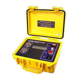
Model 8500 is a lightweight, rugged, portable digital transformer ® ratiometer designed for onsite testing of power, potential and current trans- formers. Operation of the Model 8500 is fully automatic. No user calibra- tion, range selection, hand cranking or tedious balancing is required. During each test cycle, the DTR automatically checks for: ®... -
Page 8: Control Features
Control Features TRANSFORMER RATIOMETER MODEL 8500 CHARGING CONTRAST TEST POWER 1. Display 2. Battery Charge Indicator 3. AC Power Inlet 4. Line Fuse Tray 5. Display Contrast Adjustment 6. TEST Push button 7. Main Power Switch 8. Low-side “X” cable connector (secondary) 9. High-side “H” cable connector (primary) Digital Transformer Ratiometer DTR Model 8500 ®... -
Page 9: Specifications
Charging Time: 14 hrs typical, C/10 rate Line Fuse: 115V: 1.0A, 5 x 20mm, slow acting 230V: 0.5A, 5 x 20mm, slow acting * 23°C ± 5°C, 50 to 70% RH, full battery charge, no external fields or noise. Digital Transformer Ratiometer DTR Model 8500 ®... -
Page 10: Mechanical
*All specifications are subject to change without notice Cable Identification RED BOOT "H" IDENTIFIER 5 PIN CONNECTOR H CABLE SET "H" IDENTIFIER BLACK BOOT RED BOOT "X" IDENTIFIER 3 PIN CONNECTOR X CABLE SET "X" IDENTIFIER BLACK BOOT Digital Transformer Ratiometer DTR Model 8500 ®... -
Page 11: Operation
CHAPTER 4 OPERATION WARNING: The Digital Transformer Ratiometer DTR Model 8500 ® is designed for use on non-energized (“dead”) transformers only. Make sure the test sample is completely disconnected from AC power and is fully discharged. Conducting a Test 1. Connect the DTR test cables in the proper manner to a non-energized ®... -
Page 12: Vt/Pt
BLACK BLACK BLACK BLACK Note: Unlike other instruments, the DTR Model 8500 does not ® impose polarity restrictions or “forced” auto-connections, thus there are several valid hookups and virtually all transformer configu- rations can be tested. In all tests, a negative sign preceding the displayed ratio indicates phase reversal (inverted polarity) of the sensed X signal relative to the excitation signal at H. In using the... -
Page 13: Vt/Pt Testing
Excitation current will be displayed. 5. Once test results are recorded, press the TEST button to reset for the next test. This routine may be repeated as many times as needed without powering down the unit. Digital Transformer Ratiometer DTR Model 8500 ®... -
Page 14: Vt Test Mode Flow Chart
Version XXX 1999 Indicates version of Turn Unit On Chauvin Arnoux Internal Firmware ® AEMC Instruments Model Identification ® Model 8500 Replaces Above Indication ® AEMC Instruments when Batteries Need Low Battery Recharging Indication of PT/VT Test Mode Selected Mode... -
Page 15: Vt/Pt Excitation Current
H winding exhibits much higher impedance than its associated X winding. 4.3.5 VT/PT Continuity Test The Continuity Test function of the DTR Model 8500 serves as a useful ® means of identifying open primary and secondary windings, open circuit breakers, and blown fuses. When selected, the DTR alternately checks ®... -
Page 16: Ct Example Connections
As in VT/PT Test Mode, this routine may be repeated as many times as needed without powering down the unit. The CT Test Mode remains active until the unit is powered down. Digital Transformer Ratiometer DTR Model 8500 ®... -
Page 17: Ct Test Mode Flow Chart
Indicates version of TEST Button Chauvin Arnoux Internal Firmware Depressed ® AEMC Instruments Hold TEST Button Model Identification ® Model 8500 Replaces Above Indication ® AEMC Instruments Hold TEST Button when Batteries Need Low Battery Recharging Indication of Release TEST Button... -
Page 18: Displayed Messages
Operation mode used in VT/PT testing, power-up default mode VT/PT Test Mode Ready Indicates system ready for VT/PT testing CT Test Mode Selected Indicates user selection of CT Test Mode. Mode selected by depressing and holding TEST button during power-up sequence. Digital Transformer Ratiometer DTR Model 8500 ®... -
Page 19: Power Supply
Check H cable connector at DTR front panel. ® Power Supply The DTR Model 8500 may be used for up to 10 hours on fully charged ® NiCd batteries. The DTR may also be line supplied during measurements. ® In this mode the DTR also recharges the NiCd batteries. -
Page 20: Changing Power Supply Setting From 115V To 230V Or 230V To 115V
115V = 1 A, 230V = 0.5A 7. Carefully reinstall instrument into the case and fasten bottom screws. 8. Remove old voltage label. Affix input voltage label (115V or 230V) under the AC power inlet. Digital Transformer Ratiometer DTR Model 8500 ®... -
Page 21: Tips For Making Precise Ratio Measurements
X , and (separately) H to X , a 1:1 BLACK BLACK transformer is simulated. Operation of the DTR in this configuration ® should yield a ratio very nearly equal to 1.000. If it does not, the DTR ® require repair or calibration. 1 : 1 BLACK BLACK CONNECTIONS EQUIVALENT Digital Transformer Ratiometer DTR Model 8500 ®... -
Page 22: Polyphase Connections
HIGH VOLTAGE LOW VOLTAGE TYPE RATIO WINDING WINDING WINDING WINDING 1 Ø 1 Ø ∆ ∆ ∆ ∆ √ ∆ H • ∆ √ H • ∆ √ X • ∆ √ X • Digital Transformer Ratiometer DTR Model 8500 ®... -
Page 23: Maintenance
CHAPTER 5 MAINTENANCE Use only factory specified replacement parts. AEMC will not be held ® responsible for any accident, incident, or malfunction following a repair done other than by its service center or by an approved repair center. WARNING: To avoid electrical shock, do not perform any service other than the operating instructions contained in this manual, unless you are qualified to do so. -
Page 24: Repair And Calibration (North/South America, Australia, New Zealand)
If the instrument is returned for calibration, we need to know if you want a standard calibration, or a calibration traceable to N.I.S.T. (Includes calibration certificate plus recorded calibration data). ® ® Chauvin Arnoux , Inc. d.b.a. AEMC Instruments 15 Faraday Drive • Dover, NH 03820 USA Tel: (800) 945-2362 (Ext. 360) (603) 749-6434 (Ext. 360) Fax: (603) 742-2346 or (603) 749-6309 repair@aemc.com... -
Page 25: Repair And Calibration (Europe, Asia, Africa)
CHAUVIN ARNOUX, SCA. 190, rue Championnet 75876 Paris Cedex 18 - France Tel: (33) 1 44 85 44 57 Fax: (33) 1 46 27 95 59 www.chauvin-arnoux.com Digital Transformer Ratiometer DTR Model 8500 ®... -
Page 26: Limited Warranty
Limited Warranty The Model 8500 is warranted to the owner for a period of two years from the date of original purchase against defects in manufacture. This limited warranty is given by AEMC Instruments, not by the distributor from whom it was ®... -
Page 27: Español
4.4.1 Ejemplo de Conexión CT ...........39 4.4.2 Prueba CT ..............39 4.4.3 Diagrama de Flujo del Mode de Prueba CT ....40 4.5 Mensajes Mostrados ...............41 4.6 Alimentación ................42 4.7 Cambiar el Voltaje de la Fuente de Poder de 115V a 230V o de 230V a 115V ..........43 4.8 Consejos para Hacer Mediciones de Razón Precisas ....44 Medidor de Razón de Transformador Digital DTR Modelo 8500 ®... - Page 28 4.9 Prueba de Razón 1:1 ..............45 4.10 Polyphase Connections ............46 5. MANTENIMIENTO ................. 47 5.1 Reparación y Calibración ............47 5.2 Asistencia técnica y venta ............48 5.3 Garantía Limitada ..............48 5.4 Garantía de Reparación ............48 Medidor de Razón de Transformador Digital DTR Modelo 8500 ®...
-
Page 29: Introducción
• El Medidor de Razón de Transformador Digital DTR Modelo ® 8500 está diseñado para ser usado en transformadores no- energizados solamente. Asegúrese que el equipo a probar está completamente desconectado de la fuente de alimenta- ción AC y está totalmente descargado. • Sólo personal calificado debería usar el Modelo 8500. -
Page 30: Símbolos Eléctricos Internacionales
El Medidor de Razón de Transformador Digital DTR 8500, ajustado ® en fábrica para 230V, 50/60Hz (Cat. #2116.21) incluye baterías NiCd (instaladas), cable de alimentación con extremos desnudos (sin enchufe), conjunto de cables de prueba de 15 pies en un estuche de transporte, tarjeta de garantía & manual de usuario. -
Page 31: Accesorios
230V y placa principal) ......Cat. #2118.53 Fusible, conjunto de 5, 1A, ≥125V (5 x 20mm, acción lenta, sólo para unidades de 115V) ..Cat. #2118.54 Fusible, conjunto de 5, 4A ≥125V ........Cat. #2118.55 (5 x 20mm, acción lenta) Medidor de Razón de Transformador Digital DTR Modelo 8500 ®... -
Page 32: Presentación
CAPITULO 2 PRESENTACIÓN Descripción El DTR Modelo 8500 es un medidor de razón de transformador digital portátil, ® robusto y liviano diseñado para la prueba en terreno de transformadores de potencia, de voltaje y de corriente. La operación del DTR Modelo 8500 es ® totalmente automática. No requiere calibración, selección de rango, uso de manivela o un balanceo tedioso por parte del usuario. -
Page 33: Descripción Del Aparato
Descripción del Aparato TRANSFORMER RATIOMETER MODEL 8500 CHARGING CONTRAST TEST POWER 1. Display 2. Indicador de Carga de la Batería 3. Entrada de Alimentación AC 4. Porta Fusible de Alimentación 5. Ajuste de Contraste del Display 6. Botón Pulsador de PRUEBA 7. Interruptor de Alimentación 8. Conector de Cable “X” lado bajo (secundario) 9. Conector de Cable “H” lado alto (primario) Medidor de Razón de Transformador Digital DTR Modelo 8500 ®... -
Page 34: Especificaciones
115V: 1.0A, 5 x 20mm, acción lenta 230V: 0.5A, 5 x 20mm, acción lenta * 23°C ± 5°C, 50 a 70% HR, batería cargada totalmente, sin campos externos o ruido. Medidor de Razón de Transformador Digital DTR Modelo 8500 ®... -
Page 35: Mecanicas
Identificador “H” Conector de 5 Patas Conjunto de Cables “H” Identificador “H” Capuchón Negro Capuchón Rojo Identificador “X” Conector de 3 Patas Conjunto de Cables “X” Identificador “X” Capuchón Negro Medidor de Razón de Transformador Digital DTR Modelo 8500 ®... -
Page 36: Utilización
CAPITULO 4 UTILIZACIÓN ADVERTENCIA: El Medidor de Razón de Transformador Digital Modelo 8500 está diseñado para ser usado en transformado- ® res no-energizados solamente. Asegúrese que el equipo a probar está completamente desconectado de la fuente de alimentación AC y está totalmente descargado. Para realizar una prueba 1. Conecte los cables de prueba del DTR a un transformador no-ener- ®... -
Page 37: Vt/Pt
H NEGRO H NEGRO X NEGRO X NEGRO Nota: A diferencia de otros instrumentos, el DTR Modelo 8500 no ® impone restricciones de polaridad o auto-conexiones “obligadas”, luego hay varios tipos de conexiones válidas y se puede probar vir- tualmente todas las configuraciones de transformadores. En todas las pruebas, un signo negativo que precede la razón mostrada... -
Page 38: Prueba Vt/Pt
Razón y la Corriente de Excitación. 5. Una vez que los resultados de la prueba han sido registrados, pulse el botón [TEST] para reiniciar para la próxima prueba. Esta rutina puede ser repetida tantas veces como sea necesario sin apagar el instrumento. Medidor de Razón de Transformador Digital DTR Modelo 8500 ®... -
Page 39: Diagrama De Flujo Del Modo De Prueba Vt/Pt
1999 Encienda la Unidad del Programa de Chauvin Arnoux Instrucciones Interno ® AEMC Instruments Identificación del Modelo ® Model 8500 Reemplaza el Mensaje ® de Arriba cuando las AEMC Instruments Baterías Necesitan Low Battery ser Recargadas Indicación del PT/VT Test Mode... -
Page 40: Corriente De Excitación Vt/Pt
Esto es normal y se produce directamente por el hecho que en la mayoría de los transformadores que bajan voltaje, el bobinado H presenta una impedancia mucho más alta que su bobinado X asociado. 4.3.5 Prueba de Continuidad VT/PT La función de Prueba de Continuidad del DTR Modelo 8500 sirve como ® un medio útil para identificar bobinados primarios y secundarios abiertos, desconectadores abiertos, y fusibles quemados. Cuando se lo selecciona, el DTR comprueba alternativamente la continuidad de sus cables X y de ®... -
Page 41: Ejemplo De Conexión Ct
Al igual que en el Modo de Prueba VT/PT, esta rutina puede ser repe- tida tantas veces como sea necesario sin apagar la unidad. El Modo de Prueba CT permanece activo hasta que se apaga la unidad. Medidor de Razón de Transformador Digital DTR Modelo 8500 ®... -
Page 42: Diagrama De Flujo Del Mode De Prueba Ct
Botón Chauvin Arnoux Instrucciones Interno TEST Presionado ® Mantenga el Botón AEMC Instruments Identificación ® TEST Presionado Model 8500 del Modelo Reemplaza el Mensaje de ® Mantenga el Botón AEMC Instruments Arriba cuando las TEST Presionado Low Battery Baterías Necesitan ser Recargadas Indicación del... -
Page 43: Mensajes Mostrados
VT/PT Test Mode ( Modo de Prueba VT/PT ) Modo de operación utilizado en las pruebas VT/PT, modo preestablecido al encender. VT/PT Test Mode Ready ( Modo de Prueba VT/PT Listo ) Indica que el sistema está listo para la prueba VT/PT. Medidor de Razón de Transformador Digital DTR Modelo 8500 ®... -
Page 44: Alimentación
Revise los cables H por posibles cortocircuitos inadvertidos. Revise los conectores de cables H en el panel frontal del DTR ® Alimentación El DTR Modelo 8500 puede ser usado hasta 10 horas con baterías NiCd ® totalmente cargadas. El DTR también puede ser alimentado desde la ®... -
Page 45: Cambiar El Voltaje De La Fuente De Poder De 115V A 230V O De 230V A 115V
115V = 1 A, 230V = 0.5A 7. Reinstale cuidadosamente el instrumento en la carcasa y asegure los tornillos de su base. 8. Remueva la etiqueta con el antiguo voltaje. Coloque una etiqueta con el nuevo voltaje de entrada (115V o 230V) debajo de la entrada de alimentación AC. Medidor de Razón de Transformador Digital DTR Modelo 8500 ®... -
Page 46: Consejos Para Hacer Mediciones De Razón Precisas
No se requiere en la mayoría de los transformadores de derivación variable ni en los reguladores. • Al probar transformadores polifásicos, tenga en mente que en algunos casos, las razones medidas deben ser multiplicadas o divididas por √3. Refiérase al § 4.10 para los diagramas de conexiones polifásicas y las ecuaciones de razón asociadas. Medidor de Razón de Transformador Digital DTR Modelo 8500 ®... -
Page 47: Prueba De Razón 1:1
1.000. Si no se obtiene, el DTR ® puede necesitar reparación o calibración. 1 : 1 ROJO ROJO NEGRO NEGRO CONEXIONES EQUIVALENTE Medidor de Razón de Transformador Digital DTR Modelo 8500 ®... -
Page 48: Polyphase Connections
VOLTAJE ALTO VOLTAJE BAJO ALTO BAJO 1 Ø 1 Ø ∆ ∆ ∆ ∆ √ ∆ H • ∆ √ H • ∆ √ X • ∆ √ X • Medidor de Razón de Transformador Digital DTR Modelo 8500 ®... -
Page 49: Mantenimiento
CSA# por fuera del embalaje. Si el instrumento es mandado para calibración, necesitamos saber el modelo de calibración que desea, calibración estándar o calibración para N.I.S.T. (Incluye certificado de calibración mas la informa- ción recogida al ser calibrado). ® ® Chauvin Arnoux , Inc. d.b.a. AEMC Instruments 15 Faraday Drive • Dover, NH 03820 USA Tel: (603) 749-6434 (Ext. 360) Fax: (603) 742-2346 or (603) 749-6309 repair@aemc.com (Contacte su distribuidor autorizado) El coste por reparación, calibración estándar, y calibración N.I.S.T. están disponibles. -
Page 50: Asistencia Técnica Y Venta
AEMC Instruments. Para un mayor detalle de la cobertura de la garantía y registracion, vaya a www.aemc.com. - Page 52 08/08 99-MAN 100150 v8 Chauvin Arnoux , Inc. d.b.a. AEMC Instruments ® ® 15 Faraday Drive • Dover, NH 03820 USA • Phone: (603) 749-6434 • Fax: (603) 742-2346 www.aemc.com...
Need help?
Do you have a question about the 8500 and is the answer not in the manual?
Questions and answers