Table of Contents
Advertisement
Quick Links
Download this manual
See also:
Instruction Manual
Advertisement
Table of Contents

Related Manuals for AOR SR2000A

Summary of Contents for AOR SR2000A
- Page 1 ® SR2000A FREQUENCY MONITOR INSTRUCTION MANUAL AOR, LTD.
-
Page 2: Table Of Contents
Connections -------------------------------------------------------------------------------------------- 9 Power Switch ------------------------------------------------------------------------------------------- 9 Start up ------------------------------------------------------------------------------------------- 9 Powering down --------------------------------------------------------------------------------- 9 Operations of the SR2000A ---------------------------------------------------------------------- 9 Display ---------------------------------------------------------------------------------------------- 9 Key commands ---------------------------------------------------------------------------------- 12 6 Monitoring Modes --------------------------------------------------------------------------------------- 13 Basic operations – VFO mode (manual mode) ------------------------------------------- 13... - Page 3 10-4-3 FFT search results --------------------------------------------------------------------------- 44 11 Delete menu ---------------------------------------------------------------------------------------------- 46 12 Computer control information ---------------------------------------------------------------------- 47 12-1 Command list ------------------------------------------------------------------------------------ 49 12-2 Command details ------------------------------------------------------------------------------- 50 13 Specifications -------------------------------------------------------------------------------------------- 60 14 Limited warranty ----------------------------------------------------------------------------------------- 61...
-
Page 4: Index
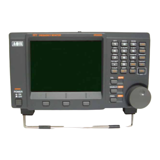
The result is a compact color spectrum display monitor that’s ultra-sensitive, incredibly fast, yet easy to use. The SR2000A is perfect for base, mobile or field use and can also be used in combination with a personal computer. -
Page 5: Power Requirements
1-3 Power requirements The SR2000A may be provided with a suitable AC/DC power unit. The SR2000A is designed for operation from a nominal 12 V DC regulated power supply (12 to 14 V is acceptable), which should be capable of supplying a minimum of 1.5 amp continuous, ideally a 2 amp power supply unit should be used. -
Page 6: Control And Functions
2-1 Front panel controls The front panel of the SR2000A is dominated by the large color LCD. Controls are ‘grouped’ to assist efficient operation; there are a total of 26 keys in addition to the power on/off switch and the rotary dial encoder. - Page 7 “FUNC” key located at the top right of the control keys, then press respective key. 5. Special function keys Three (3) special function keys are provided with the SR2000A. Those keys are to be used for setting the center frequency, squelch level and volume control (audio output).
-
Page 8: Rear Panel
2-2 Rear panel This is the antenna input for the SR2000A. The connector is a BNC type. Use 50ohm cable to connect your antenna. DC 12V The supplied power unit is terminated with a center positive (+) polarity connector. PHONES Headphone jack (3.5mm stereo type):... - Page 9 REMOTE 1 USB interface connector. Use a USB-A to USB-B cable (not supplied) to connect your PC. The USB driver can be downloaded from the following URL: http://www.ftdichip.com/ftdrivers.htm Click “VCP Drivers”, then select the device number “FT232B” REMOTE 2 RS-232C serial interface connector. Use a DB-9 serial cable to connector your PC. (Caution: The REMOTE 1 and the REMOTE 2 cannot be used simultaneously.) INTERNAL SPEAKER (TOP PANEL) Internal speaker...
-
Page 10: Connections
“beep” sound. This start-up sequence is a factory default and cannot be altered. Powering down To switch off the SR2000A, press the power switch a second time, the switch releases and the unit is powered down. Interfering with the regular powering down process might damage the SR2000A. - Page 11 The SR2000A displays up to 40 MHz of spectrum bandwidth (20MHz or 40MHz selectable) in the wide span mode. To select the wide span mode, set the SR2000A to the VFO mode. Then press the FUNC key. A soft key menu will appear on the bottom of the LCD.
- Page 12 The RFU information is displayed on the top of the LCD screen, and displays the Monitored frequency, receive mode, frequency step size, signal strength, RF amplifier status, and attenuator level. (7) Operating Mode (OP) Three operating modes are available with the SR2000A. Spectrum : Spectrum Analyzer mode StepReso.: Step Resolution mode Channel :...
-
Page 13: Key Commands
FUNC icon appears on the top left corner of the screen. (15) VFO (Variable Frequency Oscillator) The SR2000A has a nine (9) VFO system, identified from VFO-A to VFO-I. Displayed on the previous page example is VFO-A. -
Page 14: Monitoring Modes
Select the video display mode 6 Monitoring Modes 6-1 Basic operations – VFO mode (manual mode) This describes the SR2000A in the most commonly used VFO mode. This mode allows manual input of the center frequency. 6-1-1 Setting up the monitoring frequency... - Page 15 RECEIVE MODE FREQUENCY STEP MONITOR FREQUENCY By pressing the soft key below CENTER FREQ. on the LCD, the center frequency is selected and can be adjusted using the dial knob. Key entry of the main frequency: Enter the frequency in MHz format using the numeric keys, then press the MHz key to complete.
- Page 16 Press the FREQ key to reassign the frequency control to the dial knob. Start and End Frequency Input In the VFO mode, the step key enables the step size for tuning the receiver to be customized. Pressing the STEP key will select the tuning step in reverse contrast. Then rotate the dial to select a new step size.
-
Page 17: Setting Up The Receive Mode
To change the receive mode, press the MODE key. The receive mode icon will be selected (in reverse contrast) on the LCD to confirm that the mode select menu has been activated. The following 4 modes are available with the SR2000A: NFM, WFM, SFM, AM. RECEIVE MODE Receive mode setup: Press the MODE key. -
Page 18: Squelch Control
To undo the mute, repeat the above steps. 6-1-4 Squelch control The SR2000A has two (2) squelch types, NSQ (Noise Squelch) and LSQ (Level Squelch). Pressing the SQUELCH key allows you to select one or the other. Then adjust the squelch level with the dial knob, from level 00 to 72. -
Page 19: Rf Attenuator And Preamplifier Settings
Squelch level control: Press the SQUELCH key. Rotate the dial knob to select the desired volume level. The squelch level can be set from level 00 to 72. 6-1-5 RF attenuator and preamplifier settings The ATT key selects the antenna attenuation level (by reverse contrast). Using the dial Knob, you can choose between 0dB, 10dB, 20dB. -
Page 20: Input Sensitivity (Amplitude)
SQUELCH key for one second. 6-1-7 Input sensitivity (amplitude) This feature refers to the setup of the input sensitivity level of the SR2000A. There are 6 different levels of input sensitivity between 0dBm and –50dBm in 10dB steps. -
Page 21: Waterfall Display Function
RBW filter. 6-1-9 Waterfall display function The SR2000A is equipped with a waterfall function which can display the variation of signal strengths in conjunction with the time lapsed (as sweeps progress). Sixteen different colors are employed dependent on signal strength, in the shape of waterfall. -
Page 22: Selecting The Operation Modes
Signal display is scrolling downwards as time progresses. 6-1-10 Selecting the operation modes The SR2000A has 3 different operation modes which can be selected by pressing the FUNC key followed by the 0 key. The soft keys below the screen give you access to each corresponding mode. -
Page 23: Operation Modes
6-2 Operation Modes There are three (3) operation modes with your SR2000A. They are the Spectrum Analyzer Mode, Step Resolution Mode, and the Channel Scope Mode. To go to the Spectrum Analyzer Mode, press the FUNC key, then press the 0 key. -
Page 24: Step Resolution Mode
Start and End frequencies The START and End frequency can be entered in the same manner as the center frequency entry using the assigned soft keys, numeric keys and MHz key. The dial knob is not valid for the entry. [Note] The CF = MF principle In the spectrum analyzer mode and the step resolution mode,... -
Page 25: Channel Scope Mode
Effective frequency coverage The center frequency (CF) must be within the frequency coverage of the SR2000A (25MHz ~3000MHz). If exceeded, monitoring is not possible. Display frequency span (MHz) is obtained by the following formula: CF +/- (display step x 160) In the above example, the center frequency is 122.50MHz. -
Page 26: Marker Functions
6-3 Marker functions The SR2000A has a marker function. The marker is often used to obtain the value of a frequency of interest. In addition to the instantaneous reading, it provides peak detection and continuous peak detection. Press the FUNC key followed by the MK.F key to place the SR2000A in marker mode operation. - Page 27 Peak detection (Peak : PEK) This feature is used to detect the most powerful signal while sweeping the frequency range. Press the PEAK soft key, which in turn requests a trigger level. You need to specify what level is required. Enter the trigger level via the numeric keys. Only signals which are stronger than the trigger level you specified will then be subject to peak detection.
-
Page 28: Calculation Function
[Note] [MK.F] key functions: In the spectrum analyzer and step resolution mode, pressing the MK.F key forces the marker frequency to become the center frequency. In the channel scope mode, pressing the MK.F key will not become the center frequency. The MK.F key cannot be used in the Peak Detection mode. -
Page 29: Video Monitor Function
The value showed on the dB axis at 50 MHz will be the average of the three values for the 3 frequencies. 6-5 Video monitor function The SR2000A has a built-in video decoder and supports NTSC, PAL, and SECAM format. The video signal format is automatically detected. -
Page 30: Configuration
2. Select NORMAL or REVERSE to descramble video signal. 7 Configuration In this chapter, we learn how to set fundamental operating parameters of the SR2000A. To access the SR2000A’s configuration menu, press the FUNC key, then press the 9 key. - Page 31 Use the UP and DOWN soft key to move from one section to the other. Once the desired selection appears in reverse contrast, rotate the dial knob to do any changes as needed, and press the MHz key to go to the next section. Be aware that your changes have not been saved so far! Once you have finished the desired configuration changes, press and hold the MHz key for one second to save all your settings and return to the screen you were at before entering the configuration.
- Page 32 Default setting is AUTO. To receive in SECAM format, select AUTO or PAL. BEEP The SR2000A emits confirmation “beeps” when the keypad is used. Default is ON. Beep level is not adjustable. PLOT (Drawing mode setup) Set to PAINT as default. The OUTLINE setting has the monitor only drawing the outline of the displayed wave.
-
Page 33: Resetting The Sr2000A
AF GAIN (volume) and SQUELCH. To return to the configuration menu, press the FREQ. key, 7-1 Resetting the SR2000A If you wish the SR2000A to return to the factory default settings, perform the following steps: 1. Turn the SR2000A power off. -
Page 34: Memory Scan
Memory read indicator Memory bank and channel Memory description text First, select the desired memory bank and channel using the numeric keys. The first single digit number will be the bank and second 2 digit number will be the channel. If you enter an incorrect parameter, an error beep will sound. -
Page 35: Programming The Memory
INDICATOR FOR SELECTED FREQUENCY This memory scan behavior depends on the squelch delay time (between squelch closing and scan restart) set in the “configuration menu” in paragraph 7. If you wish to bypass the configured delay settings, press the MHz key to force detection to the next higher frequency, or press the KHz key to the next lower frequency. -
Page 36: Memory Text Input
Bank channel (BANK-CH) An available bank and memory channel are automatically selected (bank 0 by default, as long as there are available channels). It is possible to choose another bank/channel with the numeric keys. Frequency (FREQ) The frequency automatically displayed is the one which was active in your previous VFO mode. -
Page 37: Selected Memory Scanning
2 key, the assigned characters come as follows: ….. When a different key is pressed, the cursor goes automatically to the next character. [Note]: The text input method of the SR2000A is very similar to cellular phones. Saving your changes To save your text input, press the MHz key, which will bring you to the Memory Programming Page (previous paragraph 8-3). - Page 38 In this example, memory “mem 0-03” is chosen. Accessing a selection (S SET) Once you are in the Memory Read mode screen as plotted above, the selected memory Scanning mode can be accessed by pressing the FUNC key followed by the 6 key. The SEL icon will appear on the top of the screen.
-
Page 39: Priority Monitor
The INTERVAL value determines how long the SR2000A will wait between cycles before re-sampling the priority frequency for activity. If no activity is detected, the receiver returns to its previous state. Note: When the SR2000A switches to the priority channel, a switching noise may be heard. However, it is normal. -
Page 40: Frequency Offset
PRIORITY FUNCTION INDICATOR 9 Frequency Offset This function enables the received frequency to be quickly shifted by a pre-determined value which makes it easy to track duplex transmissions or check repeater inputs/outputs. Setting up an offset frequency The frequency offset menu can be accessed by pressing the FUNC key, followed by a two second press of the . -
Page 41: Normal Search And Fft Search
A flashing DUP icon will show the offset frequency is being monitored. 10 Normal Search and FFT Search The SR2000A has 40search banks (01-40) to which can be applied Normal Search as well as FFT Search. In both cases, search bank usage is similar. -
Page 42: Normal Search
To save all selections: Press and hold the MHz key for two seconds. After the search bank set up is completed, the SR2000A will start the normal search. To leave this screen without saving any changes: Press the CLR key. -
Page 43: Frequency Pass Setup
If you press again the FUNC key and 2 keys while the search is active (as plotted above), You will enter the Nonstop search mode. The SR2000A will continuously search in the frequency range you have specified. You can exit that mode by repeating the same steps. As the screen can only display 30 frequencies on the screen, new frequencies will overwrite the older ones. -
Page 44: Fft Search
While in the Search mode, press the FUNC key followed by the MODE key to access the PASS mode, then as in the plot above, the frequency 147.86 MHz is selected from the search result list by the white triangle cursor (with the UP or DOWN soft keys), and set as a PASS FREQUENCY by pressing the SET FREQ. -
Page 45: Fft Search Setup
parameters must also be set. FFT Frequency step Threshold level (signal detection level) 10-4-2 FFT search setup To access the FFT search mode, press the FUNC key, then press the 1 key. Search bank selection First select a search bank (two digits) to access and confirm by pressing the MHz key. Frequency step selection Using the dial knob, select an appropriate frequency step. - Page 46 Although this display information is limited to the frequency and signal level colors, the real power of the SR2000A is its possibility to output all these data to a PC interface port in a continuous data stream.
-
Page 47: Delete Menu
(RBW) is automatically set to 4 KHz. 11 Delete menu The SR2000A allows convenient deletion of search banks, memory banks, memory channels, pass banks and pass frequencies in one single Delete menu. To access the Delete menu function, press the FUNC key, then press the 8 key. -
Page 48: Computer Control Information
Press the CLR key. 12 Computer control information Your SR2000A is fully controllable by PC via the RS-232C serial interface or the USB interface. No specific hardware interface is required, just a straight RS-232C cable or USB-A to USB-B interface cable. - Page 49 In the following example, the DB command has to be followed by a 3 digit number. [Example] The SR2000A will add one or two “0” in order to achieve three digits. DB3<CR> ----- processed as DB003<CR> DB03<CR> ---- processed as DB003<CR>...
-
Page 50: Command List
12-1 Command list Below is the command list for the SR2000A. Each command is explained on the following pages. AF gain RF amp Attenuator Arithmetic average value Back light Beep sound Channel scope mode Center frequency Marker mode Level search Delay time Dial’s automatic return parameter... -
Page 51: Command Details
12-2 Command details AG AF gain Setup: AGn<CR> nnn = 0 ~ 72 Default : 0 Acquisition: AG<CR> Response value : AGgnn (fixed length) AM RF amp Setup: AMn<CR> n = 0 (off), n = 1 (on) Default : 1 Acquisition: AM<CR>... - Page 52 The data will be converted to ASCII code. Therefore, the level data is 320. (Note: When the level data indicates other than 320, the SR2000A is in the channel scope mode. The level data depends on start, step, and end frequencies.)
- Page 53 F0092.9787L-100<SP><CR><LF> /<SP><CR><LF> (Note: The separator (/<SP><CR><LF>) has 320 lines. When the level data indicates other than 320, the SR2000A is in the channel scope mode. The level data depends on the start, step, and end frequencies.) GN Spectrum/Video input sensitivity Setup: GNn<CR>...
- Page 54 GR Select memory list read Acquisition: GRnn<CR> nn = 00 ~ 99 (channel number) nn = %% (all channels) nn must be in two digits format HV Video output horizontal position Setup: HVn<CR> n = 0~49 n = 0 (left end of the screen) Default : 16 Acquisition: HV<CR>...
- Page 55 MC Change marker frequency to center frequency (CF) Setup: MC<CR> Command valid only for setup. MD Demodulation mode Setup: MDn<CR> n = 0 (NFM) n = 1 (WFM) n = 2 (SFM) n = 3 (AM) Default : 0 Acquisition: MD<CR> Response value : MDn ME Median value Setup: MEn<CR>...
- Page 56 nn = 00 ~ 99 (channel number) GAn : n referes to command GA. It is possible to omit it, in which case it is specified by GA0. RFnnnn.nnnn (MHz) MDn : n refers to command MD. ATn : n refers to command AT. It is possible to omit it, in which case it is specified by AT0.
- Page 57 nn = 00 ~ 99 (memory channel) Acquisition: PP<CR> Response value : PPmnn PQ Priority function switch Setup: PQn<CR> n = 0 (off) n = 1 (on) Acquisition: PQ<CR> Response value : PQn PR Pass frequency read Acquisition: PRmm<CR> mm = 01 ~ 40 (search bank) Response value : If no frequency is registered in the PRmm nnnn.nnnn (MHz) list, the only response will be “OK”.
- Page 58 SM MXmnn GAn RFmmmmmnnnn STmmmnnn MDn SQn ATn AMn TMxx…: (Unit: RF: in Hz, ST: in Hz) In the normal search mode: SSnn RFmmmmmnnnn STmmmnnn MDn SQn ATn AMn TTxx… (Unit: RF: in Hz, ST: in Hz) In the FFT search mode: FFmm TSnn TT-kk (Refer to command FF) In the VFO mode: Vx RFmmmm.nnnn STmmm.nn MDn ATn AMn...
- Page 59 SQ Squelch Setup: SQn<CR> n = 0 (noise squelch) n = 1 (level squelch) Default : 0 Acquisition: SQ<CR> Response value : SQn SR Search bank read out Setup: SRnn<CR> nn = 01 ~ 40 (search bank number) Response value : SRnn SLnnnnnnnnnn SUnnnnnnnnnn MDn SQn ATn AMn TTxx….
- Page 60 nn = 5 (9KHz) nn = 6 (10KHz) nn = 7 (12.5KHz) nn = 8 (20KHz) nn = 9 (25KHz) nn = 10 (30KHz) nn = 11 (50KHz) nn = 12 (100KHz) Default : 6 (10KHz) Acquisition: TS<CR> Response value : TSnn TT Signal bar level Setup: TT-nn<CR>...
-
Page 61: Specifications
13 Specifications Model: SR2000A Frequency range: 25 ~ 3,000 MHz (Cellular blocked for US consumer version) Receive modes: AM/NFM/WFM/SFM/APCO25(P25) Optional Receiver configuration: Triple conversion super heterodyne IF frequency: : 255.3 / 744.3 MHz : 10.7 MHz : 455 KHz Sensitivity: 25MHz ~ 225MHz: NFM: 0.35uV (12dB SINAD) -
Page 62: Limited Warranty
AOR USA, Inc. (AOR) warrants its products as described below: AOR will repair or exchange equipment as a result of defects in parts or workmanship for a period of one year from the date of original retail purchase from an authorized AOR dealer. - Page 63 We suggest attaching your purchase receipt to this half of the warranty information sheet and that you keep this information in a secure location. AOR Model Number __________________________ Serial Number _______________________________ Dealer Name ________________________________ Purchase Date _______________________________ AOR, LTD. 2-6-4, Misuji, Taitok-Ku Tokyo, 111-0055, Japan http://www.aorja.com...
Need help?
Do you have a question about the SR2000A and is the answer not in the manual?
Questions and answers