GE MiCOM P40 Agile Technical Manual
Feeder management ied
Hide thumbs
Also See for MiCOM P40 Agile:
- Technical manual (962 pages) ,
- Technical manual (623 pages) ,
- Technical manual (802 pages)

Related Manuals for GE MiCOM P40 Agile


Summary of Contents for GE MiCOM P40 Agile
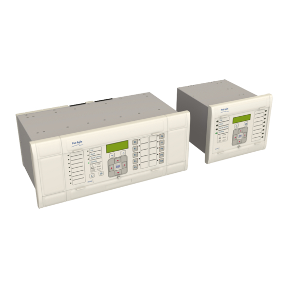
- Page 1 GE Energy Connections Grid Solutions MiCOM P40 Agile P141, P142, P143, P144, P145 Technical Manual Feeder Management IED Hardware Version: J Software Version: 52 Publication Reference: P14xEd1-TM-EN-1...
-
Page 3: Table Of Contents
Contents Chapter 1 Introduction Chapter Overview Foreword Target Audience Typographical Conventions Nomenclature Product Scope Ordering Options Features and Functions Protection Functions Control Functions Measurement Functions Communication Functions Compliance Functional Overview Chapter 2 Safety Information Chapter Overview Health and Safety Symbols Installation, Commissioning and Servicing Lifting Hazards Electrical Hazards... - Page 4 Contents P14x 4.1.7 Programable LEDs Rear Panel Boards and Modules PCBs Subassemblies Main Processor Board Power Supply Board 6.4.1 Watchdog 6.4.2 Rear Serial Port Input Module - 1 Transformer Board 6.5.1 Input Module Circuit Description 6.5.2 Transformer Board 6.5.3 Input Board Standard Output Relay Board IRIG-B Board Fibre Optic Board...
- Page 5 P14x Contents Password Entry Processing Alarms and Records Menu Structure Changing the Settings Direct Access (The Hotkey menu) 3.9.1 Setting Group Selection Using Hotkeys 3.9.2 Control Inputs 3.9.3 Circuit Breaker Control 3.10 Function Keys Date and Time Configuration Using an SNTP Signal Using an IRIG-B Signal Using an IEEE 1588 PTP Signal Without a Timing Source Signal...
- Page 6 Contents P14x Selective Logic Diagram Timer Setting Selection Negative Sequence Overcurrent Protection Negative Sequence Overcurrent Protection Implementation Non-Directional Negative Sequence Overcurrent Logic Composite Earth Fault Start Logic Directional Element 9.4.1 Directional Negative Sequence Overcurrent Logic Application Notes 9.5.1 Setting Guidelines (Current Threshold) 9.5.2 Setting Guidelines (Time Delay) 9.5.3...
- Page 7 P14x Contents 15.3 Second Harmonic Blocking Logic (SEF Input) 15.4 Application Notes 15.4.1 Setting Guidelines Load Blinders 16.1 Load Blinder Implementation 16.2 Load Blinder Logic Neutral Admittance Protection 17.1 Neutral Admittance Operation 17.2 Conductance Operation 17.3 Susceptance Operation Busbar Protection 18.1 Buswire Supervision Chapter 7...
- Page 8 Contents P14x Chapter 9 Current Transformer Requirements Chapter Overview CT requirements Phase Overcurrent Protection 2.1.1 Directional Elements 2.1.2 Non-directional Elements Earth Fault Protection 2.2.1 Directional Elements 2.2.2 Non-directional Elements SEF Protection (Residually Connected) 2.3.1 Directional Elements 2.3.2 Non-directional Elements SEF Protection (Core-Balanced CT) 2.4.1 Directional Elements 2.4.2...
- Page 9 P14x Contents 7.2.3 Sensitive Overvoltage Blocking Logic Chapter 11 Frequency Protection Functions Chapter Overview Frequency Protection Overview Frequency Protection Implementation Underfrequency Protection Underfrequency Protection Implementation Underfrequency Protection Logic Application Notes 3.3.1 Setting Guidelines Overfrequency Protection Overfrequency Protection Implementation Overfrequency Protection Logic Application Notes 4.3.1 Setting Guidelines...
- Page 10 Contents P14x Sensitive Power Protection Implementation Sensitive Power Measurements Sensitive Power Logic Application Notes 4.4.1 Sensitive Power Calculation 4.4.2 Sensitive Power Setting Guidelines Transient Earth Fault Detection Transient Earth Fault Detection Implementation 5.1.1 Transient Earth Fault Detector 5.1.2 Fault Type Detector 5.1.3 Direction Detector Transient Earth Fault Detection Logic...
- Page 11 P14x Contents 5.15 Reset Lckout Alm (Reset Lockout Alarm) 5.16 Reclaim In Prog 5.17 Reclaim Complete Autoreclose Function Alarms AR No Sys Check AR CB Unhealthy AR Lockout Autoreclose Operation Operating Modes 7.1.1 Four-Position Selector Switch Implementation 7.1.2 Operating Mode Selection Logic Autoreclose Initiation 7.2.1 Start Signal Logic...
- Page 12 Contents P14x 4.1.5 Frequency Measurements 4.1.6 Other Measurements Measurement Setup Fault Locator 4.3.1 Fault Locator Settings Example Opto-input Time Stamping CB Condition Monitoring Application Notes 5.1.1 Setting the Thresholds for the Total Broken Current 5.1.2 Setting the thresholds for the Number of Operations 5.1.3 Setting the thresholds for the Operating Time 5.1.4...
- Page 13 P14x Contents 3.3.1 Setting Guidelines Trip Circuit Supervision Trip Circuit Supervision Scheme 1 4.1.1 Resistor Values 4.1.2 PSL for TCS Scheme 1 Trip Circuit Supervision Scheme 2 4.2.1 Resistor Values 4.2.2 PSL for TCS Scheme 2 Trip Circuit Supervision Scheme 3 4.3.1 Resistor Values 4.3.2...
- Page 14 Contents P14x High-Availability Seamless Redundancy (HSR) 5.3.1 HSR Multicast Topology 5.3.2 HSR Unicast Topology 5.3.3 HSR Application in the Substation Rapid Spanning Tree Protocol Self Healing Protocol Dual Homing Protocol Configuring IP Addresses 5.7.1 Configuring the IED IP Address 5.7.2 Configuring the REB IP Address Simple Network Management Protocol (SNMP) SNMP Management Information Bases...
- Page 15 P14x Contents 7.4.10 Time Synchronisation 7.4.11 Power and Energy Measurement Data Formats 7.4.12 MODBUS Configuration IEC 61850 7.5.1 Benefits of IEC 61850 7.5.2 IEC 61850 Interoperability 7.5.3 The IEC 61850 Data Model 7.5.4 IEC 61850 in MiCOM IEDs 7.5.5 IEC 61850 Data Model Implementation 7.5.6 IEC 61850 Communication Services Implementation 7.5.7...
- Page 16 Contents P14x Disabling Physical Ports Disabling Logical Ports Security Events Management Logging Out Chapter 20 Installation Chapter Overview Handling the Goods Receipt of the Goods Unpacking the Goods Storing the Goods Dismantling the Goods Mounting the Device Flush Panel Mounting Rack Mounting Cables and Connectors Terminal Blocks...
- Page 17 P14x Contents Essential Commissioning Equipment Advisory Test Equipment Product Checks Product Checks with the IED De-energised 5.1.1 Visual Inspection 5.1.2 Current Transformer Shorting Contacts 5.1.3 Insulation 5.1.4 External Wiring 5.1.5 Watchdog Contacts 5.1.6 Power Supply Product Checks with the IED Energised 5.2.1 Watchdog Contacts 5.2.2...
- Page 18 Contents P14x 2.5.5 Replacement of the I/O boards Recalibration Changing the battery 2.7.1 Post Modification Tests 2.7.2 Battery Disposal Cleaning Troubleshooting Self-Diagnostic Software Power-up Errors Error Message or Code on Power-up Out of Service LED on at power-up Error Code during Operation 3.5.1 Backup Battery Mal-operation during testing...
- Page 19 P14x Contents Performance of Voltage Protection Functions Undervoltage Protection Overvoltage Protection Residual Overvoltage Protection Negative Sequence Voltage Protection Rate of Change of Voltage Protection Performance of Frequency Protection Functions Basic Overfrequency Protection Basic Underfrequency Protection Advanced Overfrequency Protection Advanced Underfrequency Protection Supervised Rate of Change of Frequency Protection Independent Rate of Change of Frequency Protection Average Rate of Change of Frequency Protection...
- Page 20 Contents P14x 13.4 Corrosive Environments Electromagnetic Compatibility 14.1 1 MHz Burst High Frequency Disturbance Test 14.2 Damped Oscillatory Test 14.3 Immunity to Electrostatic Discharge 14.4 Electrical Fast Transient or Burst Requirements 14.5 Surge Withstand Capability 14.6 Surge Immunity Test 14.7 Immunity to Radiated Electromagnetic Energy 14.8 Radiated Immunity from Digital Communications...
- Page 21 Table of Figures Figure 1: Functional Overview Figure 2: Hardware architecture Figure 3: Exploded view of IED Figure 4: Front panel (60TE) Figure 5: HMI panel Figure 6: Rear view of populated case Figure 7: Terminal block types Figure 8: Rear connection to terminal block Figure 9: Main processor board...
- Page 22 Table of Figures P14x Figure 39: Modification of current pickup level for voltage restrained overcurrent protection Figure 40: Voltage dependant overcurrent logic (Phase A to phase B) Figure 41: Selecting the current threshold setting Figure 42: Cold Load Pickup logic Figure 43: Selective Logic Figure 44:...
- Page 23 P14x Table of Figures Figure 78: Load blinder and angle Figure 79: Load Blinder logic 3phase Figure 80: Load Blinder logic phase A Figure 81: Admittance protection Figure 82: Conductance operation Figure 83: Susceptance operation Figure 84: Simplified busbar representation Figure 85: High Impedance differential protection for busbars Figure 86:...
- Page 24 Table of Figures P14x Figure 118: Condenser bushing system vectors Figure 119: Device connection with resistors and shorting contact Figure 120: Device connection P141/ P142/ P143/ P145 Figure 121: Device connection P144 Figure 122: Negative Sequence Overvoltage logic Figure 123: Sensitive Overvoltage operation logic Figure 124: Sensitive Overvoltage filter mode logic...
- Page 25 P14x Table of Figures Figure 158: AR Initiation inhibit Figure 159: Overall Lockout logic Figure 160: Lockout for protection trip when AR is not available Figure 161: Fault recorder stop conditions Figure 162: CB State Monitoring logic Figure 163: Hotkey menu navigation Figure 164: Default function key PSL Figure 165:...
- Page 26 Table of Figures P14x Figure 198: Redundant Ethernet ring architecture with IED, bay computer and Ethernet switches after failure Figure 199: Dual homing mechanism Figure 200: Application of Dual Homing Star at substation level Figure 201: IED and REB IP address configuration Figure 202: Control input behaviour Figure 203:...
-
Page 27: Chapter 1 Introduction
CHAPTER 1 INTRODUCTION... -
Page 28: Rear Serial Port
Chapter 1 - Introduction P14x P14xEd1-TM-EN-1... -
Page 29: Chapter Overview
P14x Chapter 1 - Introduction CHAPTER OVERVIEW This chapter provides some general information about the technical manual and an introduction to the device(s) described in this technical manual. This chapter contains the following sections: Chapter Overview Foreword Product Scope Features and Functions Compliance Functional Overview P14xEd1-TM-EN-1... -
Page 30: Foreword
Chapter 1 - Introduction P14x FOREWORD This technical manual provides a functional and technical description of General Electric's P141, P142, P143, P144, P145, as well as a comprehensive set of instructions for using the device. The level at which this manual is written assumes that you are already familiar with protection engineering and have experience in this discipline. -
Page 31: Nomenclature
P14x Chapter 1 - Introduction NOMENCLATURE Due to the technical nature of this manual, many special terms, abbreviations and acronyms are used throughout the manual. Some of these terms are well-known industry-specific terms while others may be special product- specific terms used by General Electric. The first instance of any acronym or term used in a particular chapter is explained. -
Page 32: Product Scope
Chapter 1 - Introduction P14x PRODUCT SCOPE The P14x range of feeder management IEDs has been designed for all applications where overcurrent and earth fault protection is required, from distribution to transmission voltage levels. All devices within the range are suitable for solidly-earthed, impedance-earthed, Petersen coil-earthed and isolated systems. -
Page 33: Features And Functions
P14x Chapter 1 - Introduction FEATURES AND FUNCTIONS PROTECTION FUNCTIONS The P14x range of devices provides the following protection functions: ANSI IEC 61850 Protection Function Undercurrent detection (low load) NgcPTOC Negative sequence overcurrent 46BC Broken Conductor ThmPTTR Thermal Overload 50 SOTF Switch onto Fault 50BF RBRF... -
Page 34: Control Functions
Chapter 1 - Introduction P14x ANSI IEC 61850 Protection Function 81RAV DfpPFRC Frequency supervised average rate of change of frequency Load Restoration Rate of change of voltage (dv/dt) Blocking scheme Programmable curves High Impedance Earth Fault CB Monitoring Latching output contacts (Lockout) CONTROL FUNCTIONS Feature IEC 61850... - Page 35 P14x Chapter 1 - Introduction Feature ANSI NERC compliant cyber-security Front RS232 serial communication port for configuration Rear serial RS485 communication port for SCADA control 2nd Additional rear serial communication ports for SCADA control and teleprotection (fibre and copper) (optional) Ethernet communication (optional) Redundant Ethernet communication (optional) Courier protocol...
-
Page 36: Compliance
Chapter 1 - Introduction P14x COMPLIANCE The device has undergone a range of extensive testing and certification processes to ensure and prove compatibility with all target markets. A detailed description of these criteria can be found in the Technical Specifications chapter. P14xEd1-TM-EN-1... -
Page 37: Functional Overview
P14x Chapter 1 - Introduction FUNCTIONAL OVERVIEW 2nd Remote Remote Local Disturbance Fault Records InterMiCOM Comm. Port Comm. Port Communication Record Measurements Self Monitoring 2nd Harmonic Blocking 50N/ 37P/ 67N/67W 49SR 50/51 81U/81O Function 50BF LEDs 27/59 Keys /81R (P145 only) Binary Always Available Feeder Management P14x... - Page 38 Chapter 1 - Introduction P14x P14xEd1-TM-EN-1...
-
Page 39: Chapter 2 Safety Information
CHAPTER 2 SAFETY INFORMATION... - Page 40 Chapter 2 - Safety Information P14x P14xEd1-TM-EN-1...
-
Page 41: Chapter Overview
P14x Chapter 2 - Safety Information CHAPTER OVERVIEW This chapter provides information about the safe handling of the equipment. The equipment must be properly installed and handled in order to maintain it in a safe condition and to keep personnel safe at all times. You must be familiar with information contained in this chapter before unpacking, installing, commissioning, or servicing the equipment. -
Page 42: Health And Safety
Chapter 2 - Safety Information P14x HEALTH AND SAFETY Personnel associated with the equipment must be familiar with the contents of this Safety Information. When electrical equipment is in operation, dangerous voltages are present in certain parts of the equipment. Improper use of the equipment and failure to observe warning notices will endanger personnel. -
Page 43: Symbols
P14x Chapter 2 - Safety Information SYMBOLS Throughout this manual you will come across the following symbols. You will also see these symbols on parts of the equipment. Caution: Refer to equipment documentation. Failure to do so could result in damage to the equipment Warning: Risk of electric shock... -
Page 44: Installation, Commissioning And Servicing
Chapter 2 - Safety Information P14x INSTALLATION, COMMISSIONING AND SERVICING LIFTING HAZARDS Many injuries are caused by: Lifting heavy objects ● Lifting things incorrectly ● ● Pushing or pulling heavy objects Using the same muscles repetitively ● Plan carefully, identify any possible hazards and determine how best to move the product. Look at other ways of moving the load to avoid manual handling. -
Page 45: Ul/Csa/Cul Requirements
P14x Chapter 2 - Safety Information Caution: NEVER look into optical fibres or optical output connections. Always use optical power meters to determine operation or signal level. Warning: Testing may leave capacitors charged to dangerous voltage levels. Discharge capacitors by rediucing test voltages to zero before disconnecting test leads. Caution: Operate the equipment within the specified electrical and environmental limits. -
Page 46: Equipment Connections
Chapter 2 - Safety Information P14x Caution: Digital input circuits should be protected by a high rupture capacity NIT or TIA fuse with maximum rating of 16 A. for safety reasons, current transformer circuits must never be fused. Other circuits should be appropriately fused to protect the wire used. Caution: CTs must NOT be fused since open circuiting them may produce lethal hazardous voltages... -
Page 47: Pre-Energisation Checklist
P14x Chapter 2 - Safety Information Caution: Use a locknut or similar mechanism to ensure the integrity of stud-connected PCTs. Caution: The recommended minimum PCT wire size is 2.5 mm² for countries whose mains supply is 230 V (e.g. Europe) and 3.3 mm² for countries whose mains supply is 110 V (e.g. North America). -
Page 48: Upgrading/Servicing
Chapter 2 - Safety Information P14x Note: For most Alstom equipment with ring-terminal connections, the threaded terminal block for current transformer termination is automatically shorted if the module is removed. Therefore external shorting of the CTs may not be required. Check the equipment documentation and wiring diagrams first to see if this applies. -
Page 49: Decommissioning And Disposal
P14x Chapter 2 - Safety Information DECOMMISSIONING AND DISPOSAL Caution: Before decommissioning, completely isolate the equipment power supplies (both poles of any dc supply). The auxiliary supply input may have capacitors in parallel, which may still be charged. To avoid electric shock, discharge the capacitors using the external terminals before decommissioning. -
Page 50: Regulatory Compliance
Chapter 2 - Safety Information P14x REGULATORY COMPLIANCE Compliance with the European Commission Directive on EMC and LVD is demonstrated using a technical file. EMC COMPLIANCE: 2014/30/EU The product specific Declaration of Conformity (DoC) lists the relevant harmonised standard(s) or conformit assessment used to demonstrate compliance with the EMC directive. - Page 51 P14x Chapter 2 - Safety Information Where: 'II' Equipment Group: Industrial. '(2)G' High protection equipment category, for control of equipment in gas atmospheres in Zone 1 and 2. This equipment (with parentheses marking around the zone number) is not itself suitable for operation within a potentially explosive atmosphere.
- Page 52 Chapter 2 - Safety Information P14x P14xEd1-TM-EN-1...
-
Page 53: Chapter 3 Hardware Design
CHAPTER 3 HARDWARE DESIGN... - Page 54 Chapter 3 - Hardware Design P14x P14xEd1-TM-EN-1...
-
Page 55: Chapter Overview
P14x Chapter 3 - Hardware Design CHAPTER OVERVIEW This chapter provides information about the product's hardware design. This chapter contains the following sections: Chapter Overview Hardware Architecture Mechanical Implementation Front Panel Rear Panel Boards and Modules P14xEd1-TM-EN-1... -
Page 56: Hardware Architecture
Chapter 3 - Hardware Design P14x HARDWARE ARCHITECTURE The main components comprising devices based on the Px4x platform are as follows: The housing, consisting of a front panel and connections at the rear ● The Main processor module consisting of the main CPU (Central Processing Unit), memory and an interface ●... -
Page 57: Mechanical Implementation
P14x Chapter 3 - Hardware Design MECHANICAL IMPLEMENTATION All products based on the Px4x platform have common hardware architecture. The hardware is modular and consists of the following main parts: Case and terminal blocks ● Boards and modules ● Front panel ●... -
Page 58: List Of Boards
Chapter 3 - Hardware Design P14x Case width (TE) Case width (mm) Case width (inches) 40TE 203.2 60TE 304.8 80TE 406.4 Note: Not all case sizes are available for all models. LIST OF BOARDS The product's hardware consists of several modules drawn from a standard range. The exact specification and number of hardware modules depends on the model number and variant. -
Page 59: Front Panel
P14x Chapter 3 - Hardware Design FRONT PANEL FRONT PANEL Depending on the exact model and chosen options, the product will be housed in either a 40TE, 60TE or 80TE case. By way of example, the following diagram shows the front panel of a typical 60TE unit. The front panels of the products based on 40TE and 80TE cases have a lot of commonality and differ only in the number of hotkeys and user-programmable LEDs. -
Page 60: Hmi Panel
Chapter 3 - Hardware Design P14x The bottom compartment contains: A compartment for a 1/2 AA size backup battery (used to back up the real time clock and event, fault, and ● disturbance records). A 9-pin female D-type front port for an EIA(RS)232 serial connection to a PC. ●... -
Page 61: Front Parallel Port (Sk2)
P14x Chapter 3 - Hardware Design The inactivity timer for the front port is set to 15 minutes. This controls how long the unit maintains its level of password access on the front port. If no messages are received on the front port for 15 minutes, any password access level that has been enabled is cancelled. -
Page 62: Programable Leds
Chapter 3 - Hardware Design P14x 4.1.7 PROGRAMABLE LEDS The device has a number of programmable LEDs, which can be associated with PSL-generated signals. The programmable LEDs for most models are tri-colour and can be set to RED, YELLOW or GREEN. However the programmable LEDs for some models are single-colour (red) only. -
Page 63: Rear Panel
P14x Chapter 3 - Hardware Design REAR PANEL The MiCOM Px40 series uses a modular construction. Most of the internal workings are on boards and modules which fit into slots. Some of the boards plug into terminal blocks, which are bolted onto the rear of the unit. However, some boards such as the communications boards have their own connectors. -
Page 64: Figure 7: Terminal Block Types
Chapter 3 - Hardware Design P14x Figure 7: Terminal block types Note: Not all products use all types of terminal blocks. The product described in this manual may use one or more of the above types. P14xEd1-TM-EN-1... -
Page 65: Boards And Modules
P14x Chapter 3 - Hardware Design BOARDS AND MODULES Each product comprises a selection of PCBs (Printed Circuit Boards) and subassemblies, depending on the chosen configuration. PCBS A PCB typically consists of the components, a front connector for connecting into the main system parallel bus via a ribbon cable, and an interface to the rear. -
Page 66: Main Processor Board
Chapter 3 - Hardware Design P14x The products in the Px40 series typically contain two sub-assemblies: The power supply assembly comprising: ● ○ A power supply board An output relay board ○ The input module comprising: ● One or more transformer boards, which contains the voltage and current transformers (partially or ○... -
Page 67: Power Supply Board
P14x Chapter 3 - Hardware Design POWER SUPPLY BOARD Figure 10: Power supply board The power supply board provides power to the unit. One of three different configurations of the power supply board can be fitted to the unit. This is specified at the time of order and depends on the magnitude of the supply voltage that will be connected to it. -
Page 68: Figure 11: Power Supply Assembly
Chapter 3 - Hardware Design P14x Figure 11: Power supply assembly The power supply outputs are used to provide isolated power supply rails to the various modules within the unit. Three voltage levels are used by the unit’s modules: 5.1 V for all of the digital circuits ●... -
Page 69: Watchdog
P14x Chapter 3 - Hardware Design Figure 12: Power supply terminals 6.4.1 WATCHDOG The Watchdog contacts are also hosted on the power supply board. The Watchdog facility provides two output relay contacts, one normally open and one normally closed. These are used to indicate the health of the device and are driven by the main processor board, which continually monitors the hardware and software when the device is in service. -
Page 70: Rear Serial Port
Chapter 3 - Hardware Design P14x Figure 13: Watchdog contact terminals 6.4.2 REAR SERIAL PORT The rear serial port (RP1) is housed on the power supply board. This is a three-terminal EIA(RS)485 serial communications port and is intended for use with a permanently wired connection to a remote control centre for SCADA communication. -
Page 71: Input Module - 1 Transformer Board
P14x Chapter 3 - Hardware Design Figure 14: Rear serial port terminals An additional serial port with D-type presentation is available as an optional board, if required. INPUT MODULE - 1 TRANSFORMER BOARD Figure 15: Input module - 1 transformer board The input module consists of the main input board coupled together with an instrument transformer board. -
Page 72: Input Module Circuit Description
Chapter 3 - Hardware Design P14x 6.5.1 INPUT MODULE CIRCUIT DESCRIPTION 8 digital inputs Optical Optical Isolator Isolator Noise Noise filter filter Parallel Bus Buffer Transformer board Serial Link Serial A/D Converter interface V00239 Figure 16: Input module schematic A/D Conversion The differential analogue inputs from the CT and VT transformers are presented to the main input board as shown. -
Page 73: Transformer Board
P14x Chapter 3 - Hardware Design The opto-isolated logic inputs can be configured for the nominal battery voltage of the circuit for which they are a part, allowing different voltages for different circuits such as signalling and tripping. Note: The opto-input circuitry can be provided without the A/D circuitry as a separate board, which can provide supplementary opto-inputs. -
Page 74: Input Board
Chapter 3 - Hardware Design P14x 6.5.3 INPUT BOARD Figure 18: Input board The input board is used to convert the analogue signals delivered by the current and voltage transformers into digital quantities used by the IED. This input board also has on-board opto-input circuitry, providing eight optically- isolated digital inputs and associated noise filtering and buffering. -
Page 75: Standard Output Relay Board
P14x Chapter 3 - Hardware Design Terminal Number Opto-input Terminal 17 Common Terminal 18 Common STANDARD OUTPUT RELAY BOARD Figure 19: Standard output relay board - 8 contacts This output relay board has 8 relays with 6 Normally Open contacts and 2 Changeover contacts. The output relay board is provided together with the power supply board as a complete assembly, or independently for the purposes of relay output expansion. -
Page 76: Irig-B Board
Chapter 3 - Hardware Design P14x Terminal Number Output Relay Terminal 11 Relay 6 NO Terminal 12 Relay 6 NO Terminal 13 Relay 7 changeover Terminal 14 Relay 7 changeover Terminal 15 Relay 7 common Terminal 16 Relay 8 changeover Terminal 17 Relay 8 changeover Terminal 18... -
Page 77: Fibre Optic Board
P14x Chapter 3 - Hardware Design FIBRE OPTIC BOARD Figure 21: Fibre optic board This board provides an interface for communicating with a master station. This communication link can use all compatible protocols (Courier, IEC 60870-5-103, MODBUS and DNP 3.0). It is a fibre-optic alternative to the metallic RS485 port presented on the power supply terminal block. -
Page 78: Rear Communication Board
Chapter 3 - Hardware Design P14x REAR COMMUNICATION BOARD Figure 22: Rear communication board The optional communications board containing the secondary communication ports provide two serial interfaces presented on 9 pin D-type connectors. These interfaces are known as SK4 and SK5. Both connectors are female connectors, but are configured as DTE ports. - Page 79 P14x Chapter 3 - Hardware Design This is a communications board that provides a standard 100-Base Ethernet interface. This board supports one electrical copper connection and one fibre-pair connection. There are several variants for this board as follows: 100 Mbps Ethernet board ●...
-
Page 80: Redundant Ethernet Board
Chapter 3 - Hardware Design P14x 6.11 REDUNDANT ETHERNET BOARD IRIG-B Link Fail Pin3 connector Pin 2 Pin 1 Link channel B Link channel A (green LED) (green LED) Activity channel Activity channel B A (yellow LED) (yellow LED) V01009 Figure 24: Redundant Ethernet board This board provides dual redundant Ethernet (supported by two fibre pairs) together with an IRIG-B interface for timing. - Page 81 P14x Chapter 3 - Hardware Design IRIG-B Connector Centre connection: Signal ● ● Outer connection: Earth Link Fail Connector (Ethernet Board Watchdog Relay) Closed Open Link fail Channel 1 (A) Link ok Channel 1 (A) Link fail Channel 2 (B) Link ok Channel 2 (B) LEDs Function...
- Page 82 Chapter 3 - Hardware Design P14x P14xEd1-TM-EN-1...
-
Page 83: Chapter 4 Software Design
CHAPTER 4 SOFTWARE DESIGN... - Page 84 Chapter 4 - Software Design P14x P14xEd1-TM-EN-1...
-
Page 85: Chapter Overview
P14x Chapter 4 - Software Design CHAPTER OVERVIEW This chapter describes the software design of the IED. This chapter contains the following sections: Chapter Overview Sofware Design Overview System Level Software Platform Software Protection and Control Functions P14xEd1-TM-EN-1... -
Page 86: Sofware Design Overview
Chapter 4 - Software Design P14x SOFWARE DESIGN OVERVIEW The device software can be conceptually categorized into several elements as follows: The system level software ● The platform software ● ● The protection and control software These elements are not distinguishable to the user, and the distinction is made purely for the purposes of explanation. -
Page 87: System Level Software
P14x Chapter 4 - Software Design SYSTEM LEVEL SOFTWARE REAL TIME OPERATING SYSTEM The real-time operating system is used to schedule the processing of the various tasks. This ensures that they are processed in the time available and in the desired order of priority. The operating system also plays a part in controlling the communication between the software tasks, through the use of operating system messages. -
Page 88: System Level Software Initialisation
Chapter 4 - Software Design P14x 3.4.2 SYSTEM LEVEL SOFTWARE INITIALISATION The initialization process initializes the processor registers and interrupts, starts the watchdog timers (used by the hardware to determine whether the software is still running), starts the real-time operating system and creates and starts the supervisor task. -
Page 89: Platform Software
P14x Chapter 4 - Software Design PLATFORM SOFTWARE The platform software has three main functions: To control the logging of records generated by the protection software, including alarms, events, faults, and ● maintenance records To store and maintain a database of all of the settings in non-volatile memory ●... -
Page 90: Protection And Control Functions
Chapter 4 - Software Design P14x PROTECTION AND CONTROL FUNCTIONS The protection and control software processes all of the protection elements and measurement functions. To achieve this it has to communicate with the system services software, the platform software as well as organise its own operations. -
Page 91: Programmable Scheme Logic
P14x Chapter 4 - Software Design The Fourier components are calculated using single-cycle Fourier algorithm. This Fourier algorithm always uses the most recent 24 samples from the 2-cycle buffer. Most protection algorithms use the fundamental component. In this case, the Fourier algorithm extracts the power frequency fundamental component from the signal to produce its magnitude and phase angle. -
Page 92: Event Recording
Chapter 4 - Software Design P14x The PSL can be configured to create very complex schemes. Because of this PSL desing is achieved by means of a PC support package called the PSL Editor. This is available as part of the settings application software MiCOm S1 Agile, or as a standalone software module. -
Page 93: Chapter 5 Configuration
CHAPTER 5 CONFIGURATION... - Page 94 Chapter 5 - Configuration P14x P14xEd1-TM-EN-1...
-
Page 95: Chapter Overview
P14x Chapter 5 - Configuration CHAPTER OVERVIEW Each product has different configuration parameters according to the functions it has been designed to perform. There is, however, a common methodology used across the entire product series to set these parameters. Some of the communications setup can only be carried out using the HMI, and cannot be carried out using settings applications software. -
Page 96: Settings Application Software
Chapter 5 - Configuration P14x SETTINGS APPLICATION SOFTWARE To configure this device you will need to use the Settings Application Software. The settings application software used in this range of IEDs is called MiCOM S1 Agile. It is a collection of software tools, which is used for setting up and managing the IEDs. -
Page 97: Using The Hmi Panel
P14x Chapter 5 - Configuration USING THE HMI PANEL Using the HMI, you can: Display and modify settings ● View the digital I/O signal status ● ● Display measurements Display fault records ● Reset fault and alarm indications ● The keypad provides full access to the device functionality using a range of menu options. The information is displayed on the LCD. -
Page 98: Navigating The Hmi Panel
Chapter 5 - Configuration P14x Note: As the LCD display has a resolution of 16 characters by 3 lines, some of the information is in a condensed mnemonic form. NAVIGATING THE HMI PANEL The cursor keys are used to navigate the menus. These keys have an auto-repeat function if held down continuously. -
Page 99: Default Display
P14x Chapter 5 - Configuration If there are alarms present, the yellow Alarms LED will be flashing and the menu display will read as follows: Alarms / Faults Present HOTKEY Even though the device itself should be in full working order when you first start it, an alarm could still be present, for example, if there is no network connection for a device fitted with a network card. -
Page 100: Default Display Navigation
Chapter 5 - Configuration P14x Plant reference (user-defined) For example: Plant Reference MiCOM HOTKEY Access Level For example: Access Level HOTKEY In addition to the above, there are also displays for the system voltages, currents, power and frequency etc., depending on the device model. DEFAULT DISPLAY NAVIGATION The following diagram is an example of the default display navigation. -
Page 101: Password Entry
P14x Chapter 5 - Configuration If the device is cyber-secure but is not yet configured for NERC compliance (see Cyber-security chapter), a warning will appear when moving from the "NERC compliant" banner. The warning message is as follows: DISPLAY NOT NERC COMPLIANT. -
Page 102: Menu Structure
Chapter 5 - Configuration P14x Press Clear To Reset Alarms To clear all alarm messages, press the Clear key. To return to the display showing alarms or faults present, and leave the alarms uncleared, press the Read key. Depending on the password configuration settings, you may need to enter a password before the alarm messages can be cleared. -
Page 103: Changing The Settings
P14x Chapter 5 - Configuration Setting Column Description Sys Fn Links (Row 03) Third setting within first column … … … VIEW RECORDS Second Column definition Select Event [0...n] First setting within second column Menu Cell Ref Second setting within second column Time &... -
Page 104: Direct Access (The Hotkey Menu)
Chapter 5 - Configuration P14x Note: For the protection group and disturbance recorder settings, if the menu time-out occurs before the changes have been confirmed, the setting values are discarded. Control and support settings, howeverr, are updated immediately after they are entered, without the Update settings? prompt. -
Page 105: Circuit Breaker Control
P14x Chapter 5 - Configuration To access the hotkey menu from the default display, you press the key directly below the HOTKEY text on the LCD. The following screen will appear. ¬User32 STG GP® HOTKEY MENU EXIT Press the right cursor key twice to get to the first control input, or the left cursor key to get to the last control input. ¬STP GP User02®... - Page 106 Chapter 5 - Configuration P14x The first cell down in the FUNCTION KEYS column is the Fn Key Status cell. This contains a binary string, which represents the function key commands. Their status can be read from this binary string. FUNCTION KEYS Fn Key Status 0000000000...
-
Page 107: Date And Time Configuration
P14x Chapter 5 - Configuration DATE AND TIME CONFIGURATION The date and time setting will normally be updated automatically by the chosen UTC (Universal Time Co- ordination) time synchronisation mechanism when the device is in service. You can also set the date and time manually using the Date/Time cell in the DATE AND TIME column. -
Page 108: Without A Timing Source Signal
Chapter 5 - Configuration P14x Ensure that the IED is receiving valid time synchronisation messages by checking that the PTP Status cell reads Valid Master. Check that Act. Time Source cell reads PTP. This indicates that the IED is using PTP as the source for its time. -
Page 109: Daylight Saving Time Compensation
P14x Chapter 5 - Configuration DAYLIGHT SAVING TIME COMPENSATION It is possible to compensate for Daylight Saving time using the following settings DST Enable ● ● DST Offset DST Start ● ● DST Start Day DST Start Month ● DST Start Mins ●... -
Page 110: Settings Group Selection
Chapter 5 - Configuration P14x SETTINGS GROUP SELECTION You can select the setting group using opto inputs, a menu selection, and for some models the hotkey menu or function keys. You choose which method using the Setting Group setting in the CONFIGURATION column. There are two possibilities;... -
Page 111: Chapter 6 Current Protection Functions
CHAPTER 6 CURRENT PROTECTION FUNCTIONS... - Page 112 Chapter 6 - Current Protection Functions P14x P14xEd1-TM-EN-1...
-
Page 113: Chapter Overview
P14x Chapter 6 - Current Protection Functions CHAPTER OVERVIEW The P141, P142, P143, P144, P145 provides a wide range of current protection functions. This chapter describes the operation of these functions including the principles, logic diagrams and applications. This chapter contains the following sections: Chapter Overview Overcurrent Protection Principles Phase Overcurrent Protection... -
Page 114: Overcurrent Protection Principles
Chapter 6 - Current Protection Functions P14x OVERCURRENT PROTECTION PRINCIPLES Most electrical power system faults result in an overcurrent of one kind or another. It is the job of protection devices, formerly known as 'relays' but now known as Intelligent Electronic Devices (IEDs) to protect the power system from faults. -
Page 115: Iec 60255 Idmt Curves
P14x Chapter 6 - Current Protection Functions 2.1.1 IEC 60255 IDMT CURVES There are four well-known variants of this characteristic: Standard Inverse ● Very inverse ● Extremely inverse ● UK Long Time inverse ● These equations and corresponding curves governing these characteristics are very well known in the power industry. - Page 116 Chapter 6 - Current Protection Functions P14x For cases where the generation is practically constant and discrimination with low tripping times is difficult to obtain, because of the low impedance per line section, an extremely inverse relay can be very useful since only a small difference of current is necessary to obtain an adequate time difference.
-
Page 117: European Standards
P14x Chapter 6 - Current Protection Functions 1000.00 100.00 Long Time Inverse ( 10.00 Standard Inverse (SI) 1.00 Very Inverse (VI) Extremely Inverse (EI) 0.10 Current (multiples of I E00600 Figure 29: IEC 60255 IDMT curves 2.1.2 EUROPEAN STANDARDS The IEC 60255 IDMT Operate equation is: β... -
Page 118: North American Standards
Chapter 6 - Current Protection Functions P14x b constant a constant Curve Description L constant IEC Very Inverse Operate 13.5 IEC Very Inverse Reset 50.92 IEC Extremely Inverse Operate IEC Extremely Inverse Reset 44.1 3.03 UK Long Time Inverse Operate* BPN (EDF) Operate* 1000 0.655... - Page 119 P14x Chapter 6 - Current Protection Functions The constant values for the IEEE curves are as follows: b constant a constant Curve Description L constant IEEE Moderately Inverse Operate 0.0515 0.02 0.114 IEEE Moderately Inverse Reset 4.85 IEEE Very Inverse Operate 19.61 0.491 IEEE Very Inverse Reset...
-
Page 120: Iec And Ieee Inverse Curves
Chapter 6 - Current Protection Functions P14x 2.1.4 IEC AND IEEE INVERSE CURVES IEC Standard Inverse Curve IEC Very Inverse Curve 1000 1000 0.025 0.025 0.075 0.075 0.100 0.100 0.300 0.300 0.500 0.500 0.700 0.700 0.900 0.900 1.000 1.000 1.200 1.200 0.01 0.01... -
Page 121: Differences Between The North American And European Standards
P14x Chapter 6 - Current Protection Functions IEEE Very Inverse Curve IEEE Extremely Inverse Curve 10000 10000 0.05 0.05 1000 1000 0.01 0.01 Current in Multiples of Setting Current in Multiples of Setting E00759 Figure 32: IEEE very and extremely inverse curves 2.1.5 DIFFERENCES BETWEEN THE NORTH AMERICAN AND EUROPEAN STANDARDS The IEEE and US curves are set differently to the IEC/UK curves, with regard to the time setting. -
Page 122: Timer Hold Facility
Chapter 6 - Current Protection Functions P14x Energising quantity Start signal IDMT/ DT Threshold & & & Trip Signal Function inhibit Stage Blocking signals Timer Settings Stage Blocking settings Voltage Directional Check Current Timer Blocking signals Timer Blocking settings V00654 Figure 33: Principle of protection function implementation An energising quantity is either a voltage input from a system voltage transformer, a current input from a system current transformer or another quantity derived from one or both of these. - Page 123 P14x Chapter 6 - Current Protection Functions time reset characteristic has been selected, because in this case the reset time is determined by the time dial setting (TDS). This feature may be useful in certain applications, such as when grading with upstream electromechanical overcurrent relays, which have inherent reset time delays.
-
Page 124: Phase Overcurrent Protection
Chapter 6 - Current Protection Functions P14x PHASE OVERCURRENT PROTECTION Phase current faults are faults where fault current flows between two or more phases of a power system. The fault current may be between the phase conductors only or, between two or more phase conductors and earth. Although not as common as earth faults (single phase to earth), phase faults are typically more severe. -
Page 125: Non-Directional Overcurrent Logic
P14x Chapter 6 - Current Protection Functions NON-DIRECTIONAL OVERCURRENT LOGIC I>1 Start A & I>1 Current Set & I>1 Trip A IDMT/DT IA 2H Start & Timer Settings I> Blocking 2 H Blocks I>1 2 H 1PH Block I>1 Start B &... -
Page 126: Directional Element
Chapter 6 - Current Protection Functions P14x The setting I>1 tRESET determines the reset time for the DT characteristic The outputs of the timer modules are the single-phase trip signals. These trip signals are combined to form a 3- phase Trip signal. The timer modules can be blocked by a Phase Overcurrent Timer Block (for example I>1 Timer Block). -
Page 127: Directional Overcurrent Logic
P14x Chapter 6 - Current Protection Functions 3.3.1 DIRECTIONAL OVERCURRENT LOGIC I>1 Start A & I>1 Current Set IDMT/DT & I>1 Trip A IA 2H Start & I> Blocking Timer Settings 2 H Blocks I>1 2H 1PH BLOCK I2H Any Start &... -
Page 128: Application Notes
Chapter 6 - Current Protection Functions P14x APPLICATION NOTES 3.4.1 PARALLEL FEEDERS 33 kV OC/EF OC/EF SBEF DOC/DEF DOC/DEF OC/EF OC/EF 11 kV OC/EF Loads E00603 Figure 36: Typical distribution system using parallel transformers In the application shown in the diagram, a fault at ‘F’ could result in the operation of both R3 and R4 resulting in the loss of supply to the 11 kV busbar. -
Page 129: Ring Main Arrangements
P14x Chapter 6 - Current Protection Functions 3.4.2 RING MAIN ARRANGEMENTS Source 2.1s 2.1s 0.1s 0.1s Load Load 1.7s Load 1.7s Load 0.5s 0.5s Load 1.3s 1.3s Load 0.9s 0.9s E00604 Figure 37: Typical ring main with associated overcurrent protection In a ring main arrangement, current may flow in either direction through the various device locations, therefore directional overcurrent devices are needed to achieve correct discrimination. -
Page 130: Setting Guidelines (Directional Element)
Chapter 6 - Current Protection Functions P14x This example is for a device feeding a LV switchboard and makes the following assumptions: CT Ratio = 500/1 ● ● Full load current of circuit = 450A Slowest downstream protection = 100A Fuse ●... -
Page 131: Voltage Dependent Overcurrent Element
P14x Chapter 6 - Current Protection Functions VOLTAGE DEPENDENT OVERCURRENT ELEMENT An overcurrent protection scheme is co-ordinated throughout a system such that cascaded operation is achieved. This means that if for some reason a downstream circuit breaker fails to trip for a fault condition, the next upstream circuit breaker should trip. -
Page 132: Voltage Restrained Overcurrent Protection
Chapter 6 - Current Protection Functions P14x 4.1.2 VOLTAGE RESTRAINED OVERCURRENT PROTECTION In Voltage Restrained Operation (VRO) mode the effective operating current of the protection element is continuously variable as the applied voltage varies between two voltage thresholds. This protection mode is considered to be better suited to applications where the generator is connected to the system via a generator transformer. -
Page 133: Voltage Dependent Overcurrent Logic
P14x Chapter 6 - Current Protection Functions VOLTAGE DEPENDENT OVERCURRENT LOGIC V Dep OC Status VCO I>1 & VRO I>1 Vdep OC Start AB V Dep OC V<1 Set I>1 Current Set Applied Current × Threshold V Dep OC k Set &... - Page 134 Chapter 6 - Current Protection Functions P14x where: = Minimum fault current expected for the remote fault ● ● I> = Phase current setting for the element to have VCO control Example If the overcurrent device has a setting of 160% In, but the minimum fault current for the remote fault condition is only 80% In, then the required k factor is given by: 0 42 ×...
-
Page 135: Current Setting Threshold Selection
P14x Chapter 6 - Current Protection Functions CURRENT SETTING THRESHOLD SELECTION The Phase Overcurrent protection threshold setting can be influenced by the Cold Load Pickup (CLP)and the Voltage Dependent Overcurrent (V DepOC) functions, should this functionality be used. The Overcurrent function selects the threshold setting according to the following diagram: Start Use the threshold setting Does a Voltage Dependent... -
Page 136: Cold Load Pickup
Chapter 6 - Current Protection Functions P14x COLD LOAD PICKUP When a feeder circuit breaker is closed in order to energise a load, the current levels that flow for a period of time following energisation may be far greater than the normal load levels. Consequently, overcurrent settings that have been applied to provide overcurrent protection may not be suitable during this period of energisation (cold load), as they may initiate undesired tripping of the circuit breaker. -
Page 137: Clp Logic
P14x Chapter 6 - Current Protection Functions CLP LOGIC CLP Initiate tcold & CB Open 3 ph CLP Operation tcold Time Delay tclp & CB Closed 3 ph tclp Time Delay Cold Load Pickup Enabled Current threshold setting Applied Current in CLP column Threshold Timer settings in CLP... -
Page 138: Clp For Switch Onto Fault Conditions
Chapter 6 - Current Protection Functions P14x need to be raised. A combination of both blocking and raising of the overcurrent settings may be adopted. The CLP overcurrent settings in this case must be chosen with regard to the motor starting characteristic. This may be useful where instantaneous earth fault protection needs to be applied to the motor. -
Page 139: Selective Logic
P14x Chapter 6 - Current Protection Functions SELECTIVE LOGIC With Selective Logic you can use the Start signals to control the time delays of upstream IEDs, as an alternative to simply blocking them. This provides an alternative approach to achieving non-cascading types of overcurrent scheme. - Page 140 Chapter 6 - Current Protection Functions P14x Auto-reclose input block applied In the event of a fault condition that continuously asserts the start output, when an auto-reclose block is applied the function will not trip. The auto-reclose block also overrides the logic input block and will block the selective logic timer.
-
Page 141: Timer Setting Selection
P14x Chapter 6 - Current Protection Functions TIMER SETTING SELECTION The timer settings used depend on whether there is a Selective Overcurrent condition or a Cold Load Pickup condition (if this functionality is used). The protection function selects the settings according to the following flow diagram: Start Use the timer settings defined in... -
Page 142: Negative Sequence Overcurrent Protection
Chapter 6 - Current Protection Functions P14x NEGATIVE SEQUENCE OVERCURRENT PROTECTION When applying standard phase overcurrent protection, the overcurrent elements must be set significantly higher than the maximum load current. This limits the element’s sensitivity. Most protection schemes also use an earth fault element operating from residual current, which improves sensitivity for earth faults. -
Page 143: Non-Directional Negative Sequence Overcurrent Logic
P14x Chapter 6 - Current Protection Functions NON-DIRECTIONAL NEGATIVE SEQUENCE OVERCURRENT LOGIC I2>1 Start & I2>1 Current Set & I2>1 Trip IDMT/DT CTS Block Timer Settings I 2> Inhibit I2H Any Start Note: This diagram does not show all stages . Other stages follow similar principles. -
Page 144: Directional Negative Sequence Overcurrent Logic
Chapter 6 - Current Protection Functions P14x 9.4.1 DIRECTIONAL NEGATIVE SEQUENCE OVERCURRENT LOGIC I2 >1 Start & I2>1 Current Set & & IDMT/DT I2>1 Trip CTS Block I2> Inhibit Timer Settings I2 H Any Start I2> Blocking & 2H Blocks I2>1 Note : This diagram does not show all stages . -
Page 145: Setting Guidelines (Time Delay)
P14x Chapter 6 - Current Protection Functions approximately 20% below the lowest calculated negative phase sequence fault current contribution to a specific remote fault condition. 9.5.2 SETTING GUIDELINES (TIME DELAY) Correct setting of the time delay for this function is vital. You should also be very aware that this element is applied primarily to provide back-up protection to other protection devices or to provide an alarm. -
Page 146: Earth Fault Protection
Chapter 6 - Current Protection Functions P14x EARTH FAULT PROTECTION Earth faults are overcurrent faults where the fault current flows to earth. Earth faults are the most common type of fault. Earth faults can be measured directly from the system by means of: ●... -
Page 147: Non-Directional Earth Fault Logic
P14x Chapter 6 - Current Protection Functions 10.2 NON-DIRECTIONAL EARTH FAULT LOGIC IN2>1 Start & IN2>1 Current & IDMT/DT IN2>1 Trip CTS Block Timer Settings Not applicable for IN1 IN2> Inhibit Note: This diagram shows the logic for IN2 (derived earth fault ). The logic I2H Any Start for IN1 (measured earth fault ) follows the same principles, but with no CTS blocking. -
Page 148: Directional Element
Chapter 6 - Current Protection Functions P14x Note: Although the start point of the characteristic is defined by the "ΙN>" setting, the actual current threshold is a different setting called "IDG Ιs". The "IDG Ιs" setting is set as a multiple of "ΙN>". Note: When using an IDG Operate characteristic, DT is always used with a value of zero for the Rest characteristic. -
Page 149: Negative Sequence Polarisation
P14x Chapter 6 - Current Protection Functions Note: Residual voltage is nominally 180° out of phase with residual current. Consequently, the DEF elements are polarised from the "-Vres" quantity. This 180° phase shift is automatically introduced within the device. The directional criteria with residual voltage polarisation is given below: Directional forward: -90°... -
Page 150: Application Notes
Chapter 6 - Current Protection Functions P14x The directional criteria with negative sequence polarisation is given below: Directional forward: -90° < (angle(I2) - angle(V2 + 180°) - RCA) < 90° ● ● Directional reverse : -90° > (angle(I2) - angle(V2 + 180°) - RCA) > 90° 10.4.2.1 DIRECTIONAL EARTH FAULT LOGIC WITH NPS POLARISATION IN1 >... -
Page 151: Figure 52: Current Level (Amps) At Which Transient Faults Are Self-Extinguishing
P14x Chapter 6 - Current Protection Functions below shows earth fault current levels, below which they self-extinguish on these types of system. Statistics demonstrate that around 80% of earth faults in Petersen Coil earthed systems self-extinguish. This, in part, explains their popularity. Earth fault extinction current limits as per DIN VDE 0228 Part 2 11kV... -
Page 152: Figure 54: Distribution Of Currents During A Phase C Fault
Chapter 6 - Current Protection Functions P14x V00632 Figure 54: Distribution of currents during a Phase C fault Assuming that no resistance is present in X or X , the resulting phasor diagrams will be as shown in the figure below: = -3V = -3V... -
Page 153: Figure 56: Zero Sequence Network Showing Residual Currents
P14x Chapter 6 - Current Protection Functions It can be seen that: The voltage in the faulty phase reduces to almost 0V ● The healthy phases raise their phase to earth voltages by a factor of Ö3 ● The triangle of voltages remains balanced ●... -
Page 154: Setting Guidelines (Compensated Networks)
Chapter 6 - Current Protection Functions P14x Resistive component in feeder )’ Resistive component in grounding coil I’ a) capacitive and inductive currents with resistive components Restrain Zero torque line for 0° RCA Operate Restrain = -3V = -3V Operate Zero torque line for 0°... - Page 155 P14x Chapter 6 - Current Protection Functions be in the order of 30% of this value, i.e. equal to the per phase charging current of the faulted circuit. In practise, the exact settings may well be determined on site, where system faults can be applied and suitable settings can be adopted based on practically obtained results.
-
Page 156: Sensitive Earth Fault Protection
Chapter 6 - Current Protection Functions P14x SENSITIVE EARTH FAULT PROTECTION With some earth faults, the fault current flowing to earth is limited by either intentional resistance (as is the case with some HV systems) or unintentional resistance (e.g. in very dry conditions and where the substrate is high resistance, such as sand or rock). -
Page 157: Sef Any Start Logic
P14x Chapter 6 - Current Protection Functions The autoreclose logic can be set to block the SEF trip after a prescribed number of shots (set in AUTORECLOSE column). This is achieved using the AR Blk Main Prot setting. This can also be blocked by the relevant timer block signal ISEF>(n)TimerBlk DDB signal. -
Page 158: Directional Element
Chapter 6 - Current Protection Functions P14x EPATR Curve 1000 1000 Current in Primary A (CT Ratio 100A/1A) V00616 Figure 60: EPATR B characteristic shown for TMS = 1.0 11.5 DIRECTIONAL ELEMENT Where current may flow in either direction, directional control should be used. A directional element is available for all of the SEF overcurrent stages. -
Page 159: Wattmetric Characteristic
P14x Chapter 6 - Current Protection Functions The device supports standard core-balanced directional control as well as Isin(f), Icos(f) and Wattmetric characteristics. If you are using directional SEF protection, you select the required polarisation using the SEF/REF Options setting in the SEF/REF PROT'N column. 11.5.1 WATTMETRIC CHARACTERISTIC Analysis has shown that a small angular difference exists between the spill current on healthy and faulted feeders... -
Page 160: Icos Phi / Isin Phi Characteristic
Chapter 6 - Current Protection Functions P14x The action of setting the PN> threshold to zero would effectively disable the wattmetric function and the device would operate as a basic, sensitive directional earth fault element. However, if this is required, then the SEF option can be selected from the SEF/REF Options cell in the menu. -
Page 161: Directional Sef Logic
P14x Chapter 6 - Current Protection Functions For insulated earth applications, it is common to use the Isin characteristic. All of the relevant settings can be found under the SEF PROTECTION column. 11.5.3 DIRECTIONAL SEF LOGIC SEF Options ISEF ISEFsin(phi) ISEF>1 Start ISEFcos(phi) &... -
Page 162: Application Notes
Chapter 6 - Current Protection Functions P14x All stages of the sensitive earth fault element can be set down to 0.5% of rated current. 11.6 APPLICATION NOTES 11.6.1 INSULATED SYSTEMS When insulated systems are used, it is not possible to detect faults using standard earth fault protection. It is possible to use a residual overvoltage device to achieve this, but even with this method full discrimination is not possible. -
Page 163: Setting Guidelines (Insulated Systems)
P14x Chapter 6 - Current Protection Functions Restrain Vapf Operate Vcpf Vbpf Vres (= 3Vo) An RCA setting of ±90º shifts the IR3 = (IH1 + IH2) “centre of the characteristic” to here E00628 Figure 66: Phasor diagrams for insulated system with C phase fault The current imbalance detected by a core balanced current transformer on the healthy feeders is the vector addition of Ia1 and Ib1. -
Page 164: Figure 67: Positioning Of Core Balance Current Transformers
Chapter 6 - Current Protection Functions P14x Cable gland Cable box Cable gland/shealth earth connection “Incorrect” No operation “Correct” Operation E00614 Figure 67: Positioning of core balance current transformers If the cable sheath is terminated at the cable gland and directly earthed at that point, a cable fault (from phase to sheath) will not result in any unbalanced current in the core balance CT. -
Page 165: Thermal Overload Protection
P14x Chapter 6 - Current Protection Functions THERMAL OVERLOAD PROTECTION The heat generated within an item of plant is the resistive loss. The thermal time characteristic is therefore based on the equation I Rt. Over-temperature conditions occur when currents in excess of their maximum rating are allowed to flow for a period of time. -
Page 166: Thermal Overload Protection Implementation
Chapter 6 - Current Protection Functions P14x 12.3 THERMAL OVERLOAD PROTECTION IMPLEMENTATION The device incorporates a current-based thermal characteristic, using RMS load current to model heating and cooling of the protected plant. The element can be set with both alarm and trip stages. Thermal Overload Protection is implemented in the THERMAL OVERLOAD column of the relevant settings group. -
Page 167: Figure 69: Spreadsheet Calculation For Dual Time Constant Thermal Characteristic
P14x Chapter 6 - Current Protection Functions Figures based on equation E00728 Figure 69: Spreadsheet calculation for dual time constant thermal characteristic 100000 Time constant 1 = 5 mins 10000 Time constant 2 = 120 mins Pre-overload current = 0.9 pu Thermal setting = 1 Amp 1000 Current as a Multiple of Thermal Setting... -
Page 168: Setting Guidelines For Single Time Constant Characteristic
Chapter 6 - Current Protection Functions P14x Note: The thermal time constants given in the above tables are typical only. Reference should always be made to the plant manufacturer for accurate information. 12.5.2 SETTING GUIDELINES FOR SINGLE TIME CONSTANT CHARACTERISTIC The time to trip varies depending on the load current carried before application of the overload, i.e. - Page 169 P14x Chapter 6 - Current Protection Functions P14xEd1-TM-EN-1...
-
Page 170: Broken Conductor Protection
Chapter 6 - Current Protection Functions P14x BROKEN CONDUCTOR PROTECTION One type of unbalanced fault is the 'Series' or 'Open Circuit' fault. This type of fault can arise from, among other things, broken conductors. Series faults do not cause an increase in phase current and so cannot be detected by overcurrent protection. - Page 171 P14x Chapter 6 - Current Protection Functions Note: A minimum value of 8% negative phase sequence current is required for successful operation. Since sensitive settings have been employed, we can expect that the element will operate for any unbalanced condition occurring on the system (for example, during a single pole autoreclose cycle). For this reason, a long time delay is necessary to ensure co-ordination with other protection devices.
-
Page 172: Blocked Overcurrent Protection
Chapter 6 - Current Protection Functions P14x BLOCKED OVERCURRENT PROTECTION With Blocked Overcurrent schemes, you connect the start contacts from downstream IEDs to the timer blocking inputs of upstream IEDs. This allows identical current and time settings to be used on each of the IEDs in the scheme, as the device nearest to the fault does not receive a blocking signal and so trips discriminatively. -
Page 173: Application Notes
P14x Chapter 6 - Current Protection Functions CB Fail Alarm & Remove IN> Start IN/SEF>Blk Start Enabled Disabled & IN1>1 Start IN1>2 Start IN1>3 Start IN1>4 Start IN2>1 Start IN2>2 Start IN2>3 Start IN2>4 Start ISEF>1 Start ISEF>2 Start ISEF>3 Start ISEF>4 Start V00649 Figure 73: Blocked Earth Fault logic... -
Page 174: Figure 75: Simple Busbar Blocking Scheme Characteristics
Chapter 6 - Current Protection Functions P14x 10.0 Incomer IDMT element Time IDMT margin (secs) Feeder IDMT element Incomer high set element 0.08 Time to block Feeder start contact 0.01 10.0 100.0 Current (kA) E00637 Figure 75: Simple busbar blocking scheme characteristics For further guidance on the use of blocked busbar schemes, refer to General Electric. -
Page 175: Second Harmonic Blocking
P14x Chapter 6 - Current Protection Functions SECOND HARMONIC BLOCKING When a transformer is initially connected to a source of AC voltage, there may be a substantial surge of current through the primary winding called inrush current. Inrush current is a regularly occurring phenomenon and should not be considered a fault, as we do not wish the protection device to issue a trip command whenever a transformer, or machine is switched on. -
Page 176: Second Harmonic Blocking Logic (Poc Input)
Chapter 6 - Current Protection Functions P14x 15.2 SECOND HARMONIC BLOCKING LOGIC (POC INPUT) & IA fundamental & I2H Any Start I>Lift 2H & & IA2 H Start Low current (hard-coded) IB2 H Start IA 2 harm / IA fund IA 2 ndHarm IC2H Start 2ndHarm Thresh... -
Page 177: Second Harmonic Blocking Logic (Sef Input)
P14x Chapter 6 - Current Protection Functions 15.3 SECOND HARMONIC BLOCKING LOGIC (SEF INPUT) ISEF fundamental I>Lift 2H & & ISEF 2 H Start Low current (hard-coded) ISEF 2 harm / ISEF fund ISEF 2 harmonic ISEF>2nd Harm. V00726 Figure 77: 2nd Harmonic Blocking Logic (SEF Input) The function measures the current present at the SEF CT input and determines the ratio of the second harmonic component to the fundamental. -
Page 178: Load Blinders
Chapter 6 - Current Protection Functions P14x LOAD BLINDERS Load blinding is a mechanism, where protection elements are prevented from tripping under heavy load, but healthy conditions. In the past this mechanism was mainly used for transmission systems and was rarely needed at distribution voltage levels. -
Page 179: Load Blinder Logic
P14x Chapter 6 - Current Protection Functions The single phase mode uses the normal impedance (Z) of each phase. When single phase mode is selected, the overcurrent blocking is phase segregated and is dependant on the individual overcurrent settings per phase. In single phase mode, only the undervoltage threshold (Blinder V<... -
Page 180: Figure 80: Load Blinder Logic Phase A
Chapter 6 - Current Protection Functions P14x For the forward direction, the positive sequence impedance magnitude is compared with a set value, and the positive sequence impedance angle is compared with two values, which define the angular range. If the criteria are satisfied and the Blinder mode is in the direction Forward or Both, the blinder signals Z1 FWD Blinder and Z1 LoadBlinder are produced. - Page 181 P14x Chapter 6 - Current Protection Functions The diagram shows the single-phase Load Blinder logic for phase A. The same principle applies to phases B and C. The single phase Load Blinder logic is very similar to the three-phase Load Blinder logic. The main differences are: The single-phase function does not use positive sequence impedance, it uses normal impedance measurment.
-
Page 182: Neutral Admittance Protection
Chapter 6 - Current Protection Functions P14x NEUTRAL ADMITTANCE PROTECTION Neutral admittance protection works by calculating the neutral admittance from the neutral input current and voltage (I ). The neutral current input is measured with an earth fault or sensitive earth fault current transformer and the neutral voltage is based on the internally derived quantity VN. -
Page 183: Susceptance Operation
P14x Chapter 6 - Current Protection Functions Operate Operate Operate Operate G>Gs G< Gs G< Gs G>Gs Conductance: Conductance: Conductance: Non-Directional Directional Forward Directional Reverse E00710 Figure 82: Conductance operation Note: For forward operation, the centre of characteristic occurs when IN is in phase with VN. Note: If the correction angle is set to +30°, this rotates the boundary from 90°... - Page 184 Chapter 6 - Current Protection Functions P14x Note: If the correction angle is set to +30°, this rotates the boundary from 0° - 180° to 330° - 150°. It is assumed that the direction of the G axis indicates 0°. P14xEd1-TM-EN-1...
-
Page 185: Busbar Protection
P14x Chapter 6 - Current Protection Functions BUSBAR PROTECTION Busbars are the nerve centers of the power system. This is where power lines are connected together in a substation. Essentially a bus bar is a robust and highly conductive metal framework, onto which power lines are connected. -
Page 186: Buswire Supervision
Chapter 6 - Current Protection Functions P14x stab Prot element V00751 Figure 85: High Impedance differential protection for busbars The stabilising resistor R is the reason why the protection type is high impedance. This resistor reduces the stab value of the spill current caused by CT discrepancies, thereby reducing the chance of maloperation caused by external faults. -
Page 187: Chapter 7 Restricted Earth Fault Protection
CHAPTER 7 RESTRICTED EARTH FAULT PROTECTION... - Page 188 Chapter 7 - Restricted Earth Fault Protection P14x P14xEd1-TM-EN-1...
-
Page 189: Chapter Overview
P14x Chapter 7 - Restricted Earth Fault Protection CHAPTER OVERVIEW The device provides extensive Restricted Earth Fault functionality. This chapter describes the operation of this function including the principles of operation, logic diagrams and applications. This chapter contains the following sections: Chapter Overview REF Protection Principles Restricted Earth Fault Protection Implementation... -
Page 190: Ref Protection Principles
Chapter 7 - Restricted Earth Fault Protection P14x REF PROTECTION PRINCIPLES Winding-to-core faults in a transformer can be caused by insulation breakdown. Such faults can have very low fault currents, but they still need to be picked up. If such faults are not identified, this could result in extreme damage to very expensive equipment. -
Page 191: Resistance-Earthed Star Windings
P14x Chapter 7 - Restricted Earth Fault Protection sequence current to flow through the neutral line, resulting in uneven currents in the phases, which could cause the protection to maloperate. By measuring this zero sequence current and placing it in parallel with the other three, the currents are balanced, resulting in stable operation. -
Page 192: Through Fault Stability
Chapter 7 - Restricted Earth Fault Protection P14x Source Current p.u. (x full load) 20% 40% 100% Fault position from neutral (Solid earthing) V00670 Figure 89: REF Protection for solidly earthed system In this case, the fault current I is dependent on: The leakage reactance of the winding ●... -
Page 193: Low Impedance Ref Principle
P14x Chapter 7 - Restricted Earth Fault Protection Common phase current inputs can be used. ● It provides internal CT ratio mismatch compensation. It can match CT ratios up to 1:40 resulting flexibility in ● substation design and reduced cost. ●... -
Page 194: High Impedance Ref Principle
Chapter 7 - Restricted Earth Fault Protection P14x Differential current Higher slope Operate region Lower slope Restraint region Minimum operating current Bias current First knee point Second knee point V00677 Figure 91: Three-slope REF bias characteristic The flat area of the characteristic is the minimum differential current required to cause a trip (operate current) at low bias currents. -
Page 195: Figure 92: High Impedance Ref Principle
P14x Chapter 7 - Restricted Earth Fault Protection Healthy CT Saturated CT Protected circuit I = I V00671 Figure 92: High Impedance REF principle When subjected to heavy through faults the line current transformer may enter saturation unevenly, resulting in imbalance. -
Page 196: Figure 93: High Impedance Ref Connection
Chapter 7 - Restricted Earth Fault Protection P14x Phase A Phase A Phase B Phase B Phase C Phase C Phase A Phase B Phase C STAB Neutral Neutral STAB Connecting IED to star winding for High Connecting IED to delta winding for High Impedance REF Impedance REF V00680... -
Page 197: Restricted Earth Fault Protection Implementation
P14x Chapter 7 - Restricted Earth Fault Protection RESTRICTED EARTH FAULT PROTECTION IMPLEMENTATION RESTRICTED EARTH FAULT PROTECTION IMPLEMENTATION Restricted Earth Fault Protection is implemented in the Restricted E/F column of the relevant settings group. It is here that the constants and bias currents are set. The REF protection may be configured to operate as either a high impedance or biased element. -
Page 198: Delayed Bias
Chapter 7 - Restricted Earth Fault Protection P14x Idiff Operate region Restraint region Is1/K1 Ibias V00678 Figure 94: REF bias characteristic The following settings are provided to define this bias characteristic: ● IREF> Is1: sets the minimum trip threshold IREF> Is2: sets the bias current kneepoint whereby the required trip current starts increasing ●... -
Page 199: High Impedance Ref Calculation Principles
P14x Chapter 7 - Restricted Earth Fault Protection not block the high impedance REF protection. The appropriate logic must be configured in PSL to block the high impedance REF when any of the above signals is asserted. 3.3.1 HIGH IMPEDANCE REF CALCULATION PRINCIPLES The primary operating current (Iop) is a function of the current transformer ratio, the device operate current (IREF>Is), the number of current transformers in parallel with a REF element (n) and the magnetizing current of each current transformer (Ie) at the stability voltage (Vs). -
Page 200: Application Notes
Chapter 7 - Restricted Earth Fault Protection P14x APPLICATION NOTES STAR WINDING RESISTANCE EARTHED Consider the following resistance earthed star winding below. Primary Secondary V00681 Figure 95: Star winding, resistance earthed An earth fault on such a winding causes a current which is dependent on the value of earthing impedance. This earth fault current is proportional to the distance of the fault from the neutral point since the fault voltage is directly proportional to this distance. -
Page 201: Low Impedance Ref Protection Application
P14x Chapter 7 - Restricted Earth Fault Protection X in % Idiff in % 0.58 2.31 5.20 59% of unprotected winding 9.24 14.43 20.00 28.29 36.95 41% of unprotected winding 46.77 57.74 V00682 Figure 96: Percentage of winding protected LOW IMPEDANCE REF PROTECTION APPLICATION 4.2.1 SETTING GUIDELINES FOR BIASED OPERATION Two bias settings are provided in the REF characteristic. -
Page 202: Parameter Calculations
Chapter 7 - Restricted Earth Fault Protection P14x Line CTs 1000:1 Phase A Phase B Phase C Phase A Phase B Phase C Neutral CT 200:1 Neutral V00683 Figure 97: Low Impedance REF Scaling Factor Another advantage of Low Impedance REF protection is that you can use a neutral CT with a lower ratio than the line CTs in order to provide better earth fault sensitivity. -
Page 203: High Impedance Ref Protection Application
P14x Chapter 7 - Restricted Earth Fault Protection HIGH IMPEDANCE REF PROTECTION APPLICATION 4.3.1 HIGH IMPEDANCE REF OPERATING MODES In the examples below, the respective Line CTS and measurement CTs must have the same CT ratios and similar magnetising characteristics. TN1 CT TN2 CT TN3 CT... -
Page 204: Setting Guidelines For High Impedance Operation
Chapter 7 - Restricted Earth Fault Protection P14x TN1 CT Varistor V00686 Figure 100: Hi-Z REF Protection for autotransformer configuration 4.3.2 SETTING GUIDELINES FOR HIGH IMPEDANCE OPERATION This scheme is very sensitive and can protect against low levels of fault current in resistance grounded systems. In this application, the IREF>Is settings should be chosen to provide a primary operating current less than 10-25% of the minimum earth fault level. -
Page 205: Figure 101: High Impedance Ref For The Lv Winding
P14x Chapter 7 - Restricted Earth Fault Protection 400:1 Transformer: High Z 90 MVA 33/132 kV Dyn11, X = 5% Buderns: = 0.5 W = 0.98 W V00687 Figure 101: High Impedance REF for the LV winding 4.3.2.1 STABILITY VOLTAGE CALCULATION The transformer full load current, IFLC, is: Ö... - Page 206 Chapter 7 - Restricted Earth Fault Protection P14x 4.3.2.3 STABILISING RESISTOR CALCULATION Assuming that a setting of 0.1A is selected the value of the stabilizing resistor, R , required is / (IREF> Is1 (HV)) = 45.5 / 0.1 = 455 ohms To achieve an average operating time of 40 ms, Vk/Vs should be 3.5.
-
Page 207: Chapter 8 Cb Fail Protection
CHAPTER 8 CB FAIL PROTECTION... - Page 208 Chapter 8 - CB Fail Protection P14x P14xEd1-TM-EN-1...
-
Page 209: Chapter Overview
P14x Chapter 8 - CB Fail Protection CHAPTER OVERVIEW The device provides a Circuit Breaker Fail Protection function. This chapter describes the operation of this function including the principles, logic diagrams and applications. This chapter contains the following sections: Chapter Overview Circuit Breaker Fail Protection Circuit Breaker Fail Implementation Circuit Breaker Fail Logic... -
Page 210: Circuit Breaker Fail Protection
Chapter 8 - CB Fail Protection P14x CIRCUIT BREAKER FAIL PROTECTION When a fault occurs, one or more protection devices will operate and issue a trip command to the relevant circuit breakers. Operation of the circuit breaker is essential to isolate the fault and prevent, or at least limit, damage to the power system. -
Page 211: Circuit Breaker Fail Implementation
P14x Chapter 8 - CB Fail Protection CIRCUIT BREAKER FAIL IMPLEMENTATION Circuit Breaker Failure Protection is implemented in the CB FAIL column of the relevant settings group. CIRCUIT BREAKER FAIL TIMERS The circuit breaker failure protection incorporates two timers, CB Fail 1 Timer and CB Fail 2 Timer, allowing configuration for the following scenarios: Simple CBF, where only CB Fail 1 Timer is enabled. - Page 212 Chapter 8 - CB Fail Protection P14x after the circuit breaker in the primary system has opened ensuring that the only current flowing in the AC secondary circuit is the subsidence current. P14xEd1-TM-EN-1...
-
Page 213: Circuit Breaker Fail Logic
P14x Chapter 8 - CB Fail Protection CIRCUIT BREAKER FAIL LOGIC Ext. Trip 3ph Trip Command In CBF3PhStart IA< Start & IB< Start IC< Start IN< Start ZCD IA< & ZCD IB< ZCD IC< ZCD IN< CB Fail Alarm External Trip EF IN<... -
Page 214: Figure 103: Circuit Breaker Fail Logic - Single Phase Start
Chapter 8 - CB Fail Protection P14x External Trip A CBFExtPhAStart IA< Start ZCD IA< & CB Fail Alarm CBFExtPhBStart External Trip A Ext Prot Reset CBFExtPhCStart & Prot Reset & I< I< Only CB Open & I< & Pole Dead A External Trip B IB<... -
Page 215: Figure 104: Circuit Breaker Fail Trip And Alarm
P14x Chapter 8 - CB Fail Protection CB Fail 1 Status Enabled & CBF3PhStart Bfail1 Trip 3ph CBFExtPhAStart & CB Fail Alarm CBFExtPhBStart & Bfail2 Trip 3ph CBFExtPhCStart CB Fail 2 Status Enabled & CBF3PhStart CBFExtPhAStart & CBFExtPhBStart & CBFExtPhCStart V00676 Figure 104: Circuit Breaker Fail Trip and Alarm P14xEd1-TM-EN-1... -
Page 216: Undercurrent And Zcd Logic For Cb Fail
Chapter 8 - CB Fail Protection P14x UNDERCURRENT AND ZCD LOGIC FOR CB FAIL IA< Start I< Current Set IB< Start I< Current Set IC< Start I< Current Set IN< Start IN< Current Set ISEF ISEF< Start ISEF< Current ZCD IA< ZCD IB<... -
Page 217: Cb Fail Sef Protection Logic
P14x Chapter 8 - CB Fail Protection CB FAIL SEF PROTECTION LOGIC ISEF>1 Trip ISEF>2 Trip CBF SEF Trip-1 ISEF>3 Trip ISEF>4 Trip & CBF SEF Trip-1 CBF SEF Trip Trip Command In V02002 Figure 106: CB Fail SEF Protection Logic P14xEd1-TM-EN-1... -
Page 218: Cb Fail Non Current Protection Logic
Chapter 8 - CB Fail Protection P14x CB FAIL NON CURRENT PROTECTION LOGIC V<1 Trip V<2 Trip V<3 Trip V>1 Trip V>2 Trip V>3 Trip VN>1 Trip VN>2 Trip VN>3 Trip V2> Trip Power>1 3Ph Trip Power>1 A Trip Power>1 B Trip Power>1 C Trip Power>2 3Ph Trip Power>2 A Trip... -
Page 219: Circuit Breaker Mapping
P14x Chapter 8 - CB Fail Protection CIRCUIT BREAKER MAPPING CB Closed 3 ph CB in Service V02026 Figure 108: Circuit Breaker mapping P14xEd1-TM-EN-1... -
Page 220: Application Notes
Chapter 8 - CB Fail Protection P14x APPLICATION NOTES RESET MECHANISMS FOR CB FAIL TIMERS It is common practise to use low set undercurrent elements to indicate that circuit breaker poles have interrupted the fault or load current. This covers the following situations: ●... -
Page 221: Setting Guidelines (Undercurrent)
P14x Chapter 8 - CB Fail Protection CBF resets: 1. Undercurrent element asserts 2. Undercurrent element asserts and the breaker status indicates an open position 3. Protection resets and the undercurrent element asserts Fault occurs Safety Protection Maximum breaker reset margin operating time clearing time... - Page 222 Chapter 8 - CB Fail Protection P14x P14xEd1-TM-EN-1...
-
Page 223: Chapter 9 Current Transformer Requirements
CHAPTER 9 CURRENT TRANSFORMER REQUIREMENTS... - Page 224 Chapter 9 - Current Transformer Requirements P14x P14xEd1-TM-EN-1...
-
Page 225: Chapter Overview
P14x Chapter 9 - Current Transformer Requirements CHAPTER OVERVIEW This chapter contains the following sections: Chapter Overview CT requirements P14xEd1-TM-EN-1... -
Page 226: Ct Requirements
Chapter 9 - Current Transformer Requirements P14x CT REQUIREMENTS The current transformer requirements are based on a maximum fault current of 50 times the rated current (In) with the device having an instantaneous overcurrent setting of 25 times the rated current. The current transformer requirements are designed to provide operation of all protection elements. -
Page 227: Earth Fault Protection
P14x Chapter 9 - Current Transformer Requirements Instantaneous phase overcurrent elements EARTH FAULT PROTECTION 2.2.1 DIRECTIONAL ELEMENTS Instantaneous earth fault overcurrent elements 2.2.2 NON-DIRECTIONAL ELEMENTS Time-delayed earth fault overcurrent elements Instantaneous earth fault overcurrent elements SEF PROTECTION (RESIDUALLY CONNECTED) 2.3.1 DIRECTIONAL ELEMENTS Time delayed SEF protection ≥... -
Page 228: Sef Protection (Core-Balanced Ct)
Chapter 9 - Current Transformer Requirements P14x SEF PROTECTION (CORE-BALANCED CT) 2.4.1 DIRECTIONAL ELEMENTS Instantaneous element ≥ Note: Ensure that the phase error of the applied core balance current transformer is less than 90 minutes at 10% of rated current and less than 150 minutes at 1% of rated current. -
Page 229: High Impedance Busbar Protection
P14x Chapter 9 - Current Transformer Requirements ≥ 4 Note: Class x CTs should be used for high impedance REF applications. HIGH IMPEDANCE BUSBAR PROTECTION The high impedance bus bar protection element will maintain stability for through faults and operate for internal faults. - Page 230 Chapter 9 - Current Transformer Requirements P14x Metrosils are externally mounted and take the form of annular discs. Their operating characteristics follow the expression: 0.25 V = CI where: V = Instantaneous voltage applied to the Metrosil ● C = Constant of the Metrosil ●...
-
Page 231: Use Of Ansi C-Class Cts
P14x Chapter 9 - Current Transformer Requirements Metrosils for devices with a 5 Amp CT These Metrosil units have been designed to comply with the following requirements: The Metrosil current should be less than 100 mA rms (the actual maximum currents passed by the devices ●... - Page 232 Chapter 9 - Current Transformer Requirements P14x P14xEd1-TM-EN-1...
-
Page 233: Chapter 10 Voltage Protection Functions
CHAPTER 10 VOLTAGE PROTECTION FUNCTIONS... - Page 234 Chapter 10 - Voltage Protection Functions P14x P14xEd1-TM-EN-1...
-
Page 235: Chapter Overview
P14x Chapter 10 - Voltage Protection Functions CHAPTER OVERVIEW The device provides a wide range of voltage protection functions. This chapter describes the operation of these functions including the principles, logic diagrams and applications. This chapter contains the following sections: Chapter Overview Undervoltage Protection Overvoltage Protection... -
Page 236: Undervoltage Protection
Chapter 10 - Voltage Protection Functions P14x UNDERVOLTAGE PROTECTION Undervoltage conditions may occur on a power system for a variety of reasons, some of which are outlined below: Undervoltage conditions can be related to increased loads, whereby the supply voltage will decrease in ●... -
Page 237: Undervoltage Protection Logic
P14x Chapter 10 - Voltage Protection Functions UNDERVOLTAGE PROTECTION LOGIC V< Measur't Mode V<1 Start A/AB & V<1 Voltage Set & V <1 Trip A/AB V<1 Time Delay V< Measur't Mode V<1 Start B/BC & V<1 Voltage Set & V<1 Trip B/BC V<1 Time Delay V<... -
Page 238: Application Notes
Chapter 10 - Voltage Protection Functions P14x open circuit breaker via auxiliary contacts feeding the opto-inputs or it detects a combination of both undercurrent and undervoltage on any one phase. APPLICATION NOTES 2.3.1 UNDERVOLTAGE SETTING GUIDELINES In most applications, undervoltage protection is not required to operate during system earth fault conditions. If this is the case you should select phase-to-phase voltage measurement, as this quantity is less affected by single- phase voltage dips due to earth faults. -
Page 239: Overvoltage Protection
P14x Chapter 10 - Voltage Protection Functions OVERVOLTAGE PROTECTION Overvoltage conditions are generally related to loss of load conditions, whereby the supply voltage increases in magnitude. This situation would normally be rectified by voltage regulating equipment such as AVRs (Auto Voltage Regulators) or On Load Tap Changers. -
Page 240: Overvoltage Protection Logic
Chapter 10 - Voltage Protection Functions P14x OVERVOLTAGE PROTECTION LOGIC V> Measur't Mode V>1 Start A/AB & V >1 Trip A/AB V>1 Voltage Set V>1 Time Delay V> Measur't Mode V>1 Start B/BC & V>1 Trip B/BC V>1 Voltage Set V>1 Time Delay V>... -
Page 241: Application Notes
P14x Chapter 10 - Voltage Protection Functions APPLICATION NOTES 3.3.1 OVERVOLTAGE SETTING GUIDELINES The provision of multiple stages and their respective operating characteristics allows for a number of possible applications: Definite Time can be used for both stages to provide the required alarm and trip stages. ●... -
Page 242: Rate Of Change Of Voltage Protection
Chapter 10 - Voltage Protection Functions P14x RATE OF CHANGE OF VOLTAGE PROTECTION Where there are very large loads, imbalances may occur, which could result in rapid decline in system voltage. The situation could be so bad that shedding one or two stages of load would be unlikely to stop this rapid voltage decline. - Page 243 P14x Chapter 10 - Voltage Protection Functions The dv/dt logic works by differentiating the RMS value of each phase voltage input, which can be with respect to neutral, or respect to another phase depending on the selected measurement mode. This differentiated value is then averaged over a number of cycles, determined by the setting dv/dt(n)AvgCycles and comparing this with a threshold (dv/dt(n)Threshold) in both the positive and negative directions.
-
Page 244: Residual Overvoltage Protection
Chapter 10 - Voltage Protection Functions P14x RESIDUAL OVERVOLTAGE PROTECTION On a healthy three-phase power system, the sum of the three-phase to earth voltages is nominally zero, as it is the vector sum of three balanced vectors displaced from each other by 120°. However, when an earth fault occurs on the primary system, this balance is upset and a residual voltage is produced. -
Page 245: Residual Overvoltage Logic
P14x Chapter 10 - Voltage Protection Functions RESIDUAL OVERVOLTAGE LOGIC VN>1 Start & VN>1 Voltage Set & IDMT/DT VN>1 Trip VTS Fast Block VN>1 Timer Blk V00802 Figure 113: Residual Overvoltage logic The Residual Overvoltage module (VN>) is a level detector that detects when the voltage magnitude exceeds a set threshold, for each stage. -
Page 246: Calculation For Impedance Earthed Systems
Chapter 10 - Voltage Protection Functions P14x X 3 E + 2Z E00800 Figure 114: Residual voltage for a solidly earthed system As can be seen from the above diagram, the residual voltage measured on a solidly earthed system is solely dependent on the ratio of source impedance behind the protection to the line impedance in front of the protection, up to the point of fault. -
Page 247: Neutral Voltage Displacement (Nvd) Protection Applied To Condenser Bushings (Capacitor Cones)
P14x Chapter 10 - Voltage Protection Functions X 3 E + 2Z + 3Z E00801 Figure 115: Residual voltage for an impedance earthed system An impedance earthed system will always generate a relatively large degree of residual voltage, as the zero sequence source impedance now includes the earthing impedance. -
Page 248: Figure 116: Star Connected Condenser Bushings
Chapter 10 - Voltage Protection Functions P14x Warning: When operating in areas with restricted space, suitable protective barriers must be used where there is a risk of electric shock due to exposed terminals. Neutral Voltage Displacement Relay (NVD) E00819 Figure 116: Star connected condenser bushings Calculations for Condenser Bushing Systems Consider a single-phase fault to ground on B-Phase: -jXc... -
Page 249: Figure 118: Condenser Bushing System Vectors
P14x Chapter 10 - Voltage Protection Functions Ia = √3I V = √3V I = 3I E00821 Figure 118: Condenser bushing system vectors In the figure above: (a) Shows three healthy voltages, three capacitor currents that lead their respective voltages by 90º and sum to zero, (b) Shows B phase earthed, A and C voltages are √3 times their healthy magnitude &... -
Page 250: Figure 119: Device Connection With Resistors And Shorting Contact
Chapter 10 - Voltage Protection Functions P14x Where If is the total fault current which would flow in an NVD relay (neglecting the impedance of the relay itself), then knowing this current (If) and the input impedance of the relay (Rr) we can calculate the voltage produced across it (Vr) during a fault condition: Vr = If x Rr Therefore, we would recommend setting the relay to less than half this voltage:... - Page 251 P14x Chapter 10 - Voltage Protection Functions For maximum settings for various capacitors (assuming 23½kΩ resistance applied in conjunction with the device), see the table below. C (pF) 60.00 90.00 150.00 Xc (MΩ) 53.08 35.39 21.23 VA (kV) 19.00 19.00 19.00 If (mA) 1.08...
-
Page 252: Figure 120: Device Connection P141/ P142/ P143/ P145
Chapter 10 - Voltage Protection Functions P14x Wiring Diagram (P141, P142, P143, P145) P141, P142, P143, P145 E00824 Figure 120: Device connection P141/ P142/ P143/ P145 Note: Residual voltage measurement is derived from phase inputs, but neutral voltage may be connected into one of the phase inputs. -
Page 253: Setting Guidelines
P14x Chapter 10 - Voltage Protection Functions 5.3.4 SETTING GUIDELINES The voltage setting applied to the elements is dependent on the magnitude of residual voltage that is expected to occur during the earth fault condition. This in turn is dependent on the method of system earthing employed. Also, you must ensure that the protection setting is set above any standing level of residual voltage that is present on the system. -
Page 254: Negative Sequence Overvoltage Protection
Chapter 10 - Voltage Protection Functions P14x NEGATIVE SEQUENCE OVERVOLTAGE PROTECTION Where an incoming feeder is supplying rotating plant equipment such as an induction motor, correct phasing and balance of the supply is essential. Incorrect phase rotation will result in connected motors rotating in the wrong direction. - Page 255 P14x Chapter 10 - Voltage Protection Functions Note: Standing levels of NPS voltage (V2) are displayed in the V2 Magnitude cell of the MEASUREMENTS 1 column. The operation time of the element depends on the application, but a typical setting would be in the region of 5 seconds.
-
Page 256: Sensitive Overvoltage Supervision
Chapter 10 - Voltage Protection Functions P14x SENSITIVE OVERVOLTAGE SUPERVISION Software versions 52 and 61 introduce Sensitive Overvoltage Protection (SOV). The SOV function provides an extended range for the pickup setting (from 2V to 185V). The unique characteristic in SOV function extends the relay's capability to mimic the buswire supervision function in a high impedance busbar protection scheme. -
Page 257: Sensitive Overvoltage Logic
P14x Chapter 10 - Voltage Protection Functions SENSITIVE OVERVOLTAGE LOGIC 7.2.1 SENSITIVE OVERVOLTAGE OPERATION LOGIC SOV Meas 't Mode SOV >1 Start A /AB Setting & SOV>1 Trip A/AB SOV>1 Volt Set factor SOV>1 Time Delay SOV Meas 't Mode SOV>1 Start B /BC Setting &... -
Page 258: Sensitive Overvoltage Filter Mode Logic
Chapter 10 - Voltage Protection Functions P14x 7.2.2 SENSITIVE OVERVOLTAGE FILTER MODE LOGIC Setting factor 0.80*Freq SOV>Curve Err 0.90*Freq 0.95*Freq 1.00*Freq Apply setting factor 1.05*Freq Setting factor 1.10*Freq 1.20*Freq Enable SOV Filter Mod Disable Enabled Disabled Set factor to 1 V00813 Figure 124: Sensitive Overvoltage filter mode logic 7.2.3... -
Page 259: Chapter 11 Frequency Protection Functions
CHAPTER 11 FREQUENCY PROTECTION FUNCTIONS... - Page 260 Chapter 11 - Frequency Protection Functions P14x P14xEd1-TM-EN-1...
-
Page 261: Chapter Overview
P14x Chapter 11 - Frequency Protection Functions CHAPTER OVERVIEW The device provides a range of frequency protection functions. This chapter describes the operation of these functions including the principles, logic diagrams and applications. This chapter contains the following sections: Chapter Overview Frequency Protection Overview Underfrequency Protection Overfrequency Protection... -
Page 262: Frequency Protection Overview
Chapter 11 - Frequency Protection Functions P14x FREQUENCY PROTECTION OVERVIEW Power generation and utilisation needs to be well balanced in any industrial, distribution or transmission network. These electrical networks are dynamic entities, with continually varying loads and supplies, which are continually affecting the system frequency. - Page 263 P14x Chapter 11 - Frequency Protection Functions With advanced frequency protection you can enable or disable all frequency protections for each stage with the Stage (n) setting. The frequency protection can also be blocked by an undervoltage condition if required. P14xEd1-TM-EN-1...
-
Page 264: Underfrequency Protection
Chapter 11 - Frequency Protection Functions P14x UNDERFREQUENCY PROTECTION A reduced system frequency implies that the net load is in excess of the available generation. Such a condition can arise, when an interconnected system splits, and the load left connected to one of the subsystems is in excess of the capacity of the generators in that particular subsystem. -
Page 265: Application Notes
P14x Chapter 11 - Frequency Protection Functions APPLICATION NOTES 3.3.1 SETTING GUIDELINES In order to minimise the effects of underfrequency, a multi-stage load shedding scheme may be used with the plant loads prioritised and grouped. During an underfrequency condition, the load groups are disconnected sequentially, with the highest priority group being the last one to be disconnected. -
Page 266: Overfrequency Protection
Chapter 11 - Frequency Protection Functions P14x OVERFREQUENCY PROTECTION An increased system frequency arises when the mechanical power input to a generator exceeds the electrical power output. This could happen, for instance, when there is a sudden loss of load due to tripping of an outgoing feeder from the plant to a load centre. -
Page 267: Application Notes
P14x Chapter 11 - Frequency Protection Functions APPLICATION NOTES 4.3.1 SETTING GUIDELINES Following changes on the network caused by faults or other operational requirements, it is possible that various subsystems will be formed within the power network. It is likely that these subsystems will suffer from a generation/load imbalance. -
Page 268: Independent R.o.c.o.f Protection
Chapter 11 - Frequency Protection Functions P14x INDEPENDENT R.O.C.O.F PROTECTION Where there are very large loads, imbalances may occur that result in rapid decline in system frequency. The situation could be so bad that shedding one or two stages of load is unlikely to stop this rapid frequency decline. In such a situation, standard underfrequency protection will normally have to be supplemented with protection that responds to the rate of change of frequency. -
Page 269: Independent R.o.c.o.f Protection Logic
P14x Chapter 11 - Frequency Protection Functions INDEPENDENT R.O.C.O.F PROTECTION LOGIC Smoothing Frequency df/dt Stg1 df /dt+t Sta filter* determination & df /dt Avg .Cycles Stg1 df /dt+t Trp df/dt smooth fct & df /dt+t 1 Set df/dt+t 1 Time Stage 1 Enabled df /dt+t 1 Status... - Page 270 Chapter 11 - Frequency Protection Functions P14x Rate of Change of Frequency Stage "df/dt+t [81R]" Elements Rate of Change of Frequency Setting (Hz/Sec.) Time Setting (Sec.) -3.0 -3.0 -3.0 In this scheme, tripping of the last two stages is accelerated by using the independent rate of change of frequency element.
-
Page 271: Frequency-Supervised R.o.c.o.f Protection
P14x Chapter 11 - Frequency Protection Functions FREQUENCY-SUPERVISED R.O.C.O.F PROTECTION Frequency-supervised Rate of Change of Frequency protection works in a similar way to Independent Rate of change of Frequency Protection. The only difference is that with frequency supervision, the actual frequency itself is monitored and the protection operates when both the rate of change of frequency AND the frequency itself go outside the set limits. -
Page 272: Frequency-Supervised R.o.c.o.f Logic
Chapter 11 - Frequency Protection Functions P14x FREQUENCY-SUPERVISED R.O.C.O.F LOGIC Frequency df/dt determination & Stg 1 df /dt+t Trp df /dt Avg .Cycles & f+df /dt 1 df/dt Frequency Frequency determination averaging Freq Avg.Cycles f +df/ dt 1 freq Stage 1 Enabled f+df/dt 1 Status Positive... -
Page 273: Setting Guidelines
P14x Chapter 11 - Frequency Protection Functions Frequency Slow decay Rapid decay Time E00858 Figure 131: Frequency supervised rate of change of frequency protection 6.3.2 SETTING GUIDELINES We recommend that the frequency supervised rate of change of frequency protection (f+df/dt) element be used in conjunction with the time delayed frequency protection (f+t) elements. -
Page 274: Average Rate Of Change Of Frequency Protection
Chapter 11 - Frequency Protection Functions P14x AVERAGE RATE OF CHANGE OF FREQUENCY PROTECTION Owing to the complex dynamics of power systems, variations in frequency during times of generation-to-load imbalance are highly non-linear. Oscillations will occur as the system seeks to address the imbalance, resulting in frequency oscillations typically in the order of 0.1 Hz to 1 Hz, in addition to the basic change in frequency. -
Page 275: Average R.o.c.o.f Logic
P14x Chapter 11 - Frequency Protection Functions The average rate of change of frequency is then measured based on the frequency difference, ∆f over the settable time period, ∆t. The following settings are relevant for Df/Dt protection: f+Df/Dt (n) Status: determines whether the stage is for falling or rising frequency conditions ●... - Page 276 Chapter 11 - Frequency Protection Functions P14x A possible four stage load shedding scheme using the average rate of change frequency element is shown in the following table: Frequency Average Rate of Change of Frequency "f+Df/Dt [81RAV]" Elements "f+t [81U/81O]" Elements (f+Df/Dt) f (f+t) f Frequency (f+t) t...
-
Page 277: Load Shedding And Restoration
P14x Chapter 11 - Frequency Protection Functions LOAD SHEDDING AND RESTORATION The goal of load shedding is to stabilise a falling system frequency. As the system stabilises and the generation capability improves, the system frequency will recover to near normal levels and after some time delay it is possible to consider the restoration of load onto the healthy system. -
Page 278: Figure 134: Load Restoration With Short Deviation Into Holding Band
Chapter 11 - Frequency Protection Functions P14x System Frequency Restoration Frequency Holding Band Shedding Frequency Trip Underfrequency Element Complete Holding Timer Time less than Complete Holding Timer Setting Restoration Timer Stage 1 Restore Start Stage 1 Restore Enable Restoration Time System Frequency Partial Underfrequency Trip System Frequency... -
Page 279: Figure 135: Load Restoration With Long Deviation Into Holding Band
P14x Chapter 11 - Frequency Protection Functions System Frequency Restoration Frequency Holding Band Shedding Frequency Trip Underfrequency Element Holding Complete Timer Restoration Time greater than Complete Holding Timer Setting Timer Stage 1 Restore Start Holding Timer Stage 1 Restore Enable Underfrequency System Frequency Underfrequency... -
Page 280: Load Restoration Logic
Chapter 11 - Frequency Protection Functions P14x LOAD RESTORATION LOGIC Stg1 f+t Trp Stg1 df /dt+t Trp Load Restoration Cumulative & Stg1 f +df/ dt Trp Stg1 Restore Sta Function Timer Stg 1 f+Df/ Dt Trp & Stg1 Restore Cls Restore1 Status Restore1 Time Enabled... - Page 281 P14x Chapter 11 - Frequency Protection Functions maintained. These time settings are system dependent; higher or lower settings may be required depending on the particular application. It is possible to set up restoration schemes involving multiple frequencies. This allows faster restoration of loads, but there is the possibility of continuous system operation at frequencies far removed from the nominal.
- Page 282 Chapter 11 - Frequency Protection Functions P14x P14xEd1-TM-EN-1...
-
Page 283: Chapter 12 Power Protection Functions
CHAPTER 12 POWER PROTECTION FUNCTIONS... - Page 284 Chapter 12 - Power Protection Functions P14x P14xEd1-TM-EN-1...
-
Page 285: Chapter Overview
P14x Chapter 12 - Power Protection Functions CHAPTER OVERVIEW Power protection is used for protecting generators. Although the main function of this device is for feeder applications, it can also be used as a cost effective alternative for protecting small distributed generators, typically less than 2 MW. -
Page 286: Overpower Protection
Chapter 12 - Power Protection Functions P14x OVERPOWER PROTECTION With Overpower, we should consider two distinct conditions: Forward Overpower and Reverse Overpower. A forward overpower condition occurs when the system load becomes excessive. A generator is rated to supply a certain amount of power and if it attempts to supply power to the system greater than its rated capacity, it could be damaged. -
Page 287: Overpower Logic
P14x Chapter 12 - Power Protection Functions OVERPOWER LOGIC Power>1 Start P(A, B, or C) & & Power>1 Trip Power>1 1 Ph Watt Power>1 1 Ph VAR Power>1TimeDelay Power>1 Mode Active & Reactive Power>1 3 PhStart P(3 phase ) Power>1 3 Ph Watt &... -
Page 288: Reverse Overpower Setting Guidelines
Chapter 12 - Power Protection Functions P14x Prime mover Motoring power Possible damage (percentage rating) 10% - 15% (Split-shaft) With some gear-driven sets, damage may arise due Gas Turbine to reverse torque on gear teeth. >50% (Single-shaft) Compressor load on single shaft machines leads to a high motoring power compared to split-shaft machines. Rapid disconnection is required to limit power loss or damage. -
Page 289: Underpower Protection
P14x Chapter 12 - Power Protection Functions UNDERPOWER PROTECTION Although the Underpower protection is directional and can be configured as forward or reverse, the most common application is for Low Forward Power protection. When a machine is generating and the circuit breaker connecting the generator to the system is tripped, the electrical load on the generator is cut off. -
Page 290: Underpower Logic
Chapter 12 - Power Protection Functions P14x UNDERPOWER LOGIC A Phase Watts Power<1 A Start A Phase VA Power<1 1 Ph Watt & & Power<1 A Trip Power<1 1 Ph VAR Power>1TimeDelay Power<1 Mode & Active Reactive Power<1 3 PhStart 3 Phase Watts 3 Phase VA Power<1 3 Ph Watt... - Page 291 P14x Chapter 12 - Power Protection Functions When required for interlocking of non-urgent tripping applications, the threshold setting of the low forward power protection function should be less than 50% of the power level that could result in a dangerous overspeed condition on loss of electrical loading.
-
Page 292: Sensitive Power Protection
Chapter 12 - Power Protection Functions P14x SENSITIVE POWER PROTECTION In some applications, it is necessary to have very high accuracy when applying power protection. For such applications it is possible to use metering class CTs and separate Sensitive Power elements. The Sensitive Power protection is a single-phase power element using phase A current and voltage. -
Page 293: Sensitive Power Logic
P14x Chapter 12 - Power Protection Functions SENSITIVE POWER LOGIC SensP 1 Start A Aph Sen Watts & Sens P >1 Setting SensP 1 Trip A Aph Sen Watts Sens P 1 Delay & Sens -P>1Setting Aph Sen Watts & Sens P <1 Setting Aph Sens Power Enabled... -
Page 294: Figure 140: Sensitive Power Input Vectors
Chapter 12 - Power Protection Functions P14x = A-phase-N volts = A-phase sensitive current = compensated a phase sensitive current Φ = angle of I with respect to V = CT correction angle Φ V00903 Figure 140: Sensitive Power input vectors CT Compensation The CT correction rotates the I vector by the correction angle. -
Page 295: Sensitive Power Setting Guidelines
P14x Chapter 12 - Power Protection Functions Ar ASCr Ai ASCi 4.4.2 SENSITIVE POWER SETTING GUIDELINES For reverse and low forward power protection, if settings greater than 3% Pn are used, the phase angle errors of suitable protection class current transformers will not result in any risk of maloperation. If settings of less than 3% are used, however, we recommend that the current input is driven by a correctly loaded metering class current transformer. -
Page 296: Transient Earth Fault Detection
Chapter 12 - Power Protection Functions P14x TRANSIENT EARTH FAULT DETECTION Some distribution systems run completely insulated from earth. Such systems are called unearthed systems. The advantage of an unearthed system is that a single phase to earth fault does not cause an earth fault current to flow. -
Page 297: Transient Earth Fault Detection Implementation
P14x Chapter 12 - Power Protection Functions This product does not use the above techniques for directionalisation. This product uses an innovative patented technique called Transient Reactive Power protection to determine the fault direction of earth faults in compensated networks. TRANSIENT EARTH FAULT DETECTION IMPLEMENTATION Transient Earth Fault Detection (TEFD) in this device comprises three modules: Transient Earth Fault Detection module (TEF) -
Page 298: Transient Earth Fault Detection Logic
Chapter 12 - Power Protection Functions P14x The VH1 and IH2 components are passed through a sign filter and multiplied to create a reactive power component in the range of -1 to +1. This is the transient reactive power Q . -
Page 299: Fault Type Detector Logic
P14x Chapter 12 - Power Protection Functions 5.2.2 FAULT TYPE DETECTOR LOGIC Average Ʃ NRMS low pass Permanent Pulse filter Decision Intermittent Counter Disturbance FTD> VN FTD> Fault Count FTD> Time Window V00906 Figure 142: Fault Type Detector Logic 5.2.3 DIRECTION DETECTOR LOGIC - STANDARD MODE 220 Hz Sign filter... - Page 300 Chapter 12 - Power Protection Functions P14x P14xEd1-TM-EN-1...
-
Page 301: Chapter 13 Autoreclose
CHAPTER 13 AUTORECLOSE... - Page 302 Chapter 13 - Autoreclose P14x P14xEd1-TM-EN-1...
-
Page 303: Chapter Overview
P14x Chapter 13 - Autoreclose CHAPTER OVERVIEW Selected models of this product provide sophisticated Autoreclose (AR) functionality. The purpose of this chapter is to describe the operation of this functionality including the principles, logic diagrams and applications. This chapter contains the following sections: Chapter Overview Introduction to 3-phase Autoreclose Implementation... -
Page 304: Introduction To 3-Phase Autoreclose
Chapter 13 - Autoreclose P14x INTRODUCTION TO 3-PHASE AUTORECLOSE It is known that approximately 80 - 90% of faults are transient in nature. This means that most faults do not last long and are self-clearing. A common example of a transient fault is an insulator flashover, which may be caused for example by lightning, clashing conductors or wind-blown debris. -
Page 305: Implementation
P14x Chapter 13 - Autoreclose IMPLEMENTATION Autoreclose functionality is a software option, which is selected when ordering the device, so this description only applies to models with this option. Autoreclose works for phase overcurrent (POC) earth fault (EF) and sensitive earth fault (SEF) protection. It is implemented in the AUTORECLOSE column of the relevant settings group. -
Page 306: Autoreclose Function Inputs
Chapter 13 - Autoreclose P14x AUTORECLOSE FUNCTION INPUTS The Autoreclose function has several logic inputs, which can be mapped to any of the opto-inputs or to one or more of the DDB output signals generated by the PSL. The functions of these inputs are described below. CB HEALTHY It is necessary to establish if there is sufficient energy in the circuit breaker (spring charged, gas pressure healthy, etc.) before the CB can be closed. -
Page 307: Ar Sys Checks Ok
P14x Chapter 13 - Autoreclose AR SYS CHECKS OK (403) The AR Sys Checks OK signal can be mapped from the system checks output SysChksInactive, to enable autoreclosing without any system checks, providing the System Checks setting in the CONFIGURATION column is disabled. -
Page 308: Deadtime Enabled
Chapter 13 - Autoreclose P14x 4.16 DEADTIME ENABLED This is an optional interlock in the dead time logic. This signal has to be high to allow the dead time to run. If this signal goes low, the dead time stops and resets, but stays primed, and will restart from zero when it goes high again. -
Page 309: Autoreclose Function Outputs
P14x Chapter 13 - Autoreclose AUTORECLOSE FUNCTION OUTPUTS The Autoreclose function has several logic outputs, which can be assigned to output relay contacts, monitor bits in the COMMISSIONING TESTS column, or the PSL. The functions of these outputs are described below. AR IN PROGRESS This signal is present during the complete re-close cycle from the start of protection to the end of the reclaim time or lockout. -
Page 310: Deadt In Prog (Dead Time In Progress)
Chapter 13 - Autoreclose P14x DEADT IN PROG (DEAD TIME IN PROGRESS) The Dead T in Prog output indicates that the dead time is in progress. This signal is set when Reclose Checks is set AND input Dead TimeEnabled is high. This may be useful during commissioning to check the operation of the Autoreclose cycle. -
Page 311: Autoreclose Function Alarms
P14x Chapter 13 - Autoreclose AUTORECLOSE FUNCTION ALARMS The following DDB signals will produce an alarm. These are described below. AR NO SYS CHECK The AR No Sys Check alarm indicates that the system voltages are not suitable for autoreclosing at the end of the system check time (setting Sys Check Time), leading to a lockout condition. -
Page 312: Autoreclose Operation
Chapter 13 - Autoreclose P14x AUTORECLOSE OPERATION The Autoreclose function is a complex function consisting of several modules interacting with one another. This is described in terms of separate logic diagrams, which link together by means of Internal signals (depicted by the pink-coloured boxes. -
Page 313: Operating Modes
P14x Chapter 13 - Autoreclose DDB Signal Number Variation 1 Variation 2 DAR In Progress AR In Progress 1 LiveDead Ccts OK Circuits OK OPERATING MODES The Autoreclose function has three operating modes: ● Auto Mode: Autoreclose is in service Non-auto Mode: Autoreclose is out of service AND the chosen protection functions are blocked if setting AR ●... -
Page 314: Figure 145: Four-Position Selector Switch Implementation
Chapter 13 - Autoreclose P14x MODE SETTINGS 4 POSITION SELECTOR SWITCH AUTO COMMAND MODE OPTO SET MODE USER SET MODE PULSE SET MODE NON AUTO OPERATING MODES TELECONTROL NON AUTO TELECONTROL LOGIC INPUT AUTO AUTO AUTO LOGIC INPUT LIVE LINE LIVE LINE LIVE LINE LOGIC INPUT... -
Page 315: Operating Mode Selection Logic
P14x Chapter 13 - Autoreclose 7.1.2 OPERATING MODE SELECTION LOGIC Auto -Reclose Autoreclose disabled Disable Enable & Live Line Mode (int) AR LiveLine Mode AR Mode Select Opto Set Mode & & User Set Mode Non Auto Mode & & Pulse Set Mode &... - Page 316 Chapter 13 - Autoreclose P14x For example: If I>1 AR is set to Initiate Main AR, operation of the I>1 protection stage will initiate Autoreclose If ISEF>1 AR is set to No Action, operation of the ISEF>1 protection stage will lead to a CB trip but no reclose. Otherwise it can be used to initiate Main autoreclose or SEF autoreclose.
-
Page 317: Start Signal Logic
P14x Chapter 13 - Autoreclose 7.2.1 START SIGNAL LOGIC Ext AR Prot Strt & Ext Prot Initiate Main AR I>1 Start & I>1 AR Initiate Main AR IN1>1 Start & IN1>1 AR Main Protection Start Initiate Main AR IN2>1 Start &... -
Page 318: Blocking Signal Logic
Chapter 13 - Autoreclose P14x 7.2.3 BLOCKING SIGNAL LOGIC CB Fail Alarm Block AR Relay 3 Output I>3 Trip & I>3 AR Block AR IREF> Trip I>4 Trip I2>1 Trip & I>4 AR Broken Line Trip Block AR Thermal Trip V<1 Trip I>6 Trip &... -
Page 319: Ar Initiation Logic
P14x Chapter 13 - Autoreclose 7.2.5 AR INITIATION LOGIC Auto Mode (int) & Lockout Alarm Main Protection Trip Main Protection Start & Main High Shots SEF Protection Trip SEF Protection Start & SEF High Shots Sequence Co -ord Enabled Disabled Autoreclose Start &... -
Page 320: Figure 152: Blocking Instantaneous Protection For Selected Trips
Chapter 13 - Autoreclose P14x AR SeqCounter 0 Trip 1 Main & Block Inst Prot No Block AR SeqCounter 1 Trip 2 Main & Block Inst Prot No Block AR SeqCounter 2 Trip 3 Main & Block Main Prot Trips Block Inst Prot No Block AR SeqCounter 3... -
Page 321: Blocking Instantaneous Protection For Lockouts
P14x Chapter 13 - Autoreclose BLOCKING INSTANTANEOUS PROTECTION FOR LOCKOUTS Instantaneous protection can also be blocked for certain lockout conditions: It is blocked when the CB maintenance lockout counter or excessive fault frequency lockout has reached its penultimate value. For example, if the setting No. CB Ops Lock in the CB MONITOR SETUP column is set to 100 and the No. CB Ops Maint = '99', the instantaneous protection can be blocked to ensure that the last CB trip before lockout will be due to discriminative protection operation. -
Page 322: Dead Time Control
Chapter 13 - Autoreclose P14x Autoreclose disabled Lockout Alarm Pre-Lockout & EFF Maint Lock Block Inst Prot No Block Block Main Prot Trips & & & Main Protection Start & AR Blk Main Prot Live Line Mode (int) Block SEF Prot Trips &... -
Page 323: Ar Cb Close Control
P14x Chapter 13 - Autoreclose to be triggered by other conditions such as Live Line/Dead Bus. If Dead Time Enabled is not mapped in PSL, it defaults to high, so the dead time can run. The dead time control logic is shown below. Scheme 2 (Voltage models only ) AR with ChkSyn Enable... -
Page 324: Ar System Checks
Chapter 13 - Autoreclose P14x Reset Total AR Total Shot Counter (Increment on +ve edge ) CB Cls Fail & Auto Close CB Open 3 ph & Hold Reclaim Output & & DT Complete & Autoreclose Start Lockout Alarm & CB Closed 3 ph &... -
Page 325: Reclaim Timer Initiation
P14x Chapter 13 - Autoreclose AR Sys Checks AR SysChecks OK SysChk on Shot 1 Enabled & AR SeqCounter 1 No system Checks Enabled AR SysChecks OK Live/ Dead Ccts Enabled & LiveDead Ccts OK AR with ChkSyn Enabled & AR Sync Check Check Sync 1 OK AR with SysSyn... -
Page 326: Autoreclose Inhibit
Chapter 13 - Autoreclose P14x Lockout Reset HMI Clear Reset Lockout Reset Lockout alarm & Lockout CB Closed 3 ph Reset Lockout by CB Close User Interface Reset Lckout Alm CB Open 3 ph & Auto close & Successful close CB Closed 3 ph &... -
Page 327: Autoreclose Lockout
P14x Chapter 13 - Autoreclose CB Closed 3 ph Pulse to start inhibit timer & & AR In Progress Autoreclose inhibit AR on Man Close Inhibited Enabled & Main Protection Start SEF Protection Start Auto Mode (int) V00512 Figure 158: AR Initiation inhibit If a protection operation occurs during the inhibit period, Autoreclose is not initiated. -
Page 328: Figure 159: Overall Lockout Logic
Chapter 13 - Autoreclose P14x Reclaim Complete & CB Open 3 ph & DT complete Autoreclose Start AR in Progress & Block Autoreclose AR CB Unhealthy CB Status Alarm CB Cls Fail HMI Clear AR Lockout Lockout Reset Reset Lockout Reset lockout Lockout Alarm &... -
Page 329: Sequence Co-Ordination
P14x Chapter 13 - Autoreclose Ext. Trip 3ph Main Protection Trip & SEF Protection Trip Protection Lockt Autoreclose inhibit Man Close on Flt Lockout No Lockout Live Line Mode Non Auto mode & Lockout Alarm Trip AR Inactive Lockout No Lockout V00514 Figure 160: Lockout for protection trip when AR is not available Note:... -
Page 330: System Checks For First Reclose
Chapter 13 - Autoreclose P14x You should program both the upstream and downstream Autoreclose IEDs with the same number of shots to lockout and number of instantaneous trips before instantaneous protection is blocked. This will ensure that for a persistent downstream fault, both Autoreclose IEDs will be on the same sequence count and will block instantaneous protection at the same time. -
Page 331: Setting Guidelines
P14x Chapter 13 - Autoreclose SETTING GUIDELINES NUMBER OF SHOTS There are no clear cut rules for defining the number of shots for a particular application. Generally medium voltage systems use only two or three shot Autoreclose schemes. However, in certain countries, for specific applications, a four-shot scheme is used. -
Page 332: Load Requirements
Chapter 13 - Autoreclose P14x two circuits to be staggered, e.g. one at 5 seconds and the other at 10 seconds, so that the two circuit breakers do not reclose simultaneously following a fault affecting both circuits. For multi-shot Autoreclose cycles, the second shot and subsequent shot dead times are usually longer than the first shot, to allow time for semi-permanent faults to burn clear, and for the CB to recharge. -
Page 333: Reclaim Timer Setting
P14x Chapter 13 - Autoreclose 1st dead time = 5 - 10 seconds 2nd dead time = 30 seconds 3rd dead time = 60 - 180 seconds 4th dead time = 1 - 30 minutes RECLAIM TIMER SETTING A number of factors influence the choice of the reclaim timer: Supply continuity: Large reclaim times can result in unnecessary lockout for transient faults. - Page 334 Chapter 13 - Autoreclose P14x P14xEd1-TM-EN-1...
-
Page 335: Chapter 14 Monitoring And Control
CHAPTER 14 MONITORING AND CONTROL... - Page 336 Chapter 14 - Monitoring and Control P14x P14xEd1-TM-EN-1...
-
Page 337: Chapter Overview
P14x Chapter 14 - Monitoring and Control CHAPTER OVERVIEW As well as providing a range of protection functions, the product includes comprehensive monitoring and control functionality. This chapter contains the following sections: Chapter Overview Event Records Disturbance Recorder Measurements CB Condition Monitoring CB State Monitoring Circuit Breaker Control Pole Dead Function... -
Page 338: Event Records
Chapter 14 - Monitoring and Control P14x EVENT RECORDS General Electric devices record events in an event log. This allows you to establish the sequence of events that led up to a particular situation. For example, a change in a digital input signal or protection element output signal would cause an event record to be created and stored in the event log. -
Page 339: Opto-Input Events
P14x Chapter 14 - Monitoring and Control Standard events are further sub-categorised internally to include different pieces of information. These are: Protection events (starts and trips) ● ● Maintenance record events Platform events ● Note: The first event in the list (event 0) is the most recent event to have occurred. 2.1.1 OPTO-INPUT EVENTS If one or more of the opto-inputs has changed state since the last time the protection algorithm ran (which runs at... -
Page 340: Fault Record Events
Chapter 14 - Monitoring and Control P14x 2.1.4 FAULT RECORD EVENTS An event record is created for every fault the IED detects. This is also known as a fault record. The event type description shown in the Event Text cell for this type of event is always Fault Recorded. The IED contains a separate register containing the latest fault records. -
Page 341: Security Events
P14x Chapter 14 - Monitoring and Control The Event Value cell for this type of event is a 32 bit binary string representing the state of the relevant DDB signals. These binary strings can also be viewed in the COMMISSION TESTS column in the relevant DDB batch cells. Not all DDB signals can generate an event. -
Page 342: Disturbance Recorder
Chapter 14 - Monitoring and Control P14x DISTURBANCE RECORDER The disturbance recorder feature allows you to record selected current and voltage inputs to the protection elements, together with selected digital signals. The digital signals may be inputs, outputs, or internal DDB signals. The disturbance records can be extracted using the disturbance record viewer in the settings application software. -
Page 343: Measurements
P14x Chapter 14 - Monitoring and Control MEASUREMENTS MEASURED QUANTITIES The device measures directly and calculates a number of system quantities, which are updated every second. You can view these values in the relevant MEASUREMENT columns or with the Measurement Viewer in the settings application software. -
Page 344: Demand Values
Chapter 14 - Monitoring and Control P14x Measurement Mode Parameter Signing Export Power – Import Power Lagging Vars – Leading VArs The device also calculates the per-phase and three-phase power factors. These power values increment the total real and total reactive energy measurements. Separate energy measurements are maintained for the total exported and imported energy. -
Page 345: Fault Locator
P14x Chapter 14 - Monitoring and Control FAULT LOCATOR Some models provide fault location functionality. It is possible to identify the fault location by measuring the fault voltage and current magnitude and phases and presenting this information to a Fault Locator function. The fault locator is triggered whenever a fault record is generated, and the subsequent fault location data is included as part of the fault record. -
Page 346: Cb Condition Monitoring
Chapter 14 - Monitoring and Control P14x CB CONDITION MONITORING The device records various statistics related to each circuit breaker trip operation, allowing an accurate assessment of the circuit breaker condition to be determined. The circuit breaker condition monitoring counters are incremented every time the device issues a trip command. -
Page 347: Setting The Thresholds For The Operating Time
P14x Chapter 14 - Monitoring and Control 5.1.3 SETTING THE THRESHOLDS FOR THE OPERATING TIME Slow CB operation indicates the need for mechanism maintenance. Alarm and lockout thresholds (CB Time Maint and CB Time Lockout) are provided to enforce this. They can be set in the range of 5 to 500 ms. This time relates to the interrupting time of the circuit breaker. -
Page 348: Cb State Monitoring
Chapter 14 - Monitoring and Control P14x CB STATE MONITORING CB State monitoring is used to verify the open or closed state of a circuit breaker. Most circuit breakers have auxiliary contacts through which they transmit their status (open or closed) to control equipment such as IEDs. These auxiliary contacts are known as: 52A for contacts that follow the state of the CB ●... -
Page 349: Cb State Monitoring Logic
P14x Chapter 14 - Monitoring and Control CB STATE MONITORING LOGIC CB Status Input None Both 52 A and 52 B & CB Aux 3ph(52-A) & CB Closed 3 ph & Plant Status CB1 Closed CB1 Open & & CB Open 3 ph &... -
Page 350: Circuit Breaker Control
Chapter 14 - Monitoring and Control P14x CIRCUIT BREAKER CONTROL Although some circuit breakers do not provide auxiliary contacts, most provide auxiliary contacts to reflect the state of the circuit breaker. These are: CBs with 52A contacts (where the auxiliary contact follows the state of the CB) ●... -
Page 351: Cb Control Using The Hotkeys
P14x Chapter 14 - Monitoring and Control For this to work you have to set the CB control by cell to option 1 Local, option 3 Local + Remote, option 5 Opto+Local, or option 7 Opto+Local+Remote in the CB CONTROL column. CB CONTROL USING THE HOTKEYS The hotkeys allow you to manually trip and close the CB without the need to enter the SYSTEM DATA column. -
Page 352: Cb Control Using The Opto-Inputs
Chapter 14 - Monitoring and Control P14x default PSL is set up such that Function key 2 initiates a trip and Function key 3 initiates a close. For this to work you have to set the CB control by cell to option 5 Opto+Local, or option 7 Opto+Local+Remote in the CB CONTROL column. -
Page 353: Figure 165: Remote Control Of Circuit Breaker
P14x Chapter 14 - Monitoring and Control Protection Trip Trip Remote Control Trip Close Remote Control Close Local Remote Close Trip E01207 Figure 165: Remote Control of Circuit Breaker P14xEd1-TM-EN-1... -
Page 354: Cb Control Logic
Chapter 14 - Monitoring and Control P14x CB CONTROL LOGIC CB Control Disabled Opto Local Opto+Local Enable opto -initiated CB trip and close Remote Opto +Remote Local+Remote Opto +Rem+Local HMI Trip Control Trip & & Init Trip CB & Man CB Trip Fail &... -
Page 355: Pole Dead Function
P14x Chapter 14 - Monitoring and Control POLE DEAD FUNCTION The Pole Dead Logic is used to determine and indicate that one or more phases of the line are not energised. A Pole Dead condition is determined either by measuring: the line currents and/or voltages, or ●... -
Page 356: System Checks
Chapter 14 - Monitoring and Control P14x SYSTEM CHECKS In some situations it is possible for both "bus" and "line" sides of a circuit breaker to be live when a circuit breaker is open - for example at the ends of a feeder that has a power source at each end. Therefore, it is normally necessary to check that the network conditions on both sides are suitable, before closing the circuit breaker. -
Page 357: Check Synchronisation
P14x Chapter 14 - Monitoring and Control signal is generated (Dead Bus, or Dead Line, depending on which side is being measured). If the measured voltage exceeds the Live Voltage setting, a DDB signal is generated (Live Bus, or Live Line, depending on which side is being measured). -
Page 358: System Split
Chapter 14 - Monitoring and Control P14x 0º Check Sync Stage 2 Limits Check Sync Stage 1 Limits Live Volts Rotating Vector Nomical Volts V LINE Dead Volts ±180º System Split E01204 Limits Figure 168: Check Synchronisation vector diagram 9.1.5 SYSTEM SPLIT If the line side and bus side are of the same frequency (i.e. -
Page 359: System Check Logic
P14x Chapter 14 - Monitoring and Control SYSTEM CHECK LOGIC System Checks Disabled SysChks Inactive Enabled CS1 Criteria OK & CS2 Criteria OK & SS Criteria OK Select & CS1 Slip Freq > & CS1 Slipfreq> CS1 Slip Freq < &... -
Page 360: System Check Psl
Chapter 14 - Monitoring and Control P14x SYSTEM CHECK PSL SysChks Inactive Check Sync 1 OK Check Sync 2 OK Man Check Synch Live Line & Dead Bus AR Sys Checks & Dead Line & Live Bus V02028 Figure 170: System Check PSL APPLICATION NOTES 9.4.1 SLIP CONTROL... -
Page 361: Use Of Check Sync 2 And System Split
P14x Chapter 14 - Monitoring and Control 9.4.2 USE OF CHECK SYNC 2 AND SYSTEM SPLIT Check Sync 2 (CS2) and System Split functions are included for situations where the maximum permitted slip frequency and phase angle for synchronism checks can change due to adverse system conditions. A typical application is on a closely interconnected system, where synchronism is normally retained when a feeder is tripped. - Page 362 Chapter 14 - Monitoring and Control P14x 220/√3 110/√3 132/√3 100/√3 30º 220/√3 110/√3 220/√3 0.577 0º 220/√3 110/√3 220/√3 110/3 1.732 0º P14xEd1-TM-EN-1...
-
Page 363: Switch Status And Control
P14x Chapter 14 - Monitoring and Control SWITCH STATUS AND CONTROL All P14x products support Switch Status and Control for up to 8 switchgear elements. This is available for IEC60870-5-103 and IEC61850 protocols. The device is able to monitor the status of and control up to eight switches. -
Page 364: Switch Status Logic
Chapter 14 - Monitoring and Control P14x These settings allow you to control the width of the open and close pulses. SWI1 Sta Alrm T This setting allows you to define the duration of wait timer before the relay raises a status alarm. SWI1 Trp Fail T and SWI1 Cls Fail T These settings allow you to control the delay of the open and close alarms when the final switch status is not in line with expected status. -
Page 365: Switch Control Logic
P14x Chapter 14 - Monitoring and Control 10.2 SWITCH CONTROL LOGIC SWI1 Control by & Local Local +Remote & Remote Local Remote Blk Rmt SWI1 Ops & SWI1 Pulse Timer Ctrl Enabled SWI1 Cls Puls T & SWI1 Control Cls &... - Page 366 Chapter 14 - Monitoring and Control P14x P14xEd1-TM-EN-1...
-
Page 367: Chapter 15 Supervision
CHAPTER 15 SUPERVISION... - Page 368 Chapter 15 - Supervision P14x P14xEd1-TM-EN-1...
-
Page 369: Chapter Overview
P14x Chapter 15 - Supervision CHAPTER OVERVIEW This chapter describes the supervison functions. This chapter contains the following sections: Chapter Overview Voltage Transformer Supervision Current Transformer Supervision Trip Circuit Supervision P14xEd1-TM-EN-1... -
Page 370: Voltage Transformer Supervision
Chapter 15 - Supervision P14x VOLTAGE TRANSFORMER SUPERVISION The Voltage Transformer Supervision (VTS) function is used to detect failure of the AC voltage inputs to the protection. This may be caused by voltage transformer faults, overloading, or faults on the wiring, which usually results in one or more of the voltage transformer fuses blowing. -
Page 371: Vts Implementation
P14x Chapter 15 - Supervision If the line is closed where a three-phase VT failure is present, the overcurrent detector will not operate and a VTS block will be applied. Closing onto a three-phase fault will result in operation of the overcurrent detector and prevent a VTS block being applied. -
Page 372: Figure 174: Vts Logic
Chapter 15 - Supervision P14x All Poles Dead VTS I> Inhibit VTS I> Inhibit VTS I> Inhibit VTS PickupThresh & & VTS PickupThresh & VTS Slow Block VTS PickupThresh Delta IA & VTS Fast Block Hardcoded threshold Delta IB & Hardcoded threshold Delta IC Hardcoded threshold... -
Page 373: Vts Acceleration Indication Logic
P14x Chapter 15 - Supervision As can be seen from the diagram, the VTS function is inhibited if: An All Poles Dead DDB signal is present ● ● Any phase overcurrent condition exists A Negative Phase Sequence current exists ● If the phase current changes over the period of 1 cycle ●... -
Page 374: Current Transformer Supervision
Chapter 15 - Supervision P14x CURRENT TRANSFORMER SUPERVISION The Current Transformer Supervision function (CTS) is used to detect failure of the AC current inputs to the protection. This may be caused by internal current transformer faults, overloading, or faults on the wiring. If there is a failure of the AC current input, the protection could misinterpret this as a failure of the actual phase currents on the power system, which could result in maloperation. -
Page 375: Application Notes
P14x Chapter 15 - Supervision APPLICATION NOTES 3.3.1 SETTING GUIDELINES The residual voltage setting, CTS VN< Inhibit and the residual current setting, CTS IN> Set, should be set to avoid unwanted operation during healthy system conditions. For example: CTS VN< Inhibit should be set to 120% of the maximum steady state residual voltage. ●... -
Page 376: Trip Circuit Supervision
Chapter 15 - Supervision P14x TRIP CIRCUIT SUPERVISION In most protection schemes, the trip circuit extends beyond the IED enclosure and passes through components such as links, relay contacts, auxiliary switches and other terminal boards. Such complex arrangements may require dedicated schemes for their supervision. There are two distinctly separate parts to the trip circuit;... -
Page 377: Psl For Tcs Scheme 1
P14x Chapter 15 - Supervision Trip Circuit Voltage Opto Voltage Setting with R1 Fitted Resistor R1 (ohms) 110/125 48/54 2.7k 220/250 110/125 5.2k Warning: This Scheme is not compatible with Trip Circuit voltages of less than 48 V. 4.1.2 PSL FOR TCS SCHEME 1 Opto Input dropoff *Output Relay... -
Page 378: Figure 177: Tcs Scheme
Chapter 15 - Supervision P14x Trip Output Relay Trip coil Trip path Opto-input 1 Circuit Breaker Opto-input 2 V01215 Figure 179: TCS Scheme 2 When the breaker is closed, supervision current passes through opto input 1 and the trip coil. When the breaker is open current flows through opto input 2 and the trip coil. -
Page 379: Figure 181: Tcs Scheme 3
P14x Chapter 15 - Supervision Output Relay Trip coil Trip path Opto-input Circuit Breaker V01216 Figure 181: TCS Scheme 3 When the CB is closed, supervision current passes through the opto-input, resistor R2 and the trip coil. When the CB is open, current flows through the opto-input, resistors R1 and R2 (in parallel), resistor R3 and the trip coil. The supervision current is maintained through the trip path with the breaker in either state, therefore providing pre- closing supervision. - Page 380 Chapter 15 - Supervision P14x P14xEd1-TM-EN-1...
-
Page 381: Chapter 16 Digital I/O And Psl Configuration
CHAPTER 16 DIGITAL I/O AND PSL CONFIGURATION... - Page 382 Chapter 16 - Digital I/O and PSL Configuration P14x P14xEd1-TM-EN-1...
-
Page 383: Chapter Overview
P14x Chapter 16 - Digital I/O and PSL Configuration CHAPTER OVERVIEW This chapter introduces the PSL (Programmable Scheme Logic) Editor, and describes the configuration of the digital inputs and outputs. It provides an outline of scheme logic concepts and the PSL Editor. This is followed by details about allocation of the digital inputs and outputs, which require the use of the PSL Editor. -
Page 384: Configuring Digital Inputs And Outputs
Chapter 16 - Digital I/O and PSL Configuration P14x CONFIGURING DIGITAL INPUTS AND OUTPUTS Configuration of the digital inputs and outputs in this product is very flexible. You can use a combination of settings and programmable logic to customise them to your application. You can access some of the settings using the keypad on the front panel, but you will need a computer running the settings application software to fully interrogate and configure the properties of the digital inputs and outputs. -
Page 385: Scheme Logic
P14x Chapter 16 - Digital I/O and PSL Configuration SCHEME LOGIC The product is supplied with pre-loaded Fixed Scheme Logic (FSL) and Programmable Scheme Logic (PSL). The Scheme Logic is a functional module within the IED, through which all mapping of inputs to outputs is handled. The scheme logic can be split into two parts;... -
Page 386: Psl Editor
Chapter 16 - Digital I/O and PSL Configuration P14x PSL EDITOR The Programmable Scheme Logic (PSL) is a module of programmable logic gates and timers in the IED, which can be used to create customised logic to qualify how the product manages its response to system conditions. The IED's digital inputs are combined with internally generated digital signals using logic gates, timers, and conditioners. -
Page 387: Configuring The Opto-Inputs
P14x Chapter 16 - Digital I/O and PSL Configuration CONFIGURING THE OPTO-INPUTS The number of optically isolated status inputs (opto-inputs) depends on the specific model supplied. The use of the inputs will depend on the application, and their allocation is defined in the programmable scheme logic (PSL). In addition to the PSL assignment, you also need to specify the expected input voltage. -
Page 388: Assigning The Output Relays
Chapter 16 - Digital I/O and PSL Configuration P14x ASSIGNING THE OUTPUT RELAYS Relay contact action is controlled using the PSL. DDB signals are mapped in the PSL and drive the output relays. The driving of an output relay is controlled by means of a relay output conditioner. Several choices are available for how output relay contacts are conditioned. -
Page 389: Fixed Function Leds
P14x Chapter 16 - Digital I/O and PSL Configuration FIXED FUNCTION LEDS Four fixed-function LEDs on the left-hand side of the front panel indicate the following conditions. Trip (Red) switches ON when the IED issues a trip signal. It is reset when the associated fault record is ●... -
Page 390: Configuring Programmable Leds
Chapter 16 - Digital I/O and PSL Configuration P14x CONFIGURING PROGRAMMABLE LEDS There are three types of programmable LED signals which vary according to the model being used. These are: Single-colour programmable LED. These are red when illuminated. ● Tri-colour programmable LED. These can be illuminated red, green, or amber. ●... - Page 391 P14x Chapter 16 - Digital I/O and PSL Configuration Note: All LED DDB signals are always shown in the PSL Editor. However, the actual number of LEDs depends on the device hardware. For example, if a small 20TE device has only 4 programmable LEDs, LEDs 5-8 will not take effect even if they are mapped in the PSL.
-
Page 392: Function Keys
Chapter 16 - Digital I/O and PSL Configuration P14x FUNCTION KEYS For most models, a number of programmable function keys are available. This allows you to assign function keys to control functionality via the programmable scheme logic (PSL). Each function key is associated with a programmable tri-colour LED, which you can program to give the desired indication on activation of the function key. -
Page 393: Control Inputs
P14x Chapter 16 - Digital I/O and PSL Configuration CONTROL INPUTS The control inputs are software switches, which can be set or reset locally or remotely. These inputs can be used to trigger any PSL function to which they are connected. There are three setting columns associated with the control inputs: CONTROL INPUTS, CTRL I/P CONFIG and CTRL I/P LABELS. - Page 394 Chapter 16 - Digital I/O and PSL Configuration P14x P14xEd1-TM-EN-1...
-
Page 395: Chapter 17 Electrical Teleprotection
CHAPTER 17 ELECTRICAL TELEPROTECTION... - Page 396 Chapter 17 - Electrical Teleprotection P14x P14xEd1-TM-EN-1...
-
Page 397: Chapter Overview
P14x Chapter 17 - Electrical Teleprotection CHAPTER OVERVIEW This chapter contains the following sections: Chapter Overview Introduction Teleprotection Scheme Principles Implementation Configuration Connecting to Electrical InterMiCOM Application Notes P14xEd1-TM-EN-1... -
Page 398: Introduction
Chapter 17 - Electrical Teleprotection P14x INTRODUCTION Electrical Teleprotection is an optional feature that uses communications links to create protection schemes. It can be used to replace hard wiring between dedicated relay output contacts and digital input circuits. Two products equipped with electrical teleprotection can connect and exchange commands using a communication link. -
Page 399: Teleprotection Scheme Principles
P14x Chapter 17 - Electrical Teleprotection TELEPROTECTION SCHEME PRINCIPLES Teleprotection schemes use signalling to convey a trip command to remote circuit breakers to isolate circuits. Three types of teleprotection commands are commonly encountered: Direct Tripping ● Permissive Tripping ● Blocking Scheme ●... -
Page 400: Implementation
Chapter 17 - Electrical Teleprotection P14x IMPLEMENTATION Electrical InterMiCOM is configured using a combination of settings in the INTERMICOM COMMS column, settings in the INTERMICOM CONF column, and the programmable scheme logic (PSL). The eight command signals are mapped to DDB signals within the product using the PSL. Signals being sent to a remote terminal are referenced in the PSL as InterMiCOM out 1 - InterMiCOM out 8. -
Page 401: Configuration
P14x Chapter 17 - Electrical Teleprotection CONFIGURATION Electrical Teleprotection is compliant with IEC 60834-1:1999. For your application, you can customise individual command signals to the differing requirements of security, speed, and dependability as defined in this standard. You customise the command signals using the IM# Cmd Type cell in the INTERMICOM CONF column. Any command signal can be configured for: ●... -
Page 402: Figure 185: Example Assignment Of Intermicom Signals Within The Psl
Chapter 17 - Electrical Teleprotection P14x E002521 Figure 185: Example assignment of InterMiCOM signals within the PSL Note: When an Electrical InterMiCOM signal is sent from a local terminal, only the remote terminal will react to the command. The local terminal will only react to commands initiated at the remote terminal. P14xEd1-TM-EN-1... -
Page 403: Connecting To Electrical Intermicom
P14x Chapter 17 - Electrical Teleprotection CONNECTING TO ELECTRICAL INTERMICOM Electrical InterMiCOM uses EIA(RS)232 communication presented on a 9-pin ‘D’ type connector. The connector is labelled SK5 and is located at the bottom of the 2nd Rear communication board. The port is configured as standard DTE (Data Terminating Equipment). -
Page 404: Application Notes
Chapter 17 - Electrical Teleprotection P14x APPLICATION NOTES Electrical InterMiCOM settings are contained within two columns; INTERMICOM COMMS and INTERMICOM CONF. The INTERMICOM COMMS column contains all the settings needed to configure the communications, as well as the channel statistics and diagnostic facilities. The INTERMICOM CONF column sets the mode of each command signal and defines how they operate in case of signalling failure. - Page 405 P14x Chapter 17 - Electrical Teleprotection Note: As we have recommended Latched operation, the table does not contain recommendations for ‘Permissive’ mode. However, if you do select ‘Default’ mode, you should set IM# FrameSyncTim greater than those listed above. If you set IM# FrameSyncTim lower than the minimum setting listed above, the device could interpret a valid change in a message as a corrupted message.
- Page 406 Chapter 17 - Electrical Teleprotection P14x P14xEd1-TM-EN-1...
-
Page 407: Chapter 18 Communications
CHAPTER 18 COMMUNICATIONS... - Page 408 Chapter 18 - Communications P14x P14xEd1-TM-EN-1...
-
Page 409: Chapter Overview
P14x Chapter 18 - Communications CHAPTER OVERVIEW This product supports Substation Automation System (SAS), and Supervisory Control and Data Acquisition (SCADA) communication. The support embraces the evolution of communications technologies that have taken place since microprocessor technologies were introduced into protection, control, and monitoring devices which are now ubiquitously known as Intelligent Electronic Devices for the substation (IEDs). -
Page 410: Communication Interfaces
Chapter 18 - Communications P14x COMMUNICATION INTERFACES The products have a number of standard and optional communication interfaces. The standard and optional hardware and protocols are summarised below: Port Availability Physical layer Data Protocols Front Standard RS232 Local settings Courier Rear Port 1 SCADA Courier, MODBUS, IEC60870-5-103, DNP3.0... -
Page 411: Serial Communication
P14x Chapter 18 - Communications SERIAL COMMUNICATION The physical layer standards that are used for serial communications for SCADA purposes are: EIA(RS)485 (often abbreviated to RS485) ● K-Bus (a proprietary customization of RS485) ● EIA(RS)232 is used for local communication with the IED (for transferring settings and downloading firmware updates). -
Page 412: Eia(Rs)485 Biasing Requirements
Chapter 18 - Communications P14x 3.2.1 EIA(RS)485 BIASING REQUIREMENTS Biasing requires that the signal lines be weakly pulled to a defined voltage level of about 1 V. There should only be one bias point on the bus, which is best situated at the master connection point. The DC source used for the bias must be clean to prevent noise being injected. -
Page 413: Figure 189: Remote Communication Using K-Bus
P14x Chapter 18 - Communications RS232 K-Bus Computer RS232-USB converter KITZ protocol converter V01001 Figure 189: Remote communication using K-Bus Note: An RS232-USB converter is only needed if the local computer does not provide an RS232 port. Further information about K-Bus is available in the publication R6509: K-Bus Interface Guide, which is available on request. -
Page 414: Standard Ethernet Communication
Chapter 18 - Communications P14x STANDARD ETHERNET COMMUNICATION The type of Ethernet board depends on the chosen model. The available boards and their features are described in the Hardware Design chapter of this manual. The Ethernet interface is required for either IEC 61850 or DNP3 over Ethernet (protocol must be selected at time of order). -
Page 415: Redundant Ethernet Communication
P14x Chapter 18 - Communications REDUNDANT ETHERNET COMMUNICATION Redundancy is required where a single point of failure cannot be tolerated. It is required in critical applications such as substation automation. Redundancy acts as an insurance policy, providing an alternative route if one route fails. -
Page 416: Parallel Redundancy Protocol
Chapter 18 - Communications P14x PARALLEL REDUNDANCY PROTOCOL PRP (Parallel Reundancy Protocol) is defined in IEC 62439-3. PRP provides bumpless redundancy and meets the most demanding needs of substation automation. The PRP implementation of the REB is compatible with any standard PRP device. -
Page 417: Prp Application In The Substation
P14x Chapter 18 - Communications 5.2.1 PRP APPLICATION IN THE SUBSTATION MiCOM H382 SCADA or PACiS OI DS Agile gateways H600 switch H600 switch Ethernet Up to 6 links C264 * Px4x ** C264 H368 Ethernet Up to 4 links RS485 Bay level Bay level... -
Page 418: Hsr Unicast Topology
Chapter 18 - Communications P14x Source DANH DANH Redbox Switch C frame D frame D frame A frame B frame Singly Attached Nodes D frame D frame D frame DANH DANH DANH V01030 Figure 192: HSR multicast topology Only about half of the network bandwidth is available in HSR for multicast or broadcast frames because both duplicate frames A &... -
Page 419: Hsr Application In The Substation
P14x Chapter 18 - Communications Source DANH DANH Redbox Switch C frame A frame B frame Singly Attached Nodes D frame DANH DANH DANH Destination V01031 Figure 193: HSR unicast topology For unicast frames, the whole bandwidth is available as both frames A & B stop at the destination node. 5.3.3 HSR APPLICATION IN THE SUBSTATION P14xEd1-TM-EN-1... -
Page 420: Rapid Spanning Tree Protocol
Chapter 18 - Communications P14x T1000 switch PC SCADA DS Agile gateways Px4x Px4x Px4x Px4x Px4x Px4x Px4x Px4x Bay 1 Bay 2 Bay 3 E01066 Figure 194: HSR application in the substation RAPID SPANNING TREE PROTOCOL RSTP is a standard used to quickly reconnect a network fault by finding an alternative path. It stops network loops whilst enabling redundancy. -
Page 421: Self Healing Protocol
P14x Chapter 18 - Communications SELF HEALING PROTOCOL The Self-Healing Protocol (SHP) implemented in the REB is a proprietary protocol that responds to the constraints of critical time applications such as the GOOSE messaging of IEC 61850. It is designed, primarily, to be used on PACiS Substation Automation Systems that employ the C264-SWR212 and/or H35x switches. -
Page 422: Dual Homing Protocol
Chapter 18 - Communications P14x Primary Fibre Switch Switch Switch Rx (Ep) Tx (Ep) Tx (Es) Rx (Rs) Hx5x C264 Hx5x Secondary Fibre V01014 Figure 198: Redundant Ethernet ring architecture with IED, bay computer and Ethernet switches after failure DUAL HOMING PROTOCOL The Dual Homing Protocol (DHP) implemented in the REB is a proprietary protocol. -
Page 423: Figure 199: Dual Homing Mechanism
P14x Chapter 18 - Communications Network 1 Network 2 Optical star Optical star Alstom Alstom H63x H63x Dual homing Dual homing Dual homing SWD21x SWD21x SWD21x Modified frames from network 1 Modified frames from network 2 No modified frames V01015 Figure 199: Dual homing mechanism The H36x is a repeater with a standard 802.3 Ethernet switch, plus the DHM. -
Page 424: Configuring Ip Addresses
Chapter 18 - Communications P14x MiCOM H382 SCADA or PACiS OI DS Agile gateways H600 switch H600 switch Ethernet Up to 6 links C264 * Px4x ** C264 H368 Ethernet Up to 4 links RS485 Bay level Bay level Bay level Type 1 Type 2 Type 3... -
Page 425: Configuring The Ied Ip Address
P14x Chapter 18 - Communications The switch IP address must be configured through the Ethernet network. Set by IED Configurator IED (IP1) AAA.BBB.CCC.DDD REB (IP2) WWW.XXX.YYY.ZZZ Set by Hardware Dip Switch SW 2 for SHP, DHP, or RSTP Set by PRP/HSR Configurator for PRP or HSR Set by Switch Manager for SHP and DHP Set by RSTP Configurator for RSTP Set by PRP /HSR Configurator for PRP or HSR... - Page 426 Chapter 18 - Communications P14x Warning: Configure the hardware settings before the device is installed. Refer to the safety section of the IED. Switch off the IED. Disconnect the power and all connections. Before removing the front cover, take precautions to prevent electrostatic discharge damage according to the ANSI/ESD-20.20 -2007 standard.
- Page 427 P14x Chapter 18 - Communications E01020 Press the levers either side of the connector to disconnect the ribbon cable from the front panel. E01021 P14xEd1-TM-EN-1...
- Page 428 Chapter 18 - Communications P14x Remove the redundant Ethernet board. Set the last octet of IP address using the DIP switches. The available range is 1 to 127. Example address 1 + 4 + 16 + 64 = 85 decimal 85 Unused SW2 Top view V01022...
-
Page 429: Simple Network Management Protocol (Snmp)
P14x Chapter 18 - Communications SIMPLE NETWORK MANAGEMENT PROTOCOL (SNMP) Simple Network Management Protocol (SNMP) is a network protocol designed to manage devices in an IP network. The MiCOM P40 Modular products can provide up to two SNMP interfaces on Ethernet models; one to the IED’s Main Processor for device level status information, and another directly to the redundant Ethernet board (where applicable) for specific Ethernet network level information. -
Page 430: Redundant Ethernet Board Mib Structure
Chapter 18 - Communications P14x Address Name Trigger Trap? Date Time IRIG-B Status Battery Status Active Sync source SNTP Server 1 SNTP Server 2 SNTP Status PTP Status System Alarms Invalid Message Format Main Protection Fail Comms Changed Max Prop. Alarm 9-2 Sample Alarm 9-2LE Cfg Alarm Battery Fail... - Page 431 P14x Chapter 18 - Communications Address Name mgmt Mib-2 sysDescr sysUpTime sysName Remote Monitoring RMON statistics etherstat etherStatsEntry etherStatsUndersizePkts etherStatsOversizePkts etherStatsJabbers etherStatsCollisions etherStatsPkts64Octets etherStatsPkts65to127Octets etherStatsPkts128to255Octets etherStatsPkts256to511Octets etherStatsPkts512to1023Octets MIB structure for PRP/HSR Address Name Standard 62439 IECHighavailibility linkRedundancyEntityObjects lreConfiguration lreConfigurationGeneralGroup lreManufacturerName lreInterfaceCount lreConfigurationInterfaceGroup lreConfigurationInterfaces...
- Page 432 Chapter 18 - Communications P14x Address Name lreMacAddressB lreAdapterAdminStateA lreAdapterAdminStateB lreLinkStatusA lreLinkStatusB lreDuplicateDiscard lreTransparentReception lreHsrLREMode lreSwitchingEndNode lreRedBoxIdentity lreSanA lreSanB lreEvaluateSupervision lreNodesTableClear lreProxyNodeTableClear lreStatistics lreStatisticsInterfaceGroup lreStatisticsInterfaces lreInterfaceStatsTable lreInterfaceStatsIndex lreCntTotalSentA lreCntTotalSentB lreCntErrWrongLANA lreCntErrWrongLANB lreCntReceivedA lreCntReceivedB lreCntErrorsA lreCntErrorsB lreCntNodes IreOwnRxCntA IreOwnRxCntB lreProxyNodeTable lreProxyNodeEntry reProxyNodeIndex reProxyNodeMacAddress Internet...
- Page 433 P14x Chapter 18 - Communications Address Name sysName sysServices interfaces ifTable ifEntry ifIndex ifDescr ifType ifMtu ifSpeed ifPhysAddress ifAdminStatus ifOpenStatus ifLastChange ifInOctets ifInUcastPkts ifInNUcastPkts ifInDiscards ifInErrors ifInUnknownProtos ifOutOctets ifOutUcastPkts ifOutNUcastPkts ifOutDiscards ifOutErrors ifOutQLen ifSpecific rmon statistics etherStatsTable etherStatsEntry etherStatsIndex etherStatsDataSource etherStatsDropEvents etherStatsOctets etherStatsPkts...
-
Page 434: Accessing The Mib
Chapter 18 - Communications P14x Address Name etherStatsCollisions etherStatsPkts64Octets etherStatsPkts65to127Octets etherStatsPkts128to255Octets etherStatsPkts256to511Octets etherStatsPkts512to1023Octets etherStatsPkts1024to1518Octets etherStatsOwner etherStatsStatus ACCESSING THE MIB Various SNMP client software tools can be used. We recommend using an SNMP MIB browser, which can perform the basic SNMP operations such as GET, GETNEXT and RESPONSE. Note: There are two IP addresses visible when communicating with the Redundant Ethernet Card via the fibre optic ports: Use the one for the IED itself to the Main Processor SNMP interface, and use the one for the on-board Ethernet switch to access the... - Page 435 P14x Chapter 18 - Communications Authentication is used to check the identity of users, privacy allows for encryption of SNMP messages. Both are optional, however you must enable authentication in order to enable privacy. To configure these security options: If SNMPv3 has been enabled, set the Security Level setting. There are three levels; without authentication and without privacy (noAuthNoPriv), with authentication but without privacy (authNoPriv), and with authentication and with privacy (authPriv).
-
Page 436: Data Protocols
Chapter 18 - Communications P14x DATA PROTOCOLS The products supports a wide range of protocols to make them applicable to many industries and applications. The exact data protocols supported by a particular product depend on its chosen application, but the following table gives a list of the data protocols that are typically available. -
Page 437: Courier Database
P14x Chapter 18 - Communications 7.1.2 COURIER DATABASE The Courier database is two-dimensional and resembles a table. Each cell in the database is referenced by a row and column address. Both the column and the row can take a range from 0 to 255 (0000 to FFFF Hexadecimal. Addresses in the database are specified as hexadecimal values, for example, 0A02 is column 0A row 02. - Page 438 Chapter 18 - Communications P14x 7.1.5.1 AUTOMATIC EVENT RECORD EXTRACTION This method is intended for continuous extraction of event and fault information as it is produced. It is only supported through the rear Courier port. When new event information is created, the Event bit is set in the Status byte. This indicates to the Master device that event information is available.
-
Page 439: Disturbance Record Extraction
P14x Chapter 18 - Communications The Menu Database contains tables of possible events, and shows how the contents of the above fields are interpreted. Fault and Maintenance records return a Courier Type 3 event, which contains the above fields plus two additional fields: ●... -
Page 440: Courier Configuration
Chapter 18 - Communications P14x 7.1.9 COURIER CONFIGURATION To configure the device: Select the CONFIGURATION column and check that the Comms settings cell is set to Visible. Select the COMMUNICATIONS column. Move to the first cell down (RP1 protocol). This is a non-settable cell, which shows the chosen communication protocol –... -
Page 441: Physical Connection And Link Layer
P14x Chapter 18 - Communications COMMUNICATIONS RP1 Port Config K-Bus If using EIA(RS)485, the next cell (RP1 Comms Mode) selects the communication mode. The choice is either IEC 60870 FT1.2 for normal operation with 11-bit modems, or 10-bit no parity. If using K-Bus this cell will not appear. -
Page 442: Initialisation
Chapter 18 - Communications P14x If the optional fibre optic port is fitted, a menu item appears in which the active port can be selected. However the selection is only effective following the next power up. The IED address and baud rate can be selected using the front panel menu or by the settings application software. 7.2.2 INITIALISATION Whenever the device has been powered up, or if the communication parameters have been changed a reset... -
Page 443: Test Mode
P14x Chapter 18 - Communications 7.2.8 TEST MODE It is possible to disable the device output contacts to allow secondary injection testing to be performed using either the front panel menu or the front serial port. The IEC 60870-5-103 standard interprets this as ‘test mode’. An event will be produced to indicate both entry to and exit from test mode. -
Page 444: Dnp
Chapter 18 - Communications P14x COMMUNICATIONS RP1 Baud rate 9600 bits/s Move down to the next cell (RP1 Meas Period). The next cell down controls the period between IEC 60870-5-103 measurements. The IEC 60870-5-103 protocol allows the IED to supply measurements at regular intervals. -
Page 445: Physical Connection And Link Layer
P14x Chapter 18 - Communications The DNP 3.0 protocol is defined and administered by the DNP Users Group. For further information on DNP 3.0 and the protocol specifications, please see the DNP website (www.dnp.org). 7.3.1 PHYSICAL CONNECTION AND LINK LAYER DNP 3.0 can be used with two physical layer protocols: EIA(RS)485, or Ethernet. -
Page 446: Object 20 Binary Counters
Chapter 18 - Communications P14x DNP Latch DNP Latch DNP Latch DNP Latch Control Input (Latched) Aliased Control Input (Latched) Control Input (Pulsed ) Aliased Control Input (Pulsed ) The pulse width is equal to the duration of one protection iteration V01002 Figure 202: Control input behaviour Many of the IED’s functions are configurable so some of the Object 10 commands described in the following... -
Page 447: Object 40 Analogue Output
7.3.8 DNP3 DEVICE PROFILE This section describes the specific implementation of DNP version 3.0 within General Electric MiCOM P40 Agile IEDs for both compact and modular ranges. The devices use the DNP 3.0 Slave Source Code Library version 3 from Triangle MicroWorks Inc. - Page 448 Chapter 18 - Communications P14x DNP 3.0 Device Profile Document Models Covered: All models Highest DNP Level Supported*: For Requests: Level 2 *This is the highest DNP level FULLY supported. Parts of level 3 are For Responses: Level 2 also supported Device Function: Slave Notable objects, functions, and/or qualifiers supported in addition to the highest DNP levels supported (the complete list is described in the...
- Page 449 P14x Chapter 18 - Communications DNP 3.0 Device Profile Document Direct Operate: Always Direct Operate - No Ack: Always Count > 1 Never Pulse On Always Pulse Off Sometimes Latch On Always Latch Off Always Queue Never Clear Queue Never Note: Paired Control points will accept Pulse On/Trip and Pulse On/Close, but only single point will accept the Pulse Off control command.
- Page 450 Chapter 18 - Communications P14x Request Response Object (Library will parse) (Library will respond with) Function Codes (dec) Qualifier Codes Function Codes Qualifier Codes (hex) Object Variation Description (dec) Number Number (hex) Binary Input Change - Any (read) (no range, or all) Variation 07, 08 (limited qty)
- Page 451 P14x Chapter 18 - Communications Request Response Object (Library will parse) (Library will respond with) Function Codes (dec) Qualifier Codes Function Codes Qualifier Codes (hex) Object Variation Description (dec) Number Number (hex) 16-Bit Frozen Counter without Flag 1 (read) 00, 01 (start-stop) 129 response 00, 01...
- Page 452 Chapter 18 - Communications P14x Request Response Object (Library will parse) (Library will respond with) Function Codes (dec) Qualifier Codes Function Codes Qualifier Codes (hex) Object Variation Description (dec) Number Number (hex) Analog Input Deadband (Variation (read) 00, 01 (start-stop) 0 is used to request default (no range, or all) variation)
- Page 453 P14x Chapter 18 - Communications Request Response Object (Library will parse) (Library will respond with) Function Codes (dec) Qualifier Codes Function Codes Qualifier Codes (hex) Object Variation Description (dec) Number Number (hex) (assign class) (no range, or all) File Event - Any Variation (read) (no range, or all) 07, 08...
- Page 454 Chapter 18 - Communications P14x Indication Description Supported Set when data that has been configured as Class 1 data is ready to be sent to the master. Class 1 data available The master station should request this class data from the relay when this bit is set in a response.
-
Page 455: Dnp3 Configuration
P14x Chapter 18 - Communications Code Number Identifier Name Description Success The received request has been accepted, initiated, or queued. The request has not been accepted because the ‘operate’ message was received after the arm timer (Select Before Operate) timed out. Timeout The arm timer was started when the select operation for the same point was received. -
Page 456: Modbus
Chapter 18 - Communications P14x COMMUNICATIONS RP1 Baud rate 9600 bits/s Move down to the next cell (RP1 Parity). This cell controls the parity format used in the data frames. The parity can be set to be one of None, Odd or Even. Make sure that the parity format selected on the IED is the same as that set on the master station. -
Page 457: Physical Connection And Link Layer
P14x Chapter 18 - Communications 7.4.1 PHYSICAL CONNECTION AND LINK LAYER Two connection options are available for MODBUS Rear Port 1 (RP1) - for permanent SCADA connection via RS485 ● Optional fibre port (RP1 in slot A) - for permanent SCADA connection via optical fibre ●... -
Page 458: Register Mapping
Chapter 18 - Communications P14x 7.4.4 REGISTER MAPPING The device supports the following memory page references: Memory Page: Interpretation ● 0xxxx: Read and write access of the output relays ● 1xxxx: Read only access of the opto inputs ● 3xxxx: Read only access of data ●... -
Page 459: Disturbance Record Extraction
P14x Chapter 18 - Communications For each of the above registers a value of 0 represents the most recent stored record. The following registers can be read to indicate the numbers of the various types of record stored. 30100: Number of stored records ●... - Page 460 Chapter 18 - Communications P14x MODBUS registers MODBUS Register Name Description Provides the status of the relay as bit flags: b0: Out of service b1: Minor self test failure b2: Event b3: Time synchronization 3x00001 Status register b4: Disturbance b5: Fault b6: Trip b7: Alarm b8 to b15: Unused...
- Page 461 P14x Chapter 18 - Communications Disturbance record states State Description This will be the state reported when no record is selected; such as after power on or after a record has been Idle marked as extracted. Busy The relay is currently processing data. Page ready The data page has been populated and the master station can now safely read the data.
-
Page 462: Figure 203: Manual Selection Of A Disturbance Record
Chapter 18 - Communications P14x Start Get number of disturbances from register 3x00800 Are there disturbances? Get oldest disturbance ID from register 3x00801 Select required disturbance by writing the ID value of the required record to register 4x00250 Get disturbance time stamp Extract disturbance data from registers 3x00930 –... -
Page 463: Figure 204: Automatic Selection Of Disturbance Record - Method 1
P14x Chapter 18 - Communications Start Read status word from register 3x0001 Is disturbance bit (bit 4) set? Error Select next oldest non- extracted record by writing 0x04 to register 4x00400 Send command to accept Extract disturbance data record by writing 0x08 to register 4x00400 V01004 Figure 204: Automatic selection of disturbance record - method 1... -
Page 464: Figure 205: Automatic Selection Of Disturbance Record - Method 2
Chapter 18 - Communications P14x Start FirstTime = True Read status word from register 3x0001 FirstTime = True Is disturbance bit (bit 4) set? Select next oldest non- Is FirstTime = extracted record by writing True? 0x04 to register 4x00400 FirstTime = False Send command to accept Error... -
Page 465: Figure 206: Configuration File Extraction
P14x Chapter 18 - Communications Extracting the Comtrade configuration file Start (Record selected) To parent procedure Busy Read DR status value from register 3x00934 Check DR status for error conditions or Error Busy status Configuration complete Other What is the value of DR status? Page ready Read number of... -
Page 466: Figure 207: Data File Extraction
Chapter 18 - Communications P14x Extracting the comtrade data file Start (Configuration complete) Send ‘Select Data File’ to register 4x00400 To parent procedure Busy Read DR status value from register 3x00934 Check DR status for error conditions or Error Busy status Record complete Other What is the value... -
Page 467: Setting Changes
P14x Chapter 18 - Communications Value State Description No unextracted An attempt was made by the master station to automatically select the next oldest unextracted disturbances disturbance when all records have been extracted. Not a valid disturbance An attempt was made by the master station to manually select a record that did not exist in the relay. Command out of The master station issued a command to the relay that was not expected during the extraction process. -
Page 468: Time Synchronisation
Chapter 18 - Communications P14x 7.4.10 TIME SYNCHRONISATION The date-time data type G12 allows real date and time information to be conveyed to a resolution of 1 ms. The structure of the data type is compliant with the IEC 60870-5-4 Binary Time 2a format. The seven bytes of the date/time frame are packed into four 16-bit registers and are transmitted in sequence starting from byte 1. -
Page 469: Power And Energy Measurement Data Formats
P14x Chapter 18 - Communications 7.4.11 POWER AND ENERGY MEASUREMENT DATA FORMATS The power and energy measurements are available in two data formats: Data Type G29: an integer format using 3 registers Data Type G125: a 32 bit floating point format using 2 registers The G29 registers are listed in the first part of the MEASUREMENTS 2 column of the Courier database. -
Page 470: Modbus Configuration
Chapter 18 - Communications P14x Register Address Data read from these registers Format of the data 3x00329 57928 The Equivalent G27 value = [2 * Value in the address 3x00328 + Value in the address 3x00329] = 216*2 + 57928 = 189000 The Equivalent value of power G29 = G28 * Equivalent G27 =116 * 189000 =21.92 MW Note:... -
Page 471: Iec 61850
P14x Chapter 18 - Communications Move down to the next cell (RP1 Baud Rate). This cell controls the baud rate to be used. Six baud rates are supported by the IED 1200 bits/s, 2400 bits/s, 4800 bits/s, 9600 bits/s, 19200 bits/s and 38400 bits/s. Make sure that the baud rate selected on the IED is the same as that set on the master station. -
Page 472: Iec 61850 Interoperability
Chapter 18 - Communications P14x Ethernet, which is becoming more and more widely used in substations, in favour of RS485. Using Ethernet in the substation offers many advantages, most significantly including: Ethernet allows high-speed data rates (currently 100 Mbps, rather than tens of kbps or less used by most ●... -
Page 473: Iec 61850 In Micom Ieds
P14x Chapter 18 - Communications Layer Description Identifies the major functional areas within the IEC 61850 data model. Either 3 or 6 characters are used as a prefix to define the functional group (wrapper) while the actual functionality is identified by a 4 character Logical Node name suffixed by an instance number. -
Page 474: Iec 61850 Peer-To-Peer (Goose) Communications
Chapter 18 - Communications P14x 7.5.7 IEC 61850 PEER-TO-PEER (GOOSE) COMMUNICATIONS The implementation of IEC 61850 Generic Object Oriented Substation Event (GOOSE) enables faster communication between IEDs offering the possibility for a fast and reliable system-wide distribution of input and output data values. - Page 475 P14x Chapter 18 - Communications IEC 61850 allows IEDs to be directly configured from a configuration file. The IED’s system configuration capabilities are determined from an IED Capability Description file (ICD), supplied with the product. By using ICD files from the products to be installed, you can design, configure and test (using simulation tools), a substation’s entire protection scheme before the products are installed into the substation.
-
Page 476: Read Only Mode
Chapter 18 - Communications P14x READ ONLY MODE With IEC 61850 and Ethernet/Internet communication capabilities, security has become an important issue. For this reason, all relevant General Electric IEDs have been adapted to comply with the latest cyber-security standards. In addition to this, a facility is provided which allows you to enable or disable the communication interfaces. This feature is available for products using Courier, IEC 60870-5-103, or IEC 61850. -
Page 477: Iec 61850 Protocol Blocking
P14x Chapter 18 - Communications The following commands are still allowed: Read settings, statuses, measurands ● ● Read records (event, fault, disturbance) Time Synchronisation ● Change active setting group ● IEC 61850 PROTOCOL BLOCKING If Read-Only Mode is enabled for the Ethernet interfacing with IEC 61850, the following commands are blocked at the interface: All controls, including: ●... -
Page 478: Time Synchronisation
Chapter 18 - Communications P14x TIME SYNCHRONISATION In modern protection schemes it is necessary to synchronise the IED's real time clock so that events from different devices can be time stamped and placed in chronological order. This is achieved in various ways depending on the chosen options and communication protocols. -
Page 479: Irig-B Implementation
P14x Chapter 18 - Communications 9.1.1 IRIG-B IMPLEMENTATION Depending on the chosen hardware options, the product can be equipped with an IRIG-B input for time synchronisation purposes. The IRIG-B interface is implemented either on a dedicated card, or together with other communication functionality such as Ethernet. -
Page 480: Ptp Domains
Chapter 18 - Communications P14x calculate delays. The main disadvantage is that more inaccuracy is introduced, because the method assumes that forward and reverse delays are always the same, which may not always be correct. When using end-to-end mode, the IED can be connected in a ring or line topology using RSTP or Self Healing Protocol without any additional Transparent Clocks. -
Page 481: Chapter 19 Cyber-Security
CHAPTER 19 CYBER-SECURITY... - Page 482 Chapter 19 - Cyber-Security P14x P14xEd1-TM-EN-1...
-
Page 483: Overview
P14x Chapter 19 - Cyber-Security OVERVIEW In the past, substation networks were traditionally isolated and the protocols and data formats used to transfer information between devices were often proprietary. For these reasons, the substation environment was very secure against cyber-attacks. The terms used for this inherent type of security are: Security by isolation (if the substation network is not connected to the outside world, it cannot be accessed ●... -
Page 484: The Need For Cyber-Security
Chapter 19 - Cyber-Security P14x THE NEED FOR CYBER-SECURITY Cyber-security provides protection against unauthorised disclosure, transfer, modification, or destruction of information or information systems, whether accidental or intentional. To achieve this, there are several security requirements: Confidentiality (preventing unauthorised access to information) ●... -
Page 485: Standards
P14x Chapter 19 - Cyber-Security STANDARDS There are several standards, which apply to substation cyber-security. The standards currently applicable to General Electric IEDs are NERC and IEEE1686. Standard Country Description NERC CIP (North American Electric Reliability Framework for the protection of the grid critical Cyber Assets Corporation) BDEW (German Association of Energy and Water Requirements for Secure Control and Telecommunication... -
Page 486: Cip 002
Chapter 19 - Cyber-Security P14x 3.1.1 CIP 002 CIP 002 concerns itself with the identification of: Critical assets, such as overhead lines and transformers ● Critical cyber assets, such as IEDs that use routable protocols to communicate outside or inside the ●... -
Page 487: Cip 007
P14x Chapter 19 - Cyber-Security Power utility responsibilities: General Electric's contribution: Provide physical security controls and perimeter monitoring. General Electric cannot provide additional help with this aspect. Ensure that people who have access to critical cyber assets don’t have criminal records. 3.1.6 CIP 007 CIP 007 covers the following points:... - Page 488 Chapter 19 - Cyber-Security P14x IED functions and features are assigned to different password levels. The assignment is fixed. ● The audit trail is recorded, listing events in the order in which they occur, held in a circular buffer. ● Records contain all defined fields from the standard and record all defined function event types where the ●...
-
Page 489: Cyber-Security Implementation
P14x Chapter 19 - Cyber-Security CYBER-SECURITY IMPLEMENTATION The General Electric IEDs have always been and will continue to be equipped with state-of-the-art security measures. Due to the ever-evolving communication technology and new threats to security, this requirement is not static. Hardware and software security measures are continuously being developed and implemented to mitigate the associated threats and risks. -
Page 490: Four-Level Access
Chapter 19 - Cyber-Security P14x NERC compliant banner NERC Compliance NERC Compliance Warning Warning System Current Access Level Measurements System Voltage System Frequency Measurements System Power Plant Reference Measurements Description Date & Time V00403 Figure 211: Default display navigation FOUR-LEVEL ACCESS The menu structure contains four levels of access, three of which are password protected. -
Page 491: Blank Passwords
P14x Chapter 19 - Cyber-Security Level Meaning Read Operation Write Operation All items writeable at level 1. Setting Cells that change visibility (Visible/Invisible). Setting Values (Primary/Secondary) selector Commands: Read All All data and settings are readable. Reset Indication Write Some Poll Measurements Reset Demand Reset Statistics... -
Page 492: Access Level Ddbs
Chapter 19 - Cyber-Security P14x Passwords may or may not be NERC compliant ● Passwords may contain any ASCII character in the range ASCII code 33 (21 Hex) to ASCII code 122 (7A Hex) ● inclusive ● Only one password is required for all the IED interfaces 4.2.3 ACCESS LEVEL DDBS The 'Access level' cell is in the 'System data' column (address 00D0). -
Page 493: Password Blocking
P14x Chapter 19 - Cyber-Security If the entered password is NERC compliant, the following text is displayed. NERC COMPLIANT P/WORD WAS SAVED If the password entered is not NERC-compliant, the user is required to actively confirm this, in which case the non- compliance is logged. -
Page 494: Password Recovery
Chapter 19 - Cyber-Security P14x A similar response occurs if you try to enter the password through a communications port. The parameters can then be configured using the Attempts Limit, Attempts Timer and Blocking Timer settings in the SECURITY CONFIG column. Password blocking configuration Cell Setting... -
Page 495: Password Encryption
P14x Chapter 19 - Cyber-Security The recovery password can be applied through any interface, local or remote. It will achieve the same result irrespective of which interface it is applied through. 4.4.2 PASSWORD ENCRYPTION The IED supports encryption for passwords entered remotely. The encryption key can be read from the IED through a specific cell available only through communication interfaces, not the front panel. -
Page 496: Security Events Management
Chapter 19 - Cyber-Security P14x SECURITY EVENTS MANAGEMENT To implement NERC-compliant cyber-security, a range of Event records need to be generated. These log security issues such as the entry of a non-NERC-compliant password, or the selection of a non-NERC-compliant default display. - Page 497 P14x Chapter 19 - Cyber-Security Event Value Display PSL CONFG D/LOAD PSL CONFIG DOWNLOADED BY {int} GROUP {grp} SETTINGS D/LOAD SETTINGS DOWNLOADED BY {int} GROUP {grp} PSL STNG UPLOAD PSL SETTINGS UPLOADED BY {int} GROUP {grp} DNP STNG UPLOAD DNP SETTINGS UPLOADED BY {int} TRACE DAT UPLOAD TRACE DATA UPLOADED...
-
Page 498: Logging Out
Chapter 19 - Cyber-Security P14x LOGGING OUT If you have been configuring the IED, you should 'log out'. Do this by going up to the top of the menu tree. When you are at the Column Heading level and you press the Up button, you may be prompted to log out with the following display: DO YOU WANT TO LOG OUT? -
Page 499: Chapter 20 Installation
CHAPTER 20 INSTALLATION... - Page 500 Chapter 20 - Installation P14x P14xEd1-TM-EN-1...
-
Page 501: Chapter Overview
P14x Chapter 20 - Installation CHAPTER OVERVIEW This chapter provides information about installing the product. This chapter contains the following sections: Chapter Overview Handling the Goods Mounting the Device Cables and Connectors Case Dimensions P14xEd1-TM-EN-1... -
Page 502: Handling The Goods
Chapter 20 - Installation P14x HANDLING THE GOODS Our products are of robust construction but require careful treatment before installation on site. This section discusses the requirements for receiving and unpacking the goods, as well as associated considerations regarding product care and personal safety. Caution: Before lifting or moving the equipment you should be familiar with the Safety Information chapter of this manual. -
Page 503: Mounting The Device
P14x Chapter 20 - Installation MOUNTING THE DEVICE The products are dispatched either individually or as part of a panel or rack assembly. Individual products are normally supplied with an outline diagram showing the dimensions for panel cut-outs and hole centres. The products are designed so the fixing holes in the mounting flanges are only accessible when the access covers are open. -
Page 504: Rack Mounting
Chapter 20 - Installation P14x Caution: Do not fasten products with pop rivets because this makes them difficult to remove if repair becomes necessary. RACK MOUNTING Panel-mounted variants can also be rack mounted using single-tier rack frames (our part number FX0021 101), as shown in the figure below. - Page 505 P14x Chapter 20 - Installation Case size summation Blanking plate part number GJ2028 101 10TE GJ2028 102 15TE GJ2028 103 20TE GJ2028 104 25TE GJ2028 105 30TE GJ2028 106 35TE GJ2028 107 40TE GJ2028 108 P14xEd1-TM-EN-1...
-
Page 506: Cables And Connectors
Chapter 20 - Installation P14x CABLES AND CONNECTORS This section describes the type of wiring and connections that should be used when installing the device. For pin- out details please refer to the Hardware Design chapter or the wiring diagrams. Caution: Before carrying out any work on the equipment you should be familiar with the Safety Section and the ratings on the equipment’s rating label. -
Page 507: Power Supply Connections
P14x Chapter 20 - Installation POWER SUPPLY CONNECTIONS These should be wired with 1.5 mm PVC insulated multi-stranded copper wire terminated with M4 ring terminals. The wire should have a minimum voltage rating of 300 V RMS. Caution: Protect the auxiliary power supply wiring with a maximum 16 A high rupture capacity (HRC) type NIT or TIA fuse. -
Page 508: Voltage Transformer Connections
Chapter 20 - Installation P14x VOLTAGE TRANSFORMER CONNECTIONS Voltage transformers should be wired with 2.5 mm PVC insulated multi-stranded copper wire terminated with M4 ring terminals. The wire should have a minimum voltage rating of 300 V RMS. WATCHDOG CONNECTIONS These should be wired with 1 mm PVC insulated multi-stranded copper wire terminated with M4 ring terminals. -
Page 509: Ethernet Metallic Connections
P14x Chapter 20 - Installation 4.11 ETHERNET METALLIC CONNECTIONS If the device has a metallic Ethernet connection, it can be connected to either a 10Base-T or a 100Base-TX Ethernet hub. Due to noise sensitivity, we recommend this type of connection only for short distance connections, ideally where the products and hubs are in the same cubicle. -
Page 510: Case Dimensions
Chapter 20 - Installation P14x CASE DIMENSIONS Not all products are available in all case sizes. CASE DIMENSIONS 40TE Sealing strip 8 off holes Dia. 3.4 155.40 23.30 177.0 159.00 (4U) 483 (19” rack) 181.30 10.35 202.00 Flush mouting panel A = Clearance holes Panel cut-out details B = Mouting holes... -
Page 511: Case Dimensions 60Te
P14x Chapter 20 - Installation CASE DIMENSIONS 60TE E01409 Figure 216: 60TE case dimensions P14xEd1-TM-EN-1... -
Page 512: Case Dimensions 80Te
Chapter 20 - Installation P14x CASE DIMENSIONS 80TE E01410 Figure 217: 80TE case dimensions P14xEd1-TM-EN-1... -
Page 513: Chapter 21 Commissioning Instructions
CHAPTER 21 COMMISSIONING INSTRUCTIONS... - Page 514 Chapter 21 - Commissioning Instructions P14x P14xEd1-TM-EN-1...
-
Page 515: Chapter Overview
P14x Chapter 21 - Commissioning Instructions CHAPTER OVERVIEW This chapter contains the following sections: Chapter Overview General Guidelines Commissioning Test Menu Commissioning Equipment Product Checks Setting Checks Protection Timing Checks Onload Checks Final Checks P14xEd1-TM-EN-1... -
Page 516: General Guidelines
Chapter 21 - Commissioning Instructions P14x GENERAL GUIDELINES General Electric IEDs are self-checking devices and will raise an alarm in the unlikely event of a failure. This is why the commissioning tests are less extensive than those for non-numeric electronic devices or electro-mechanical relays. -
Page 517: Commissioning Test Menu
P14x Chapter 21 - Commissioning Instructions COMMISSIONING TEST MENU The IED provides several test facilities under the COMMISSION TESTS menu heading. There are menu cells that allow you to monitor the status of the opto-inputs, output relay contacts, internal Digital Data Bus (DDB) signals and user-programmable LEDs. -
Page 518: Test Mode Cell
Chapter 21 - Commissioning Instructions P14x TEST MODE CELL This cell allows you to perform secondary injection testing. It also lets you test the output contacts directly by applying menu-controlled test signals. To go into test mode, select the Test Mode option in the Test Mode cell. This takes the IED out of service causing an alarm condition to be recorded and the Out of Service LED to illuminate. -
Page 519: Red And Green Led Status Cells
P14x Chapter 21 - Commissioning Instructions output has operated the command text will revert to No Operation whilst the rest of the auto-reclose cycle is performed. To test subsequent three-phase autoreclose cycles, you repeat the 3 Pole Test command. Note: The default settings for the programmable scheme logic has the AR Trip Test signals mapped to the Trip Input signals. -
Page 520: Commissioning Equipment
Chapter 21 - Commissioning Instructions P14x COMMISSIONING EQUIPMENT Specialist test equipment is required to commission this product. We recognise three classes of equipment for commissioning : Recommended ● Essential ● Advisory ● Recommended equipment constitutes equipment that is both necessary, and sufficient, to verify correct performance of the principal protection functions. -
Page 521: Advisory Test Equipment
P14x Chapter 21 - Commissioning Instructions ADVISORY TEST EQUIPMENT Advisory test equipment may be required for extended commissioning procedures: Current clamp meter ● ● Multi-finger test plug: P992 for test block type P991 ○ ○ MMLB for test block type MMLG blocks Electronic or brushless insulation tester with a DC output not exceeding 500 V ●... -
Page 522: Product Checks
Chapter 21 - Commissioning Instructions P14x PRODUCT CHECKS These product checks are designed to ensure that the device has not been physically damaged prior to commissioning, is functioning correctly and that all input quantity measurements are within the stated tolerances. If the application-specific settings have been applied to the IED prior to commissioning, you should make a copy of the settings. -
Page 523: Visual Inspection
P14x Chapter 21 - Commissioning Instructions 5.1.1 VISUAL INSPECTION Warning: Check the rating information under the top access cover on the front of the IED. Warning: Check that the IED being tested is correct for the line or circuit. Warning: Record the circuit reference and system details. -
Page 524: Watchdog Contacts
Chapter 21 - Commissioning Instructions P14x 5.1.5 WATCHDOG CONTACTS Using a continuity tester, check that the Watchdog contacts are in the following states: Terminals Contact state with product de-energised 11 - 12 on power supply board Closed 13 - 14 on power supply board Open 5.1.6 POWER SUPPLY... -
Page 525: Test Lcd
P14x Chapter 21 - Commissioning Instructions Terminals Contact state with product energised 13 - 14 on power supply board Closed 5.2.2 TEST LCD The Liquid Crystal Display (LCD) is designed to operate in a wide range of substation ambient temperatures. For this purpose, the IEDs have an LCD Contrast setting. -
Page 526: Test Leds
Chapter 21 - Commissioning Instructions P14x If the time and date is not being maintained by an IRIG-B signal, ensure that the IRIG-B Sync cell in the DATE AND TIME column is set to Disabled. Set the date and time to the correct local time and date using Date/Time cell or using the serial protocol. 5.2.4 TEST LEDS On power-up, all LEDs should first flash yellow. -
Page 527: Test Serial Communication Port Rp1
P14x Chapter 21 - Commissioning Instructions Check the operation with the continuity tester. Measure the resistance of the contacts in the closed state. Reset the output relay by setting the Contact Test cell to Remove Test. Repeat the test for the remaining output relays. Return the IED to service by setting the Test Mode cell in the COMMISSION TESTS menu to Disabled. -
Page 528: Test Serial Communication Port Rp2
Chapter 21 - Commissioning Instructions P14x RS232 K-Bus Computer RS232-USB converter KITZ protocol converter V01001 Figure 219: Remote communication using K-bus Fibre Connection Some models have an optional fibre optic communications port fitted (on a separate communications board). The communications port to be used is selected by setting the Physical Link cell in the COMMUNICATIONS column, the values being Copper or K-Bus for the RS485/K-bus port and Fibre Optic for the fibre optic port. -
Page 529: Secondary Injection Tests
P14x Chapter 21 - Commissioning Instructions If there is no board fitted or the board is faulty, a NIC link alarm will be raised (providing this option has been set in the NIC Link Report cell in the COMMUNICATIONS column). SECONDARY INJECTION TESTS Secondary injection testing is carried out to verify the integrity of the VT and CT readings. - Page 530 Chapter 21 - Commissioning Instructions P14x The measurement accuracy of the IED is +/- 1%. However, an additional allowance must be made for the accuracy of the test equipment being used. P14xEd1-TM-EN-1...
-
Page 531: Setting Checks
P14x Chapter 21 - Commissioning Instructions SETTING CHECKS The setting checks ensure that all of the application-specific settings (both the IED’s function and programmable scheme logic settings) have been correctly applied. Note: If applicable, the trip circuit should remain isolated during these checks to prevent accidental operation of the associated circuit breaker. - Page 532 Chapter 21 - Commissioning Instructions P14x For protection group settings and disturbance recorder settings, the changes must be confirmed before they are used. When all required changes have been entered, return to the column heading level and press the down cursor key. Before returning to the default display, the following prompt appears. Update settings? ENTER or CLEAR Press the Enter key to accept the new settings or press the Clear key to discard the new settings.
-
Page 533: Protection Timing Checks
P14x Chapter 21 - Commissioning Instructions PROTECTION TIMING CHECKS There is no need to check every protection function. Only one protection function needs to be checked as the purpose is to verify the timing on the processor is functioning correctly. OVERCURRENT CHECK If the overcurrent protection function is being used, test the overcurrent protection for stage 1. - Page 534 Chapter 21 - Commissioning Instructions P14x Operating time at twice current setting and time multiplier/ Characteristic time dial setting of 1.0 Nominal (seconds) Range (seconds) IEEE M Inverse 3.61 - 4.0 IEEE V Inverse 7.03 6.68 - 7.38 IEEE E Inverse 9.50 9.02 - 9.97 US Inverse...
-
Page 535: Onload Checks
P14x Chapter 21 - Commissioning Instructions ONLOAD CHECKS Warning: Onload checks are potentially very dangerous and may only be carried out by qualified and authorised personnel. Onload checks can only be carried out if there are no restrictions preventing the energisation of the plant, and the other devices in the group have already been commissioned. -
Page 536: On-Load Directional Test
Chapter 21 - Commissioning Instructions P14x If the Local Values cell is set to Secondary, the values displayed should be equal to the applied secondary voltage. The values should be within 1% of the applied secondary voltages. However, an additional allowance must be made for the accuracy of the test equipment being used. -
Page 537: Final Checks
P14x Chapter 21 - Commissioning Instructions FINAL CHECKS Remove all test leads and temporary shorting leads. If you have had to disconnect any of the external wiring in order to perform the wiring verification tests, replace all wiring, fuses and links in accordance with the relevant external connection or scheme diagram. The settings applied should be carefully checked against the required application-specific settings to ensure that they are correct, and have not been mistakenly altered during testing. - Page 538 Chapter 21 - Commissioning Instructions P14x P14xEd1-TM-EN-1...
-
Page 539: Chapter 22 Maintenance And Troubleshooting
CHAPTER 22 MAINTENANCE AND TROUBLESHOOTING... - Page 540 Chapter 22 - Maintenance and Troubleshooting P14x P14xEd1-TM-EN-1...
-
Page 541: Chapter Overview
P14x Chapter 22 - Maintenance and Troubleshooting CHAPTER OVERVIEW The Maintenance and Troubleshooting chapter provides details of how to maintain and troubleshoot products based on the Px4x and P40Agile platforms. Always follow the warning signs in this chapter. Failure to do so may result injury or defective equipment. -
Page 542: Maintenance
Chapter 22 - Maintenance and Troubleshooting P14x MAINTENANCE MAINTENANCE CHECKS In view of the critical nature of the application, General Electric products should be checked at regular intervals to confirm they are operating correctly. General Electric products are designed for a life in excess of 20 years. The devices are self-supervising and so require less maintenance than earlier designs of protection devices. -
Page 543: Replacing The Device
P14x Chapter 22 - Maintenance and Troubleshooting REPLACING THE DEVICE If your product should develop a fault while in service, depending on the nature of the fault, the watchdog contacts will change state and an alarm condition will be flagged. In the case of a fault, you can replace either the complete device or just the faulty PCB, identified by the in-built diagnostic software. -
Page 544: Repairing The Device
Chapter 22 - Maintenance and Troubleshooting P14x Caution: If the top and bottom access covers have been removed, some more screws with smaller diameter heads are made accessible. Do NOT remove these screws, as they secure the front panel to the device. Note: There are four possible types of terminal block: RTD/CLIO input, heavy duty, medium duty, and MiDOS. -
Page 545: Replacing Pcbs
P14x Chapter 22 - Maintenance and Troubleshooting Caution: Before removing the front panel, you should be familiar with the contents of the Safety Information section of this guide or the Safety Guide SFTY/4LM, as well as the ratings on the equipment’s rating label. To remove the front panel: Open the top and bottom access covers. -
Page 546: Replacement Of Communications Boards
Chapter 22 - Maintenance and Troubleshooting P14x To replace the main processor board: Remove front panel. Place the front panel with the user interface face down and remove the six screws from the metallic screen, as shown in the figure below. Remove the metal plate. Remove the two screws either side of the rear of the battery compartment recess. -
Page 547: Replacement Of The Input Module
P14x Chapter 22 - Maintenance and Troubleshooting Before fitting the replacement PCB check that the number on the round label next to the front edge of the PCB matches the slot number into which it will be fitted. If the slot number is missing or incorrect, write the correct slot number on the label. -
Page 548: Replacement Of The I/O Boards
Chapter 22 - Maintenance and Troubleshooting P14x The power supply board is fastened to an output relay board with push fit nylon pillars. This doubled-up board is secured on the extreme left hand side, looking from the front of the unit. Remove front panel. -
Page 549: Post Modification Tests
P14x Chapter 22 - Maintenance and Troubleshooting As part of the product's continuous self-monitoring, an alarm is given if the battery condition becomes poor. Nevertheless, you should change the battery periodically to ensure reliability. To replace the battery: Open the bottom access cover on the front of the relay. Gently remove the battery. -
Page 550: Troubleshooting
Chapter 22 - Maintenance and Troubleshooting P14x TROUBLESHOOTING SELF-DIAGNOSTIC SOFTWARE The device includes several self-monitoring functions to check the operation of its hardware and software while in service. If there is a problem with the hardware or software, it should be able to detect and report the problem, and attempt to resolve the problem by performing a reboot. -
Page 551: Out Of Service Led On At Power-Up
P14x Chapter 22 - Maintenance and Troubleshooting Test Check Action Error Code Identification These messages indicate that a problem has been detected on the IED’s The following text messages (in English) are displayed if a main processor board in the front panel. fundamental problem is detected, preventing the system from booting: Bus Fail –... -
Page 552: Error Code During Operation
Chapter 22 - Maintenance and Troubleshooting P14x Test Check Action The VT type field in the model number is incorrect (no VTs fitted) ERROR CODE DURING OPERATION The IED performs continuous self-checking. If the IED detects an error it displays an error message, logs a maintenance record and after a short delay resets itself. -
Page 553: Incorrect Analogue Signals
P14x Chapter 22 - Maintenance and Troubleshooting If the signal is correctly applied, this indicates failure of an opto-input, which may be situated on standalone opto- input board, or on an opto-input board that is part of the input module. Separate opto-input boards can simply be replaced. -
Page 554: Repair And Modification Procedure
Chapter 22 - Maintenance and Troubleshooting P14x REPAIR AND MODIFICATION PROCEDURE Please follow these steps to return an Automation product to us: Get the Repair and Modification Return Authorization (RMA) form An electronic version of the RMA form is available from the following web page: www.gegridsolutions.com/contact Fill in the RMA form Fill in only the white part of the form. -
Page 555: Chapter 23 Technical Specifications
CHAPTER 23 TECHNICAL SPECIFICATIONS... - Page 556 Chapter 23 - Technical Specifications P14x P14xEd1-TM-EN-1...
-
Page 557: Chapter Overview
P14x Chapter 23 - Technical Specifications CHAPTER OVERVIEW This chapter describes the technical specifications of the product. This chapter contains the following sections: Chapter Overview Interfaces Performance of Current Protection Functions Performance of Voltage Protection Functions Performance of Frequency Protection Functions Power Protection Functions Performance of Monitoring and Control Functions Measurements and Recording... -
Page 558: Interfaces
Chapter 23 - Technical Specifications P14x INTERFACES FRONT SERIAL PORT Front serial port (SK1) For local connection to laptop for configuration purposes Standard EIA(RS)232 Designation Connector 9 pin D-type female connector Isolation Isolation to ELV level Protocol Courier Constraints Maximum cable length 15 m DOWNLOAD/MONITOR PORT Front download port (SK2) For firmware downloads or monitor connection... -
Page 559: Optional Rear Serial Port (Sk5)
P14x Chapter 23 - Technical Specifications REAR SERIAL PORT 2 Optional rear serial port (RP2) For SCADA communications (multi-drop) Standard EIA(RS)485, K-bus, EIA(RS)232 Designation Connector 9 pin D-type female connector Cable Screened twisted pair (STP) Supported Protocols Courier Isolation Isolation to SELV level Constraints Maximum cable length 1000 m for RS485 and K-bus, 15 m for RS232 OPTIONAL REAR SERIAL PORT (SK5) -
Page 560: Rear Ethernet Port Copper
Chapter 23 - Technical Specifications P14x IRIG-B Interface (Modulated) Isolation Isolation to SELV level Constraints Maximum cable length 10 m Input signal peak to peak, 200 mV to 20 mV Input impedance 6 k ohm at 1000 Hz Accuracy < +/- 1 s per day REAR ETHERNET PORT COPPER Rear Ethernet port using CAT 5/6/7 wiring Main Use... -
Page 561: 100 Base Fx Transmitter Characteristics
P14x Chapter 23 - Technical Specifications 2.10.2 100 BASE FX TRANSMITTER CHARACTERISTICS Parameter Min. Typ. Max. Unit Output Optical Power BOL 62.5/125 µm -16.8 dBm avg. NA = 0.275 Fibre EOL Output Optical Power BOL 50/125 µm -22.5 -20.3 dBm avg. NA = 0.20 Fibre EOL -23.5 Optical Extinction Ratio... -
Page 562: Performance Of Current Protection Functions
Chapter 23 - Technical Specifications P14x PERFORMANCE OF CURRENT PROTECTION FUNCTIONS TRANSIENT OVERREACH AND OVERSHOOT Additional tolerance due to increasing X/R ratios +/-5% over the X/R ratio of 1 to 90 Overshoot of overcurrent elements < 30 ms PHASE OVERCURRENT PROTECTION Accuracy IDMT pick-up 1.05 x Setting +/-5%... -
Page 563: Earth Fault Protection
P14x Chapter 23 - Technical Specifications EARTH FAULT PROTECTION Accuracy - Measured IDMT pick-up 1.05 x setting +/-5% DT pick-up Setting +/-5% Drop-off (IDMT and DT) 0.98 x setting +/-5% IDMT Operate +/-5% or 40 ms, whichever is greater* IEEE reset +/-5% or 40 ms, whichever is greater Pick-up and drop-off repeatability <... -
Page 564: Sensitive Earth Fault Protection
Chapter 23 - Technical Specifications P14x SENSITIVE EARTH FAULT PROTECTION IDMT pick-up 1.05 x Setting +/-5% DT Pick-up Setting +/- 5% Drop-off (IDMT + DT) 0.95 x Setting +/-5% IDMT operate +/- 5% or 40 ms, whichever is greater DT operate +/- 2% or 60 ms, whichever is greater DT reset Setting +/- 5%... -
Page 565: Negative Sequence Overcurrent Protection
P14x Chapter 23 - Technical Specifications NEGATIVE SEQUENCE OVERCURRENT PROTECTION IDMT pick-up 1.05 x Setting +/-5% DT pick-up Setting +/- 5% Drop-off (IDMT + DT) 0.95 x Setting +/-5% IDMT operate +/- 5% or 40 ms, whichever is greater DT operate +/- 2% or 60 ms, whichever is greater DT Reset Setting +/- 5%... -
Page 566: Cold Load Pickup Protection
Chapter 23 - Technical Specifications P14x 3.11 COLD LOAD PICKUP PROTECTION I> Pick-up Setting +/- 1.5% IN> Pick-up Setting +/- 1.5% I> Drop-off 0.95 x Setting +/- 1.5% IN> Drop-off 0.95 x Setting +/- 1.5% DT operate +/- 0.5% or 40 ms, whichever is greater Repeatability +/- 1% 3.12... -
Page 567: Performance Of Voltage Protection Functions
P14x Chapter 23 - Technical Specifications PERFORMANCE OF VOLTAGE PROTECTION FUNCTIONS UNDERVOLTAGE PROTECTION Pick-up (IDMT and DT) Setting +/- 5% Drop-off (IDMT and DT) 1.02 x Setting +/-5% IDMT operate +/- 5% or 50 ms, whichever is greater DT operate +/- 2% or 50 ms, whichever is greater DT reset <... -
Page 568: Rate Of Change Of Voltage Protection
Chapter 23 - Technical Specifications P14x RATE OF CHANGE OF VOLTAGE PROTECTION Accuracy for 110 V VT Tolerance 1% or 0.07, whichever is greater Pick-up Setting +/- tolerance Drop-off for positive direction (Setting – 0.07)+/- tolerance Drop-off for negative direction (Setting + 0.07)+/- tolerance Operating time at 50 Hz (Average cycle x 20) +60 ms... -
Page 569: Performance Of Frequency Protection Functions
P14x Chapter 23 - Technical Specifications PERFORMANCE OF FREQUENCY PROTECTION FUNCTIONS BASIC OVERFREQUENCY PROTECTION Pick-up Setting +/- 5 mHz Drop-off (Setting - 25 mHz) +/- 5mHz DT operate* +/- 2% or 50 ms, whichever is greater Note: *The operating time also includes the time to track the frequency at 20 Hz per second BASIC UNDERFREQUENCY PROTECTION Pick-up Setting +/- 5 mHz... -
Page 570: Advanced Underfrequency Protection
Chapter 23 - Technical Specifications P14x ADVANCED UNDERFREQUENCY PROTECTION Accuracy Pick-up Setting +/- 5 mHz Drop-off (Setting + 25 mHz) +/- 5 mHz Operating timer +/- 2% or 50 ms, whichever is greater Operating and Reset time Operating time (Fs/Ff ratio less than 2) <125 ms Operating time (Fs/Ff ratio between 2 and 6) <160 ms... -
Page 571: Average Rate Of Change Of Frequency Protection
P14x Chapter 23 - Technical Specifications Accuracy Drop-off (df/dt, falling, for settings greater than 100 mHz/s) (Setting + 50 mHz/s) +/- 5% or +/- 55 mHz/s, whichever is greater Drop-off (df/dt, rising, for settings between 10 mHz/s and (Setting - 5 mHz/s) +/- 10 mHz/s 100 mHz/s) Drop-off (df/dt, rising, for settings greater than 100 mHz/s) (Setting - 50 mHz/s) +/- 5% or +/- 55 mHz/s, whichever is greater Operating timer... -
Page 572: Power Protection Functions
Chapter 23 - Technical Specifications P14x POWER PROTECTION FUNCTIONS OVERPOWER / UNDERPOWER PROTECTION Pick-up Setting +/- 10% Reverse/Overpower Drop-off 0.95 x Setting +/- 10% Low forward power Drop-off 1.05 x Setting +/- 10% Angle variation pick-up +/- 2° Angle variation drop-off +/- 2.5°... -
Page 573: Performance Of Monitoring And Control Functions
P14x Chapter 23 - Technical Specifications PERFORMANCE OF MONITORING AND CONTROL FUNCTIONS VOLTAGE TRANSFORMER SUPERVISION Fast block operation < 1 cycle Fast block reset < 1.5 cycles Time delay +/- 2% or 20 ms, whichever is greater STANDARD CURRENT TRANSFORMER SUPERVISION IN>... -
Page 574: Measurements And Recording
Chapter 23 - Technical Specifications P14x MEASUREMENTS AND RECORDING GENERAL General Measurement Accuracy General measurement accuracy Typically +/- 1%, but +/- 0.5% between 0.2 - 2 In/Vn Phase 0° to 360° +/- 0.5% Current (0.05 to 3 In) +/- 1.0% of reading, or 4mA (1A input), or 20mA (5A input) Voltage (0.05 to 2 Vn) +/- 1.0% of reading Frequency (45 to 65 Hz) -
Page 575: Ratings
P14x Chapter 23 - Technical Specifications RATINGS AC MEASURING INPUTS AC Measuring Inputs Nominal frequency 50 Hz or 60 Hz (settable) Operating range 45 to 65 Hz Phase rotation ABC or CBA CURRENT TRANSFORMER INPUTS AC Current Inputs Nominal current (In) 1A or 5A Nominal burden per phase <... -
Page 576: Nominal Burden
Chapter 23 - Technical Specifications P14x Cortec option (DC only) 19 to 65 V DC Cortec option (rated for AC or DC operation) 37 to 150 V DC Maximum operating range 32 to 110 V AC rms Cortec option (rated for AC or DC operation) 87 to 300 V DC 80 to 265 V AC rms Frequency range for AC supply... -
Page 577: Battery Backup
P14x Chapter 23 - Technical Specifications Note: Maximum loading = all inputs/outputs energised. Note: Quiescent or 1/2 loading = 1/2 of all inputs/outputs energised. BATTERY BACKUP Location Front panel Type 1/2 AA, 3.6V Lithium Thionyly Chloride Battery reference LS14250 Lifetime >... -
Page 578: Input / Output Connections
Chapter 23 - Technical Specifications P14x INPUT / OUTPUT CONNECTIONS 10.1 ISOLATED DIGITAL INPUTS Opto-isolated digital inputs (opto-inputs) Compliance ESI 48-4 Rated nominal voltage 24 to 250 V dc Operating range 19 to 265 V dc Withstand 300 V dc Recognition time with half-cycle ac <... -
Page 579: High Break Output Contacts
P14x Chapter 23 - Technical Specifications Loaded contact 1000 operations min. Unloaded contact 10000 operations min. Operate time < 5 ms Reset time < 10 ms 10.4 HIGH BREAK OUTPUT CONTACTS Compliance In accordance with IEC 60255-1:2009 For applciations requiring high rupture capacity Rated voltage 300 V Maximum continuous current... -
Page 580: Mechanical Specifications
Chapter 23 - Technical Specifications P14x MECHANICAL SPECIFICATIONS 11.1 PHYSICAL PARAMETERS 40TE Case Types* 60TE 80TE Weight (40TE case) 7 kg – 8 kg (depending on chosen options) Weight (60TE case) 9 kg – 12 kg (depending on chosen options) Weight (80TE case) 13 kg - 16 kg (depending on chosen options) Dimensions in mm (w x h x l) (40TE case) -
Page 581: Type Tests
P14x Chapter 23 - Technical Specifications TYPE TESTS 12.1 INSULATION Compliance IEC 60255-27: 2005 Insulation resistance > 100 M ohm at 500 V DC (Using only electronic/brushless insulation tester) 12.2 CREEPAGE DISTANCES AND CLEARANCES Compliance IEC 60255-27: 2005 Pollution degree Overvoltage category Impulse test voltage (not RJ45) 5 kV... -
Page 582: Environmental Conditions
Chapter 23 - Technical Specifications P14x ENVIRONMENTAL CONDITIONS 13.1 AMBIENT TEMPERATURE RANGE Compliance IEC 60255-27: 2005 Test Method IEC 60068-2-1:2007 and IEC 60068-2-2 2007 Operating temperature range -25°C to +55°C (continuous) Storage and transit temperature range -25°C to +70°C (continuous) 13.2 TEMPERATURE ENDURANCE TEST Temperature Endurance Test... -
Page 583: Electromagnetic Compatibility
P14x Chapter 23 - Technical Specifications ELECTROMAGNETIC COMPATIBILITY 14.1 1 MHZ BURST HIGH FREQUENCY DISTURBANCE TEST Compliance IEC 60255-22-1: 2008, Class III, IEC 60255-26:2013 Common-mode test voltage (level 3) 2.5 kV Differential test voltage (level 3) 1.0 kV 14.2 DAMPED OSCILLATORY TEST EN61000-4-18: 2011: Level 3, 100 kHz and 1 MHz. -
Page 584: Surge Immunity Test
Chapter 23 - Technical Specifications P14x 14.6 SURGE IMMUNITY TEST Compliance IEC 61000-4-5: 2005 Level 4, IEC 60255-26:2013 Pulse duration Time to half-value: 1.2/50 µs Between all groups and protective earth conductor terminal Amplitude 4 kV Between terminals of each group (excluding communications ports, Amplitude 2 kV where applicable) 14.7... -
Page 585: Magnetic Field Immunity
P14x Chapter 23 - Technical Specifications Test disturbance voltage 10 V rms Test using AM 1 kHz @ 80% Spot tests 27 MHz and 68 MHz 14.11 MAGNETIC FIELD IMMUNITY IEC 61000-4-8: 2009 Level 5 Compliance IEC 61000-4-9/10: 2001 Level 5 IEC 61000-4-8 test 100 A/m applied continuously, 1000 A/m applied for 3 s IEC 61000-4-9 test... -
Page 586: Regulatory Compliance
Chapter 23 - Technical Specifications P14x REGULATORY COMPLIANCE Compliance with the European Commission Directive on EMC and LVD is demonstrated using a technical file. 15.1 EMC COMPLIANCE: 2014/30/EU The product specific Declaration of Conformity (DoC) lists the relevant harmonised standard(s) or conformit assessment used to demonstrate compliance with the EMC directive. - Page 587 P14x Chapter 23 - Technical Specifications Where: 'II' Equipment Group: Industrial. '(2)G' High protection equipment category, for control of equipment in gas atmospheres in Zone 1 and 2. This equipment (with parentheses marking around the zone number) is not itself suitable for operation within a potentially explosive atmosphere.
- Page 588 Chapter 23 - Technical Specifications P14x P14xEd1-TM-EN-1...
-
Page 589: Appendix A Ordering Options
APPENDIX A ORDERING OPTIONS... - Page 590 Appendix A - Ordering Options P14x P14xEd1-TM-EN-1...
-
Page 591: Appendix B Settings And Signals
P14xEd1 Appendix A - Ordering Options Variants Order No. Feeder Management P141 Design Suffix CPU3 with extended memory, dual characteristic opto inputs, IEC61850, InterMICOM CPU3, dual characteristic opto inputs, IEC61850, InterMICOM Phase 2 CPU, UCA2 Second comms card, IEC60870 private codes, P144, improved power supply Expansion I/o and IDMT characteristic enhancements Original Release - Phase 1 Vx Auxiliary Rating... - Page 592 Appendix A - Ordering Options P14xEd1 Variants Order No. Feeder Management P142 Design Suffix CPU3 with extended memory, dual characteristic opto inputs, IEC61850, InterMICOM Dual characteristic opto inputs, IEC61850, InterMICOM Phase 2 CPU, UCA2 Second comms card, IEC60870 private codes, P144, improved power supply Expansion I/o and IDMT characteristic enhancements Original Release - Phase 1 Vx Auxiliary Rating...
- Page 593 P14xEd1 Appendix A - Ordering Options Variants Order No. Feeder Management P143 Design Suffix CPU3 with extended memory, dual characteristic opto inputs, IEC61850, InterMICOM CPU3, dual characteristic opto inputs, IEC61850, InterMICOM Phase 2 CPU, UCA2 Second comms card, IEC60870 private codes, P144, improved power supply Expansion I/O and IDMT characteristic enhancements Original Release - Phase 1 Vx Auxiliary Rating...
- Page 594 Appendix A - Ordering Options P14xEd1 Variants Order No. Feeder Management P144 Design Suffix CPU3 with extended memory, dual characteristic opto inputs, IEC61850, InterMICOM Dual characteristic opto inputs, IEC61850, InterMICOM Phase 2 CPU, UCA2 Second comms card, IEC60870 private codes, P144, improved power supply Vx Auxiliary Rating 24-54 Vdc 48-125 Vdc (40-100 Vac)
- Page 595 P14xEd1 Appendix A - Ordering Options Variants Order No. Directional Phase O/C and E/F with Auto-Reclose and Check Synch with Extended Function User Interface P145 Vx Auxiliary Rating 24-54 Vdc 48-125 Vdc (40-100 Vac) 110-250 Vdc (100-240 Vac) In/Vn Rating In = 1/5A, Vn = 100 - 120Vac In = 1/5A, Vn = 380 - 480Vac (Min 196Vac Max 560Vac) Hardware Option...
- Page 596 Appendix A - Ordering Options P14xEd1 Variants Order No. P14xEd1-TM-EN-1...
- Page 597 APPENDIX B SETTINGS AND SIGNALS...
- Page 598 Appendix B - Settings and Signals P14x Tables, containing a full list of settings, measurement data and DDB signals for each product model, are provided in a separate interactive PDF file attached as an embedded resource. Tables are organized into a simple menu system allowing selection by language (where available), model and table type, and may be viewed and/or printed using an up-to-date version of Adobe Reader.
-
Page 599: Appendix C Wiring Diagrams
APPENDIX C WIRING DIAGRAMS... - Page 600 Appendix C - Wiring Diagrams P14x P14xEd1-TM-EN-1...
- Page 601 P14x Appendix C – Wiring Diagrams CORTEC MODEL EXTERNAL CONNECTION DIAGRAM TITLE DRAWING-SHEET ISSUE OPTION* P14x COMMS OPTIONS MICOM Px40 PLATFORM 10Px4001-1 IO Option A (40TE) DIRECTIONAL PHASE O/C & E/F (8 I/P & 7 0/P) 10P14101-1, 10P14101-4 N, G (40TE) DIRECTIONAL PHASE O/C, E/F &...
- Page 602 Issue: Revision: Title: EXTERNAL CONNECTION DIAGRAM: COMMS OPTIONS DRAWING OUTLINE UPDATED. CID BLIN-8BHLDT MICOM Px40 PLATFORM Date: 30/11/2010 Name: W.LINTERN ALSTOM GRID UK LTD Sht: CAD DATA 1:1 DIMENSIONS: mm 10Px4001 Substation Automation Solutions DO NOT SCALE Next Date: Chkd: (STAFFORD) Sht:...
- Page 603 Issue: Revision: Title: EXTERNAL CONNECTION DIAGRAM: FEEDER PROT RELAY FIELD VOLTAGE OUTPUT REMOVED. CID HONG-95RDV7 (40TE) DIRECTIONAL PHASE O/C & E/F (8 I/P & 7 0/P) Date: 16/04/2013 Name: H.ONG ALSTOM GRID UK LTD Sht: CAD DATA 1:1 DIMENSIONS: mm 10P14101 Substation Automation Solutions DO NOT SCALE...
- Page 604 Issue: Revision: Title: EXTERNAL CONNECTION DIAGRAM: FEEDER PROT RELAY DRAWING OUTLINE UPDATED . CID BLIN-8BHLDT (40TE) DIRECTIONAL PHASE O/C & E/F (8 I/P & 7 0/P) Date: 25/11/2010 Name: W.LINTERN ALSTOM GRID UK LTD Sht: CAD DATA 1:1 DIMENSIONS: mm 10P14101 Substation Automation Solutions DO NOT SCALE...
- Page 605 Issue: Revision: Title: EXT. CONN DIAGRAM: FEEDER PROT RELAY (40TE) DIRECTIONAL FIELD VOLTAGE OUTPUT REMOVED. CID HONG-95RDV7 PHASE O/C, E/F & SBEF + HIGH IMPEDANCE REF (8 I/P & 7 0/P) Date: 16/04/2013 Name: H.ONG ALSTOM GRID UK LTD Sht: CAD DATA 1:1 DIMENSIONS: mm 10P14101 Substation Automation Solutions...
- Page 606 Issue: Revision: Title: EXT. CONN DIAGRAM: FEEDER PROT RELAY (40TE) DIRECTIONAL FIELD VOLTAGE OUTPUT REMOVED. CID HONG-95RDV7 PHASE O/C & E/F + LOW IMPEDANCE REF (8 I/P & 7 0/P) Date: 16/04/2013 Name: H.ONG ALSTOM GRID UK LTD Sht: CAD DATA 1:1 DIMENSIONS: mm 10P14101 Substation Automation Solutions DO NOT SCALE...
- Page 607 Issue: Revision: Title: EXT. CONN DIAGRAM: FEEDER PROT RELAY (40TE) DIRECTIONAL FIELD VOLTAGE OUTPUT REMOVED. CID HONG-95RDV7 PH O/C & E/F USING VEE CON. VT's (8 INPUTS & 7 0UTPUTS) Date: 16/04/2013 Name: H.ONG ALSTOM GRID UK LTD Sht: CAD DATA 1:1 DIMENSIONS: mm 10P14101 Substation Automation Solutions DO NOT SCALE...
- Page 608 Issue: Revision: Title: EXTERNAL CONNECTION DIAGRAM:FEEDER PROT RELAY FIELD VOLTAGE OUTPUT REMOVED. CID HONG-95RDV7 (40TE) DIRECTIONAL PHASE O/C & E/F (8 I/P & 8 O/P) Date: 16/04/2013 Name: H.ONG ALSTOM GRID UK LTD Sht: CAD DATA 1:1 DIMENSIONS: mm 10P14102 Substation Automation Solutions DO NOT SCALE Next...
- Page 609 Issue: Revision: Title: EXTERNAL CONNECTION DIAGRAM: FEEDER PROT RELAY (40TE) FIELD VOLTAGE OUTPUT REMOVED. CID HONG-95RDV7 DIRECT'AL PHASE O/C & E/F WITH AUTO-RECLOSE (8 I/P & 7 0/P) Date: 16/04/2013 Name: H.ONG ALSTOM GRID UK LTD Sht: CAD DATA 1:1 DIMENSIONS: mm 10P14201 Substation Automation Solutions DO NOT SCALE...
- Page 610 Issue: Revision: Title: EXTERNAL CONNECTION DIAGRAM: FEEDER PROT RELAY (40TE) DRAWING OUTLINE UPDATED . CID BLIN-8BHLDT DIRECT'AL PHASE O/C & E/F WITH AUTO-RECLOSE (8 I/P & 7 0/P) Date: 25/11/2010 Name: W.LINTERN ALSTOM GRID UK LTD Sht: CAD DATA 1:1 DIMENSIONS: mm 10P14201 Substation Automation Solutions DO NOT SCALE...
- Page 611 Issue: Revision: Title: EXT. CONN DIAG: FEEDER PROT RELAY (40TE) DIRECTIONAL FIELD VOLTAGE OUTPUT REMOVED. CID HONG-95RDV7 PHASE O/C & E/F WITH AUTO-RECLOSE (12 I/P & 11 0/P) Date: 16/04/2013 Name: H.ONG ALSTOM GRID UK LTD Sht: CAD DATA 1:1 DIMENSIONS: mm 10P14202 Substation Automation Solutions DO NOT SCALE...
- Page 612 Issue: Revision: Title: EXT.CONN DIAG: FEEDER PROT RELAY (40TE) DIRECTIONAL DRAWING OUTLINE UPDATED . CID BLIN-8BHLDT PHASE O/C & E/F WITH AUTO-RECLOSE (12 I/P & 11 0/P) Date: 25/11/2010 Name: W.LINTERN ALSTOM GRID UK LTD Sht: CAD DATA 1:1 DIMENSIONS: mm 10P14202 Substation Automation Solutions DO NOT SCALE...
- Page 613 Issue: Revision: Title: EXT.CONN DIAG: FEEDER PROT RELAY (40TE) DIRECTIONAL DRAWING OUTLINE UPDATED . CID BLIN-8BHLDT PHASE O/C & E/F WITH AUTO-RECLOSE (12 I/P & 11 0/P) Date: 25/11/2010 Name: W.LINTERN ALSTOM GRID UK LTD Sht: CAD DATA 1:1 DIMENSIONS: mm 10P14202 Substation Automation Solutions DO NOT SCALE...
- Page 614 Issue: Revision: Title: EXT. CONN DIAG: FEEDER PROT RELAY (40TE) DIRECTIONAL DRAWING OUTLINE UPDATED . CID BLIN-8BHLDT PHASE O/C & E/F WITH AUTO-RECLOSE (16 I/P & 7 0/P) Date: 25/11/2010 Name: W.LINTERN ALSTOM GRID UK LTD Sht: CAD DATA 1:1 DIMENSIONS: mm 10P14203 Substation Automation Solutions DO NOT SCALE...
- Page 615 Issue: Revision: Title: EXT. CONN DIAG: FEEDER PROT RELAY (40TE) DIRECTIONAL FIELD VOLTAGE OUTPUT REMOVED. CID HONG-95RDV7 PHASE O/C & E/F WITH AUTO-RECLOSE (8 I/P & 15 0/P) Date: 16/04/2013 Name: H.ONG ALSTOM GRID UK LTD Sht: CAD DATA 1:1 DIMENSIONS: mm 10P14204 Substation Automation Solutions DO NOT SCALE...
- Page 616 Issue: Revision: Title: EXT. CONN DIAG: FEEDER PROT RELAY (40TE) DIRECTIONAL DRAWING OUTLINE UPDATED . CID BLIN-8BHLDT PHASE O/C & E/F WITH AUTO-RECLOSE (8 I/P & 15 0/P) Date: 25/11/2010 Name: W.LINTERN ALSTOM GRID UK LTD Sht: CAD DATA 1:1 DIMENSIONS: mm 10P14204 Substation Automation Solutions DO NOT SCALE...
- Page 617 DIRECTION OF FORWARD CURRENT FLOW PHASE ROTATION MiCOM P142 (PART) MiCOM P142 (PART) WATCHDOG CONTACT WATCHDOG NOTE 2. CONTACT OPTO 1 RELAY 1 OPTO 2 RELAY 2 RELAY 3 ANY TRIP OPTO 3 NOTE 3 COMMS RELAY 4 OPTO 4 NOTE 4 RELAY 5 OPTO 5...
- Page 618 WATCHDOG CONTACT CUSTOMER SETTING DEFAULT SETTING WATCHDOG OPTO 1 L1 Setting Group CONTACT DEFAULT SETTING CUSTOMER SETTING RELAY 1 R1 IN/ISEF>Start OPTO 2 L2 Setting Group RELAY 2 R2 I> Start OPTO 3 L3 Block IN1>3&4 R3 Prot'n Trip SEE NOTE 3 RELAY 3 OPTO 4 L4 Block I>3&4...
- Page 619 Issue: Revision: Title: EXT CONN DIAG: FEEDER PROT RELAY (60TE) DIRECT'AL PHASE FIELD VOLTAGE OUTPUT REMOVED. CID HONG-95RDV7 O.C. & S.E.F. AUTO-RECLOSE & CHECK SYNCH (16 I/P & 14 0/P) Date: 18/04/2013 Name: H.ONG ALSTOM GRID UK LTD Sht: CAD DATA 1:1 DIMENSIONS: mm 10P14301 Substation Automation Solutions DO NOT SCALE...
- Page 620 Issue: Revision: Title: EXT CONN DIAG: FEEDER PROT RELAY (60TE) DIRECT'AL PHASE DRAWING OUTLINE UPDATED . CID BLIN-8BHLDT O.C. & S.E.F. AUTO-RECLOSE & CHECK SYNCH (16 I/P & 14 0/P) Date: 25/11/2010 Name: W.LINTERN ALSTOM GRID UK LTD Sht: CAD DATA 1:1 DIMENSIONS: mm 10P14301 Substation Automation Solutions DO NOT SCALE...
- Page 621 Issue: Revision: Title: EXT CONN DIAG: FEEDER PROTEC'N RELAY (60TE) DIRECT'AL PH FIELD VOLTAGE OUTPUT REMOVED. CID HONG-95RDV7 O.C. & S.E.F. AUTO-RECLOSE & CHECK SYNCH (24 I/P & 14 O/P) Date: 18/04/2013 Name: H.ONG ALSTOM GRID UK LTD Sht: CAD DATA 1:1 DIMENSIONS: mm 10P14302 Substation Automation Solutions DO NOT SCALE...
- Page 622 Issue: Revision: Title: EXT CONN DIAG: FEEDER PROTEC'N RELAY (60TE) DIRECT'AL PH DRAWING OUTLINE UPDATED . CID BLIN-8BHLDT O.C. & S.E.F. AUTO-RECLOSE & CHECK SYNCH (24 I/P & 14 O/P) Date: 25/11/2010 Name: W.LINTERN ALSTOM GRID UK LTD Sht: CAD DATA 1:1 DIMENSIONS: mm 10P14302 Substation Automation Solutions DO NOT SCALE...
- Page 623 Issue: Revision: Title: EXT CONN DIAG: FEEDER PROT RELAY (60TE) DIRECT'AL PHASE FIELD VOLTAGE OUTPUT REMOVED. CID HONG-95RDV7 O.C. & S.E.F. AUTO-RECLOSE & CHECK SYNCH (16 I/P & 22 0/P) Date: 18/04/2013 Name: H.ONG ALSTOM GRID UK LTD Sht: CAD DATA 1:1 DIMENSIONS: mm 10P14303 Substation Automation Solutions DO NOT SCALE...
- Page 624 Issue: Revision: Title: EXT CONN DIAG: FEEDER PROT RELAY (60TE) DIRECT'L PHASE DRAWING OUTLINE UPDATED . CID BLIN-8BHLDT O.C. & S.E.F. AUTO-RECLOSE & CHECK SYNCH (16 I/P & 22 0/P) Date: 25/11/2010 Name: W.LINTERN ALSTOM GRID UK LTD Sht: CAD DATA 1:1 DIMENSIONS: mm 10P14303 Substation Automation Solutions DO NOT SCALE...
- Page 625 Issue: Revision: Title: EXT CONN DIAG: FEEDER PROT RELAY (60TE) DIRECT'L PHASE FIELD VOLTAGE OUTPUT REMOVED. CID HONG-95RDV7 O.C. & S.E.F. AUTO-RECLOSE & CHECK SYNCH (24 I/P & 22 0/P) Date: 18/04/2013 Name: H.ONG ALSTOM GRID UK LTD Sht: CAD DATA 1:1 DIMENSIONS: mm 10P14304 Substation Automation Solutions DO NOT SCALE...
- Page 626 Issue: Revision: Title: EXT CONN DIAG: FEEDER PROT RELAY (60TE) DIRECT'L PHASE DRAWING OUTLINE UPDATED . CID BLIN-8BHLDT O.C. & S.E.F. AUTO-RECLOSE & CHECK SYNCH (24 I/P & 22 0/P) Date: 25/11/2010 Name: W.LINTERN ALSTOM GRID UK LTD Sht: CAD DATA 1:1 DIMENSIONS: mm 10P14304 Substation Automation Solutions DO NOT SCALE...
- Page 627 Issue: Revision: Title: EXT CONN DIAG: FEEDER PROT RELAY (60TE) DIRECT'L PHASE FIELD VOLTAGE OUTPUT REMOVED. CID HONG-95RDV7 O.C. & S.E.F. AUTO-RECLOSE & CHECK SYNCH (32 I/P & 14 0/P) Date: 18/04/2013 Name: H.ONG ALSTOM GRID UK LTD Sht: CAD DATA 1:1 DIMENSIONS: mm 10P14305 Substation Automation Solutions DO NOT SCALE...
- Page 629 Issue: Revision: Title: EXT CONN DIAG: FEEDER PROT RELAY (60TE) DIRECT'L PHASE FIELD VOLTAGE OUTPUT REMOVED. CID HONG-95RDV7 O.C. & S.E.F. AUTO-RECLOSE & CHECK SYNCH (16 I/P & 32 0/P) Date: 18/04/2013 Name: H.ONG ALSTOM GRID UK LTD Sht: CAD DATA 1:1 DIMENSIONS: mm 10P14306 Substation Automation Solutions DO NOT SCALE...
- Page 631 MiCOM P143 (PART) WATCHDOG DIRECTION OF FORWARD CURRENT FLOW CONTACT P1 P2 WATCHDOG CONTACT RELAY 1 OPTO 9 PHASE ROTATION RELAY 2 MiCOM P143 (PART) OPTO 10 RELAY 3 ANY TRIP NOTE 3 OPTO 11 RELAY 4 NOTE 2 OPTO 12 RELAY 5 V CHECK OPTO 13...
- Page 632 WATCHDOG CUSTOMER SETTING DEFAULT SETTING CONTACT OPTO 1 L1 Setting Group WATCHDOG CONTACT DEFAULT SETTING CUSTOMER SETTING OPTO 2 L2 Setting Group RELAY 1 R1 IN/ISEF>Start OPTO 3 L3 Block IN1>3&4 RELAY 2 R2 I> Start SEE NOTE 3 RELAY 3 R3 Prot'n Trip OPTO 4 L4 Block I>3&4...
- Page 633 DIRECTION OF FORWARD CURRENT FLOW MiCOM P143 (PART) WATCHDOG CONTACT OPTO 13 WATCHDOG CONTACT OPTO 14 RELAY 1 PHASE ROTATION OPTO 15 RELAY 2 RELAY 3 ANY TRIP MiCOM P143 (PART) OPTO 16 NOTE 3 RELAY 4 COMMON CONNECTION V CHECK SYNC RELAY 5 OPTO 17...
- Page 634 WATCHDOG CUSTOMER SETTING DEFAULT SETTING CONTACT L1 Setting Group OPTO 1 WATCHDOG CONTACT DEFAULT SETTING CUSTOMER SETTING OPTO 2 L2 Setting Group RELAY 1 R1 IN/ISEF>Start OPTO 3 L3 Block IN1>3&4 RELAY 2 R2 I> Start SEE NOTE 3 RELAY 3 R3 Prot'n Trip OPTO 4 L4 Block I>3&4...
- Page 635 DIRECTION OF FORWARD CURRENT FLOW MiCOM P143 (PART) WATCHDOG P1 P2 CONTACT WATCHDOG CONTACT RELAY 1 PHASE ROTATION RELAY 2 MiCOM P143 (PART) RELAY 3 ANY TRIP NOTE 3 V CHECK SYNC RELAY 4 RELAY 23 NOTE 2 RELAY 5 RELAY 24 OPTO 1 HIGH BREAK...
- Page 636 WATCHDOG CUSTOMER SETTING DEFAULT SETTING CONTACT L1 Setting Group OPTO 1 WATCHDOG CONTACT DEFAULT SETTING CUSTOMER SETTING L2 Setting Group OPTO 2 RELAY 1 R1 IN/ISEF>Start OPTO 3 L3 Block IN1>3&4 RELAY 2 R2 I> Start SEE NOTE 3 RELAY 3 R3 Prot'n Trip OPTO 4 L4 Block I>3&4...
- Page 637 DIRECTION OF FORWARD CURRENT FLOW MiCOM P143 (PART) WATCHDOG CONTACT WATCHDOG CONTACT PHASE ROTATION RELAY 1 MiCOM P143 (PART) RELAY 2 V CHECK RELAY 3 ANY TRIP SYNC NOTE 3 RELAY 19 NOTE 2 RELAY 4 RELAY 20 OPTO 1 RELAY 5 HIGH BREAK CONTACTS...
- Page 638 CUSTOMER SETTING DEFAULT SETTING WATCHDOG OPTO 1 CONTACT L1 Setting Group WATCHDOG CONTACT OPTO 2 DEFAULT SETTING CUSTOMER SETTING L2 Setting Group RELAY 1 R1 IN/ISEF>Start OPTO 3 L3 Block IN1>3&4 RELAY 2 R2 I> Start OPTO 4 L4 Block I>3&4 RELAY 3 R3 Prot'n Trip SEE NOTE 3...
- Page 639 DIRECTION OF FORWARD CURRENT FLOW P1 P2 MiCOM P143 (PART) PHASE ROTATION WATCHDOG MiCOM P143 (PART) CONTACT OPTO 25 WATCHDOG CONTACT V CHECK OPTO 26 SYNC RELAY 1 NOTE 2 OPTO 27 RELAY 2 OPTO 1 RELAY 3 OPTO 28 RELAY 4 OPTO 2 OPTO 29...
- Page 640 CUSTOMER SETTING DEFAULT SETTING L1 Setting Group OPTO 1 L2 Setting Group OPTO 2 WATCHDOG CONTACT WATCHDOG OPTO 3 L3 Block IN1>3&4 CONTACT DEFAULT SETTING CUSTOMER SETTING RELAY 1 R1 IN/ISEF>Start OPTO 4 L4 Block I>3&4 RELAY 2 R2 I> Start OPTO 5 L5 Reset LEDs RELAY 3...
- Page 641 FINISH :- CLEAN NEXT STAGE :- DIRECTION OF FORWARD CURRENT FLOW P1 P2 MiCOM P143 (PART) PHASE ROTATION WATCHDOG MiCOM P143 (PART) CONTACT OPTO 25 WATCHDOG CONTACT V CHECK OPTO 26 SYNC RELAY 1 NOTE 2 OPTO 27 RELAY 2 RELAY 3 OPTO 1 OPTO 28...
- Page 642 DIRECTION OF FORWARD CURRENT FLOW PHASE ROTATION MiCOM P144 (PART) MiCOM P144 (PART) WATCHDOG CONTACT WATCHDOG 440V CONTACT NOTE 2. RELAY 1 RELAY 2 RELAY 3 ANY TRIP COMMS NOTE 3. OPTO 1 NOTE 4. RELAY 4 OPTO 2 RELAY 5 OPTO 3 RELAY 6 OPTO 4...
- Page 643 Issue: Revision: Title: EXT CONN DIAG: FEEDER PROT'N RELAY (8 I/P & 7 O/P) USING DRAWING OUTLINE UPDATED . CID BLIN-8BHLDT VEE CONNECTED VT's, 2 LINE CT's AND A CORE BALANCE CT Date: 25/11/2010 Name: W.LINTERN ALSTOM GRID UK LTD Sht: CAD DATA 1:1 DIMENSIONS: mm 10P14401...
- Page 644 DIRECTION OF FORWARD CURRENT FLOW PHASE ROTATION MiCOM P144 (PART) MiCOM P144 (PART) WATCHDOG CONTACT WATCHDOG 440V CONTACT NOTE 2. RELAY 1 RELAY 2 OPTO 1 RELAY 3 ANY TRIP COMMS NOTE 3. OPTO 2 NOTE 4. RELAY 4 OPTO 3 RELAY 5 OPTO 4 RELAY 6...
- Page 645 Issue: Revision: Title: EXT CONN DIAG: FEEDER PROT'N RELAY (12 I/P & 11 O/P) USING DRAWING OUTLINE UPDATED . CID BLIN-8BHLDT VEE CONNECTED VT's, 2 LINE CT's AND A CORE BALANCE CT Date: 25/11/2010 Name: W.LINTERN ALSTOM GRID UK LTD Sht: CAD DATA 1:1 DIMENSIONS: mm 10P14402...
- Page 646 DIRECTION OF FORWARD CURRENT FLOW MiCOM P144 (PART) PHASE ROTATION WATCHDOG MiCOM P144 (PART) CONTACT OPTO 9 WATCHDOG CONTACT OPTO 10 440V RELAY 1 NOTE 2. OPTO 11 RELAY 2 RELAY 3 ANY TRIP OPTO 12 NOTE 3. RELAY 4 OPTO 13 OPTO 1 OPTO 14...
- Page 647 Issue: Revision: Title: EXT CONN DIAG: FEEDER PROT'N RELAY (16 I/P & 7 O/P) USING DRAWING OUTLINE UPDATED . CID BLIN-8BHLDT VEE CONNECTED VT's, 2 LINE CT's AND A CORE BALANCE CT Date: 25/11/2010 Name: W.LINTERN ALSTOM GRID UK LTD Sht: CAD DATA 1:1 DIMENSIONS: mm 10P14403...
- Page 648 DIRECTION OF FORWARD CURRENT FLOW PHASE ROTATION MiCOM P144 (PART) MiCOM P144 (PART) WATCHDOG CONTACT WATCHDOG 440V CONTACT NOTE 2. RELAY 1 RELAY 2 RELAY 3 ANY TRIP NOTE 3. OPTO 1 RELAY 4 COMMS OPTO 2 NOTE 4. RELAY 5 OPTO 3 RELAY 6 OPTO 4...
- Page 649 Issue: Revision: Title: EXT CONN DIAG: FEEDER PROT'N RELAY (8 I/P & 15 O/P) USING DRAWING OUTLINE UPDATED . CID BLIN-8BHLDT VEE CONNECTED VT's, 2 LINE CT's AND A CORE BALANCE CT Date: 25/11/2010 Name: W.LINTERN ALSTOM GRID UK LTD Sht: CAD DATA 1:1 DIMENSIONS: mm 10P14404...
- Page 650 DIRECTION OF FORWARD CURRENT FLOW PHASE ROTATION MiCOM P144 (PART) MiCOM P144 (PART) WATCHDOG CONTACT WATCHDOG 440V CONTACT NOTE 2. RELAY 1 RELAY 2 COMMS NOTE 4 RELAY 3 ANY TRIP NOTE 3. OPTO 1 RELAY 4 OPTO 2 RELAY 5 OPTO 3 SEE DRAWING EIA485/...
- Page 651 WATCHDOG CONTACT CUSTOMER SETTING DEFAULT SETTING WATCHDOG OPTO 1 L1 Setting Group CONTACT DEFAULT SETTING CUSTOMER SETTING RELAY 1 R1 IN/ISEF>Start OPTO 2 L2 Setting Group RELAY 2 R2 I> Start OPTO 3 L3 Block IN1>3&4 R3 Prot'n Trip SEE NOTE 3 RELAY 3 OPTO 4 L4 Block I>3&4...
- Page 652 DIRECTION OF FORWARD CURRENT FLOW P1 P2 PHASE ROTATION MiCOM P145 (PART) MiCOM P145 (PART) WATCHDOG OPTO 9 CONTACT WATCHDOG CONTACT NOTE 2. OPTO 10 RELAY 1 OPTO 11 V CHECK RELAY 2 SYNC OPTO 12 RELAY 3 ANY TRIP NOTE 3.
- Page 653 DIRECTION OF FORWARD CURRENT FLOW P1 P2 PHASE ROTATION MiCOM P145 (PART) MiCOM P145 (PART) WATCHDOG CONTACT NOTE 2. OPTO 9 WATCHDOG CONTACT OPTO 10 V CHECK RELAY 1 SYNC RELAY 2 OPTO 11 RELAY 3 ANY TRIP OPTO 12 NOTE 3.
- Page 654 DIRECTION OF FORWARD CURRENT FLOW MiCOM P145 (PART) OPTO 9 WATCHDOG OPTO 10 CONTACT WATCHDOG PHASE ROTATION CONTACT OPTO 11 MiCOM P145 (PART) RELAY 1 OPTO 12 RELAY 2 NOTE 2. OPTO 13 RELAY 3 ANY TRIP NOTE 3. RELAY 4 OPTO 14 V CHECK SYNC...
- Page 655 MiCOM P145 (PART) WATCHDOG DIRECTION OF FORWARD CURRENT FLOW CONTACT P1 P2 WATCHDOG CONTACT OPTO 9 RELAY 1 OPTO 10 PHASE ROTATION RELAY 2 MiCOM P145 (PART) OPTO 11 RELAY 3 ANY TRIP NOTE 3. RELAY 4 OPTO 12 NOTE 2. RELAY 5 OPTO 13 RELAY 6...
- Page 656 DIRECTION OF FORWARD CURRENT FLOW MiCOM P145 (PART) WATCHDOG CONTACT WATCHDOG CONTACT OPTO 13 RELAY 1 PHASE ROTATION MiCOM P145 (PART) OPTO 14 RELAY 2 OPTO 15 RELAY 3 ANY TRIP NOTE 3. NOTE 2. RELAY 4 OPTO 16 RELAY 5 COMMON V CHECK CONNECTION...
- Page 657 DIRECTION OF FORWARD CURRENT FLOW MiCOM P145 (PART) OPTO 17 WATCHDOG PHASE ROTATION OPTO 18 CONTACT MiCOM P145 (PART) WATCHDOG CONTACT OPTO 19 RELAY 1 V CHECK OPTO 20 SYNC RELAY 2 NOTE 2. OPTO 21 RELAY 3 ANY TRIP NOTE 3.
- Page 658 DIRECTION OF FORWARD CURRENT FLOW P1 P2 MiCOM P145 (PART) WATCHDOG PHASE ROTATION RELAY 17 CONTACT MiCOM P145 (PART) WATCHDOG RELAY 18 CONTACT RELAY 1 RELAY 19 V CHECK SYNC RELAY 2 RELAY 20 NOTE 2. ANY TRIP RELAY 3 RELAY 21 NOTE 3.
- Page 659 DIRECTION OF FORWARD CURRENT FLOW PHASE ROTATION MiCOM P145 (PART) V CHECK MiCOM P145 (PART) SYNC NOTE 2 WATCHDOG CONTACT RELAY 17 WATCHDOG OPTO 1 CONTACT RELAY 1 RELAY 18 OPTO 2 HIGH BREAK RELAY 2 CONTACTS OPTO 3 RELAY 19 ANY TRIP RELAY 3 NOTE 3 OPTO 4...
- Page 660 WATCHDOG CUSTOMER SETTING DEFAULT SETTING CONTACT OPTO 1 L1 Setting Group WATCHDOG CONTACT DEFAULT SETTING CUSTOMER SETTING OPTO 2 L2 Setting Group RELAY 1 R1 IN/ISEF>Start OPTO 3 L3 Block IN1>3&4 RELAY 2 R2 I> Start SEE NOTE 3 RELAY 3 R3 Prot'n Trip OPTO 4 L4 Block I>3&4...
- Page 661 DIRECTION OF FORWARD CURRENT FLOW MiCOM P145 (PART) WATCHDOG P1 P2 CONTACT WATCHDOG CONTACT OPTO 13 RELAY 1 PHASE ROTATION OPTO 14 MiCOM P145 (PART) RELAY 2 OPTO 15 RELAY 3 ANY TRIP NOTE 3 RELAY 4 NOTE 2 OPTO 16 RELAY 5 COMMON V CHECK...
- Page 662 WATCHDOG CUSTOMER SETTING DEFAULT SETTING CONTACT OPTO 1 L1 Setting Group WATCHDOG CONTACT DEFAULT SETTING CUSTOMER SETTING OPTO 2 L2 Setting Group RELAY 1 R1 IN/ISEF>Start OPTO 3 L3 Block IN1>3&4 RELAY 2 R2 I> Start SEE NOTE 3 RELAY 3 R3 Prot'n Trip OPTO 4 L4 Block I>3&4...
- Page 663 DIRECTION OF FORWARD CURRENT FLOW MiCOM P145 (PART) WATCHDOG PHASE ROTATION RELAY 17 CONTACT MiCOM P145 (PART) WATCHDOG RELAY 18 CONTACT RELAY 1 RELAY 19 V CHECK SYNC RELAY 2 RELAY 20 NOTE 2 ANY TRIP RELAY 3 RELAY 21 NOTE 3 OPTO 1 RELAY 4...
- Page 664 WATCHDOG CUSTOMER SETTING DEFAULT SETTING CONTACT L1 Setting Group OPTO 1 WATCHDOG CONTACT DEFAULT SETTING CUSTOMER SETTING L2 Setting Group OPTO 2 RELAY 1 R1 IN/ISEF>Start OPTO 3 L3 Block IN1>3&4 RELAY 2 R2 I> Start SEE NOTE 3 RELAY 3 R3 Prot'n Trip OPTO 4 L4 Block I>3&4...
- Page 665 DIRECTION OF FORWARD CURRENT FLOW MiCOM P145 (PART) PHASE ROTATION MiCOM P145 (PART) WATCHDOG CONTACT WATCHDOG CONTACT V CHECK RELAY 17 SYNC RELAY 1 NOTE 2 RELAY 2 RELAY 18 OPTO 1 HIGH BREAK ANY TRIP RELAY 3 CONTACTS NOTE 3 RELAY 19 RELAY 4 OPTO 2...
- Page 666 CUSTOMER SETTING DEFAULT SETTING WATCHDOG CONTACT OPTO 1 L1 Setting Group WATCHDOG CONTACT DEFAULT SETTING CUSTOMER SETTING OPTO 2 L2 Setting Group RELAY 1 R1 IN/ISEF>Start OPTO 3 L3 Block IN1>3&4 RELAY 2 R2 I> Start OPTO 4 L4 Block I>3&4 SEE NOTE 3 RELAY 3 R3 Prot'n Trip...
- Page 668 Imagination at work Grid Solutions St Leonards Building Redhill Business Park Stafford, ST16 1WT, UK +44 (0) 1785 250 070 www.gegridsolutions.com/contact © 2017 General Electric. All rights reserved. Information contained in this document is indicative only. No representation or warranty is given or should be relied on that it is complete or correct or will apply to any particular project.