
Related Manuals for Juniper QFX5200


Summary of Contents for Juniper QFX5200
- Page 1 QFX5200 Switch Hardware Guide Release 15.1X53-D30–QFX5200 Modified: 2017-03-17 Copyright © 2017, Juniper Networks, Inc.
- Page 2 END USER LICENSE AGREEMENT The Juniper Networks product that is the subject of this technical documentation consists of (or is intended for use with) Juniper Networks software. Use of such software is subject to the terms and conditions of the End User License Agreement (“EULA”) posted at http://www.juniper.net/support/eula.html.
-
Page 3: Table Of Contents
QFX5200 Cooling System and Airflow ........ - Page 4 Installing and Connecting a QFX5200 ........57...
- Page 5 Installing a Fan Module in a QFX5200 ........81 Removing a Fan Module from a QFX5200 ....... 82 Chapter 14 Replacing Power Supplies .
- Page 6 Installation Instructions Warning ........135 Chassis Lifting Guidelines for a QFX5200 Device ......136 Restricted Access Warning .
- Page 7 United States ..........174 Nonregulatory Environmental Standards ......174 Copyright © 2017, Juniper Networks, Inc.
- Page 8 QFX5200 Switch Hardware Guide viii Copyright © 2017, Juniper Networks, Inc.
- Page 9 Figure 8: Air In Airflow Through QFX5200 ....... . 19...
- Page 10 Replacing Power Supplies ......... 85 Figure 32: Installing a Power Supply in a QFX5200 ......86 Figure 33: Removing a Power Supply from a QFX5200 .
- Page 11 Table 12: Fan Tray LED in a QFX5200 Switch ......21...
- Page 12 Unpacking and Mounting the Switch ....... . 57 Table 30: Inventory of Components Supplied with a QFX5200 Device ..58...
-
Page 13: About The Documentation
® To obtain the most current version of all Juniper Networks technical documentation, see the product documentation page on the Juniper Networks website at http://www.juniper.net/techpubs/ If the information in the latest release notes differs from the information in the documentation, follow the product Release Notes. -
Page 14: Table 1: Notice Icons
RFC 1997, BGP Communities Attribute Italic text like this Represents variables (options for which Configure the machine’s domain name: you substitute a value) in commands or [edit] configuration statements. root@# set system domain-name domain-name Copyright © 2017, Juniper Networks, Inc. -
Page 15: Documentation Feedback
We encourage you to provide feedback, comments, and suggestions so that we can improve the documentation. You can provide feedback by using either of the following methods: Online feedback rating system—On any page of the Juniper Networks TechLibrary site , simply click the stars to rate the content, http://www.juniper.net/techpubs/index.html and use the pop-up form to provide us with information about your experience. -
Page 16: Requesting Technical Support
7 days a week, 365 days a year. Self-Help Online Tools and Resources For quick and easy problem resolution, Juniper Networks has designed an online self-service portal called the Customer Support Center (CSC) that provides you with the following features: Find CSC offerings: http://www.juniper.net/customers/support/... - Page 17 About the Documentation For international or direct-dial options in countries without toll-free numbers, see http://www.juniper.net/support/requesting-support.html Copyright © 2017, Juniper Networks, Inc. xvii...
- Page 18 QFX5200 Switch Hardware Guide xviii Copyright © 2017, Juniper Networks, Inc.
-
Page 19: Overview
PART 1 Overview System Overview on page 3 Chassis Components and Descriptions on page 7 Cooling System and Airflow on page 17 Power Supply on page 23 Copyright © 2017, Juniper Networks, Inc. - Page 20 QFX5200 Switch Hardware Guide Copyright © 2017, Juniper Networks, Inc.
-
Page 21: System Overview
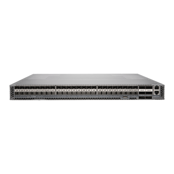
System Software on page 4 QFX5200-32C Hardware The QFX5200-32C is a compact 1 U standalone switch that provides a line rate configuration packet performance, very low latency, and a rich set of Layer 3 features. The routing engine and control plane are driven by the 1.8 Ghz quad-core Intel CPU with 16 GB of memory and two 32 GB solid-state drives (SSD) for storage. -
Page 22: System Software
Junos OS is installed on the redundant 32 GB solid state drives. The same Junos OS code base that runs on QFX5200 switches also runs on all Juniper Networks EX Series switches, and J Series, M Series, MX Series, and T Series routers. -
Page 23: Functionality
Do not connect feed A and feed B to the same power supply input terminal. Cooling system—The QFX5200 has five fan modules. If a fan module fails and is unable to keep the QFX5200 switch within the desired temperature thresholds, chassis alarms occur and the QFX5200 switch can shut down. - Page 24 QFX5200 Switch Hardware Guide Copyright © 2017, Juniper Networks, Inc.
-
Page 25: Chassis Components And Descriptions
Installing and Removing QFX5200 Hardware Components on page 99 QFX5200-32C Port Panel The port panel of the QFX5200-32C supports port configuration speeds of 100, 50, 40, 25, or 10 Gigabit Ethernet. The QFX5200-32C uses 28-Gbps quad small-form factor pluggable plus (QSFP28) sockets that are configured as 100 Gigabit Ethernet ports by default. -
Page 26: Switch Ports
QSFP+ to SFP+ DACBO cables (40 Gbps breaks out to 10 Gbps) Channelizing Interfaces For downstream traffic, the QFX5200-32C has 32 physical or 128 logical ports (32 x 4) that can be used for port channelization. The 100 Gigabit Ethernet ports can be channelized using breakout cables either to 2 independent downstream 50 Gigabit Ethernet or to 4 independent 25 Gigabit Ethernet ports. -
Page 27: Qfx5200 Field-Replaceable Units
QFX5200 Field-Replaceable Units Field-replaceable units (FRUs) are components that you can replace at your site. The QFX5200 device FRUs are hot-insertable and hot-removable: you can remove and replace one of them without powering off the switch or disrupting the switching function. -
Page 28: Qfx5200 Access Port And Uplink Port Leds
Installing and Removing QFX5200 Hardware Components on page 99 Documentation QFX5200 Access Port and Uplink Port LEDs The Link/Activity LED configuration for QFX5200 switches use bi-colored LEDs. The link LED indicates link activity or a fault. See Table 6 on page... -
Page 29: Qfx5200 Management Panel
Installing a Transceiver in a QFX Series Device Connecting a Fiber-Optic Cable to a QFX Series Device QFX5200 Management Panel The management panel of the QFX5200 switch is found on the Field Replaceable Unit (FRU) end of the switch as shown in Figure 3 on page 11. -
Page 30: Figure 4: Management Panel Components On Qfx5200
USB Port Specifications for the QFX Series on page 51 QFX5200 Cooling System and Airflow on page 17 QFX5200 AC Power Supply on page 23 Installing and Removing QFX5200 Hardware Components on page 99 Copyright © 2017, Juniper Networks, Inc. -
Page 31: Qfx5200 Management Port Leds
The management ports (labeled for 10/100/1000 Base-T and for 10/100/1000 Base-T and SFP 1000 Base-X connections) on a QFX5200 switch have two LEDs that indicate link status and link activity (see Figure 5 on page 13). The left LED indicates status;... -
Page 32: Qfx5200 Chassis Status Leds
QFX5200 Switch Hardware Guide QFX5200 Chassis Status LEDs The QFX5200 switch series has four status LEDs on the FRU side of the chassis, next to the management ports (see Figure 6 on page 14). Figure 6: Chassis Status LEDs on a QFX5200 Switch 1—... -
Page 33: Table 10: Chassis Status Leds On A Qfx5200 Switch
Chapter 2: Chassis Components and Descriptions Table 10: Chassis Status LEDs on a QFX5200 Switch Name Color State Description ALM–Alarm or beacon Unlit The switch is halted or there is no alarm. On steadily A major hardware fault has occurred, such as a temperature alarm or power failure, and the switch has halted. - Page 34 QFX5200 Switch Hardware Guide Copyright © 2017, Juniper Networks, Inc.
-
Page 35: Cooling System And Airflow
QFX5200 Fan Module LED on page 20 QFX5200 Cooling System and Airflow The cooling system in an QFX5200 device consists of five fan modules and a single fan in each power supply. The switch can be set up to work in one of two airflow directions: Airflow In–Air comes into the switch through the vents in the field-replaceable units... -
Page 36: Figure 7: Qfx5200 Fan Modules
Table 11 on page 18 lists the available fan module product SKUs and the direction of airflow in them: Table 11: Fan Modules in QFX5200 Switches Label on the Color of Fan Direction of Airflow in the Fan Module... -
Page 37: Switch
Chapter 3: Cooling System and Airflow Figure 8: Air In Airflow Through QFX5200 Figure 9: Air Out Airflow Through 1 U QFX5200 Switch Chassis Do Not Install Components with Different Airflow or Wattage in the Switch Do not mix power supplies with different airflow. If the power supplies are color-coded, ensure they are either all azure blue for airflow in models or all gold for airflow out models. -
Page 38: Qfx5200 Fan Module Led
CAUTION: Do not mix AC and DC power supplies in the same chassis. However if you need to convert a QFX5200 device to have a different airflow, you can change the airflow pattern. To convert an product SKU to an... -
Page 39: Table 12: Fan Tray Led In A Qfx5200 Switch
Related QFX5200 Cooling System and Airflow on page 17 Documentation Installing a Fan Module in a QFX5200 on page 81 Removing a Fan Module from a QFX5200 on page 82 Copyright © 2017, Juniper Networks, Inc. - Page 40 QFX5200 Switch Hardware Guide Copyright © 2017, Juniper Networks, Inc.
-
Page 41: Power Supply
Figure 11 on page 23 an example of a QFX5200 AC power supply. The AC power supply in QFX5200-32C switches is 850 W. Be sure to use the correct power supply for your chassis product SKU (see Table 13 on page 24). -
Page 42: Figure 12: Power Supply Handle Detail
Table 13 on page 24 shows the different power supplies and their direction of airflow. Table 13: Airflow Direction in QFX5200 AC Power Supplies Product Number Direction of Airflow... -
Page 43: Qfx5200 Dc Power Supply
(FRUs). You can install the power supplies without powering off the switch or disrupting the switching function. The DC power supply in QFX5200 is 850 W with dual feeds for power resiliency. Figure 13: DC Power Supply for QFX5200 Devices 1—... -
Page 44: Qfx5200 Ac Power Supply Leds
QFX5200 Switch Hardware Guide Figure 14: DC Power Supply Faceplate in QFX5200 Devices 1— Shunt negative input terminals (-48V) 5— ESD grounding point 2— Shunt positive input terminals (+RTN) 6— Fault LED 3— Terminal block 7— Output LED 4— Ejector lever 8—... -
Page 45: Qfx5200 Dc Power Supply Leds
Chapter 4: Power Supply Figure 15: AC Power Supply LEDs on a QFX5200 Switch AC OK DC OK Fault Table 14 on page 27 describes the LEDs on the AC power supplies. Table 14: AC Power Supply LEDs on a QFX5200 Switch... -
Page 46: Figure 16: Dc Power Supply Faceplate On A Qfx5200 Switch
QFX5200 Switch Hardware Guide Figure 16: DC Power Supply Faceplate on a QFX5200 Switch 1— Input LED 3— Fault LED 2—Output LED CAUTION: The V+ terminals are shunted internally together, as are the V- terminals. The same polarity terminal can be wired together from the same source to provide an additional current path in a higher power chassis. -
Page 47: Site Planning, Preparation, And Specifications
PART 2 Site Planning, Preparation, and Specifications Preparation Overview on page 31 Power Specifications and Requirements on page 39 Transceiver and Cable Specifications on page 43 Pinout Specifications on page 51 Copyright © 2017, Juniper Networks, Inc. - Page 48 QFX5200 Switch Hardware Guide Copyright © 2017, Juniper Networks, Inc.
-
Page 49: Preparation Overview
Site Electrical Wiring Guidelines on page 34 QFX5200 Rack Requirements on page 35 QFX5200 Cabinet Requirements on page 36 QFX5200 Clearance Requirements for Airflow and Hardware Maintenance on page 36 QFX5200 Site Preparation Checklist The checklist in Table 16 on page 31 summarizes the tasks you need to perform when preparing a site for a QFX5200 installation. -
Page 50: Qfx5200 Environmental Requirements And Specifications
General Site Guidelines on page 33 Installing and Connecting a QFX5200 on page 57 Mounting a QFX5200 in a Rack or Cabinet on page 59 QFX5200 Environmental Requirements and Specifications The switch must be installed in a rack or cabinet. It must be housed in a dry, clean, well-ventilated, and temperature-controlled environment. -
Page 51: General Site Guidelines
Articles 110-16, 110-17, and 110-18 of the National Electrical Code, ANSI/NFPA 70. Related QFX5200 Clearance Requirements for Airflow and Hardware Maintenance on page 36 Documentation Installing and Connecting a QFX5200 on page 57... -
Page 52: Site Electrical Wiring Guidelines
Electrical hazards as a result of power surges conducted over the lines into the equipment Related General Safety Guidelines and Warnings on page 127 Documentation General Electrical Safety Guidelines and Warnings on page 155 Prevention of Electrostatic Discharge Damage on page 156 Copyright © 2017, Juniper Networks, Inc. -
Page 53: Qfx5200 Rack Requirements
Secure the rack to the ceiling brackets as well as wall or floor brackets for maximum stability. Related QFX5200 Chassis Physical Specifications on page 7 Documentation Rack-Mounting and Cabinet-Mounting Warnings on page 138 QFX5200 Clearance Requirements for Airflow and Hardware Maintenance on page 36 Copyright © 2017, Juniper Networks, Inc. -
Page 54: Qfx5200 Cabinet Requirements
Mounting a QFX5200 in a Rack or Cabinet on page 59 QFX5200 Cabinet Requirements You can mount the QFX5200 in an enclosure or cabinet that contains a four-post 19-in. open rack as defined in Cabinets, Racks, Panels, and Associated Equipment (document number EIA-310-D) published by the Electronics Industry Association. -
Page 55: Figure 17: Clearance Requirements For Airflow And Hardware Maintenance For A
Leave at least 24 in. (61 cm) both in front of and behind the QFX5200. For service personnel to remove and install hardware components, you must leave adequate space at the front and back of the switch. - Page 56 QFX5200 Switch Hardware Guide Copyright © 2017, Juniper Networks, Inc.
-
Page 57: Power Specifications And Requirements
QFX5200 AC Power Specifications on page 39 AC Power Cord Specifications for a QFX Series Device on page 39 QFX5200 DC Power Specifications on page 41 QFX5200 Grounding Cable and Lug Specifications on page 41 QFX5200 AC Power Specifications Table 21 on page 39 describes the AC power specifications for a QFX5200. -
Page 58: Table 22: Ac Power Cord Specifications
AC Power Supply for a QFX3500, QFX3600, or QFX3600-I Device Documentation General Safety Guidelines and Warnings on page 127 General Electrical Safety Guidelines and Warnings on page 155 Prevention of Electrostatic Discharge Damage on page 156 AC Power Supply for a QFX5100 Device Copyright © 2017, Juniper Networks, Inc. -
Page 59: Qfx5200 Dc Power Specifications
(EMI) requirements. To ground a QFX5200, connect a grounding cable to earth ground and then attach it to the chassis grounding points. - Page 60 The grounding lug provided accommodates 14–10 AWG (2–5.3 mm²) stranded wire. The grounding cable that you provide for a QFX5200 must be 14 AWG (2 mm²), minimum 60° C wire, or as permitted by the local code.
-
Page 61: Transceiver And Cable Specifications
Calculating the Fiber-Optic Cable Power Margin for a QFX Series Device on page 48 Determining QFX5200 Optical Interface Support The QFX5200-32C has 32 quad small form-factor pluggable plus (QSFP+) ports for use as uplinks, downlinks, or as access ports. These 40-Gigabit Ethernet ports support QSFP+ transceivers, QSFP28 transceivers, QSFP+ direct-attach copper (DAC) cables, active optical cables (AOC) , and DAC breakout cables (DACBO). -
Page 62: Cable Specifications For Qsfp+ And Qsfp28 Transceivers
(JTAC) can help you diagnose the source of the problem. Your JTAC engineer might recommend that you check the third-party optic or cable and potentially replace it with an equivalent Juniper Networks optic or cable that is qualified for the device. -
Page 63: Transceiver And Cable Specifications
Table 24: QSFP+ MPO Cable Signals (continued) Fiber Signal Unused Unused Unused Rx3 (Receive) Rx2 (Receive) Rx1 (Receive) Rx0 (Receive) Table 25: QSFP+ MPO Fiber-Optic Crossover Cable Pinouts Related Determining QFX10000 Optical Transceiver and Cable Support Documentation Copyright © 2017, Juniper Networks, Inc. -
Page 64: Table 26: Cable Specifications For Console And Management Connections For The Qfx Series
Connecting a QFX3100 Director Device to a Network for Out-of-Band Management Connecting a QFX5100 Device to a Network for Out-of-Band Management Connecting a QFX5200 to a Network for Out-of-Band Management Understanding QFX Series Fiber-Optic Cable Signal Loss, Attenuation, and Dispersion To determine the power budget and power margin needed for fiber-optic connections, you need to understand how signal loss, attenuation, and dispersion affect transmission. -
Page 65: Signal Loss In Multimode And Single-Mode Fiber-Optic Cables
An efficient optical data link must have enough light to exceed the minimum power that the receiver requires to operate within its specifications. In addition, the total dispersion must be within the limits specified for the type of link in the Telcordia Technologies Copyright © 2017, Juniper Networks, Inc. -
Page 66: Calculating The Fiber-Optic Cable Power Budget For A Qfx Series Device
Calculate the link's power margin when planning fiber-optic cable layout and distances to ensure that fiber-optic connections have sufficient signal power to overcome system losses and still satisfy the minimum input requirements of the receiver for the required Copyright © 2017, Juniper Networks, Inc. -
Page 67: Table 27: Estimated Values For Factors Causing Link Loss
2 km: 2 km (1 dBm/km) = 2 dBm. Single-mode—0.5 dBm/km This example assumes the link is 2 km long. Fiber attenuation for 2 km: 2 km (0.5 dBm/km) = 1 dBm. Clock Recovery Module 1 dBm 1 dBm (CRM) Copyright © 2017, Juniper Networks, Inc. - Page 68 Also, the power margin value does not exceed the maximum receiver input power. Refer to the specifications for your receiver to find the maximum receiver input power. Related Understanding QFX Series Fiber-Optic Cable Signal Loss, Attenuation, and Dispersion Documentation on page 46 Copyright © 2017, Juniper Networks, Inc.
-
Page 69: Pinout Specifications
RJ-45 Management Port Connector Pinout Information on page 53 USB Port Specifications for the QFX Series The following Juniper Networks USB flash drives have been tested and are officially supported for the USB port in the QFX Series: RE-USB-1G-S—1-gigabyte (GB) USB flash drive (except QFX3100 Director device) RE-USB-2G-S—2-GB USB flash drive (except QFX3100 Director device) -
Page 70: Console Port Connector Pinouts For The Qfx Series
Transmit data Signal Ground Signal ground Signal Ground Signal ground RxD Input Receive data DCD Input Data carrier detect CTS Input Clear to send Related Connecting a QFX Series Device to a Management Console Documentation Copyright © 2017, Juniper Networks, Inc. -
Page 71: Rj-45 Management Port Connector Pinout Information
Chapter 8: Pinout Specifications RJ-45 Management Port Connector Pinout Information Table 29 on page 53 provides the pinout information for the RJ-45 connector for the management port on Juniper Networks devices. Table 29: RJ-45 Management Port Connector Pinout Information Signal Description... - Page 72 QFX5200 Switch Hardware Guide Copyright © 2017, Juniper Networks, Inc.
-
Page 73: Initial Installation And Configuration
Initial Installation and Configuration Unpacking and Mounting the Switch on page 57 Connecting the Switch to Power on page 63 Connecting the Switch to the Network on page 73 Performing Initial Configuration on page 77 Copyright © 2017, Juniper Networks, Inc. - Page 74 QFX5200 Switch Hardware Guide Copyright © 2017, Juniper Networks, Inc.
-
Page 75: Unpacking And Mounting The Switch
Unpacking and Mounting the Switch Installing and Connecting a QFX5200 on page 57 Unpacking a QFX5200 on page 58 Mounting a QFX5200 in a Rack or Cabinet on page 59 Installing and Connecting a QFX5200 You can mount a QFX5200: Flush with the front of a 19-in. -
Page 76: Unpacking A Qfx5200
QFX5200 Switch Hardware Guide Unpacking a QFX5200 The QFX5200 switch chassis is a rigid sheet-metal structure that houses the hardware components. A QFX5200 is shipped in a cardboard carton, secured with foam packing material. The carton also contains an accessory box and quick start instructions. -
Page 77: Mounting A Qfx5200 In A Rack Or Cabinet
Chapter 9: Unpacking and Mounting the Switch Mounting a QFX5200 in a Rack or Cabinet You can mount all QFX5200 switches on a four post 19-in. rack or cabinet using the mounting kit provided with the switch. For four post rack or cabinet installations, the mounting kit contains two front mounting rails with two matching rear mounting blades. -
Page 78: Four Post Procedure
If you are installing the QFX5200 switch above 60 in. (152.4 cm) from the floor, you can remove the power supplies and fan modules to minimize the weight before attempting to install the switch. -
Page 79: Figure 18: Attaching Mounting Rails To The Qfx5200-32C
Chapter 9: Unpacking and Mounting the Switch Figure 18: Attaching Mounting Rails to the QFX5200-32C Attach the mounting rail to the switch using the mounting screws. Tighten the screws. Repeats steps 3 and 4 on the opposite side of the switch. -
Page 80: Figure 20: Slide Mounting Blade Into Mounting Rail
Related Rack-Mounting and Cabinet-Mounting Warnings on page 138 Documentation Connecting AC Power to a QFX5200 on page 65 Connecting Earth Ground to a QFX5200 on page 64 Copyright © 2017, Juniper Networks, Inc. -
Page 81: Connecting The Switch To Power
CHAPTER 10 Connecting the Switch to Power Connecting Earth Ground to a QFX5200 on page 64 Connecting AC Power to a QFX5200 on page 65 Connecting DC Power to a QFX5200 on page 68 Copyright © 2017, Juniper Networks, Inc. -
Page 82: Connecting Earth Ground To A Qfx5200
(see Figure 21 on page 65). Before you connect earth ground to the protective earthing terminal of a QFX5200, ensure that a licensed electrician has attached an appropriate grounding lug to the grounding cable. -
Page 83: Connecting Ac Power To A Qfx5200
Connecting DC Power to a QFX5200 on page 68 Connecting AC Power to a QFX5200 The QFX5200 is shipped from the factory with two power supplies. Each power supply is a hot-removable and hot-insertable field-replaceable unit (FRU) when the second power supply is installed and running. - Page 84 23). Install the power supply in the chassis. For instructions on installing a power supply in a QFX5200, see “Installing a Power Supply in a QFX5200” on page NOTE: Each power supply must be connected to a dedicated power source outlet.
-
Page 85: Figure 22: Connecting An Ac Power Cord To An Ac Power Supply In A
If the amber fault LED is lit, remove power from the power supply, and replace the power supply (see “Removing a Fan Module from a QFX5200” on page 82). Do not remove the power supply until you have a replacement power supply ready: the power supplies or a blank cover panel must be installed in the switch to ensure proper airflow. -
Page 86: Connecting Dc Power To A Qfx5200
QFX5200 Switch Hardware Guide Connecting DC Power to a QFX5200 The QFX5200 is shipped from the factory with two power supplies. Each power supply is a hot-removable and hot-insertable field-replaceable unit (FRU) when the second power supply is installed and running. You can install replacement power supplies in the two slots next to the fan modules without powering off the switch or disrupting the switching function. - Page 87 Figure 23 on page 70 Figure 24 on page 71 The QFX5200 is designed to operate with a DC power supply that has a single, non-redundant, feed input. For source redundancy, two DC power supplies must be installed in QFX5200; connect source (A) to one power supply and connect source...
-
Page 88: Figure 23: Dc Power Supply Faceplate For A Qfx5200
Tighten the screws on the power supply terminals until snug using the screwdriver. Do not overtighten—apply between 5 in-lb (0.56 Nm) and 6 in-lb (0.68 Nm) of torque to the screws. Figure 23: DC Power Supply Faceplate for a QFX5200 1— Shunt negative input terminals (+RTN) 5—... -
Page 89: Figure 24: Securing Ring Lugs To The Terminals On The Qfx5200 Dc Power
Do not connect the terminals to different sources. Figure 24: Securing Ring Lugs to the Terminals on the QFX5200 DC Power Supply Replace the terminal block cover. - Page 90 QFX5200 Switch Hardware Guide Copyright © 2017, Juniper Networks, Inc.
-
Page 91: Connecting The Switch To The Network
Figure 26 on page 74): Connect one end of the Ethernet cable to the management port (labeled MGMT ) on the device. ETHERNET Connect the other end of the Ethernet cable to the management device. Copyright © 2017, Juniper Networks, Inc. -
Page 92: Connector
PC directly to the device, use a combination of the RJ-45 to DB-9 female adapter supplied with the device and a USB to DB-9 male adapter. You must provide the USB to DB-9 male adapter. Copyright © 2017, Juniper Networks, Inc. -
Page 93: Figure 28: Connecting A Device To A Management Console Through A Console
Figure 28: Connecting a Device to a Management Console Through a Console Server To Console port Console server Figure 29: Connecting a Device Directly to a Management Console Related Connecting a Device to a Network for Out-of-Band Management on page 73 Documentation Copyright © 2017, Juniper Networks, Inc. - Page 94 QFX5200 Switch Hardware Guide Copyright © 2017, Juniper Networks, Inc.
-
Page 95: Performing Initial Configuration
Performing Initial Configuration Configuring a QFX5200 on page 77 Configuring a QFX5200 You must perform the initial configuration of the QFX5200 through the console port using the command-line interface (CLI). Before you begin connecting and configuring a QFX5200, set the following parameter values on the console server or PC: Baud Rate—9600... - Page 96 Enable telnet service. [edit] root@# set system services telnet NOTE: When Telnet is enabled, you cannot log in to a QFX5200 switch through Telnet using root credentials. Root login is allowed only for SSH access. Enable SSH service for root login.
-
Page 97: Part 4 Installing, Maintaining, And Replacing Components
Replacing Cooling System Components on page 81 Replacing Power Supplies on page 85 Replacing Transceivers and Fiber-Optic Cables on page 89 Removing the Device on page 99 Contacting Customer Support and Returning the Chassis or Components on page 105 Copyright © 2017, Juniper Networks, Inc. - Page 98 QFX5200 Switch Hardware Guide Copyright © 2017, Juniper Networks, Inc.
-
Page 99: Replacing Cooling System Components
SKU you purchase. In legacy switches, or switches with an LCD, this airflow is called front to back and back to front. Before you install a fan module in a QFX5200, ensure that you have taken the necessary precautions to prevent electrostatic discharge (ESD) damage (see “Prevention of... -
Page 100: Removing A Fan Module From A Qfx5200
Before removing the fan module, ensure you have a replacement fan module at hand. Before you remove a fan module from a QFX5200, ensure that you have taken the necessary precautions to prevent electrostatic discharge (ESD) damage (see “Prevention... -
Page 101: Figure 31: Removing A Fan Module From A Qfx5200
Related QFX5200 Cooling System and Airflow on page 17 Documentation QFX5200 Field-Replaceable Units on page 9 QFX5200 Management Panel on page 11 Installing a Fan Module in a QFX5200 on page 81 Copyright © 2017, Juniper Networks, Inc. - Page 102 QFX5200 Switch Hardware Guide Copyright © 2017, Juniper Networks, Inc.
-
Page 103: Replacing Power Supplies
Before you install a power supply in a QFX5200, ensure that you have taken the necessary precautions to prevent electrostatic discharge (ESD) damage (see “Prevention of Electrostatic Discharge Damage”... -
Page 104: Removing A Power Supply From A Qfx5200
Before you remove a power supply from a QFX5200, ensure that you have taken the necessary precautions to prevent electrostatic discharge (ESD) damage (see “Prevention... - Page 105 Attach the ESD grounding strap to your bare wrist, and connect the strap to the ESD point on the chassis. NOTE: If only one power supply is installed in your QFX5200, you need to power off the switch before removing the power supply. See “Powering Off a QFX5200”...
-
Page 106: Figure 33: Removing A Power Supply From A Qfx5200
QFX5200 AC Power Supply on page 23 Documentation Connecting AC Power to a QFX5200 on page 65 Connecting DC Power to a QFX5200 on page 68 Installing a Power Supply in a QFX5200 on page 85 Copyright © 2017, Juniper Networks, Inc. -
Page 107: Replacing Transceivers And Fiber-Optic Cables
Connecting a Fiber-Optic Cable on page 95 Maintaining Fiber-Optic Cables on page 96 Removing a Transceiver The transceivers for Juniper Networks devices are hot-removable and hot-insertable field-replaceable units (FRUs): You can remove and replace them without powering off the device or disrupting device functions. - Page 108 Remove the cable connected to the transceiver (see “Disconnecting a Fiber-Optic Cable from a Device” on page 94). Cover the transceiver and the end of each fiber-optic cable connector with a rubber safety cap immediately after disconnecting the fiber-optic cables. Copyright © 2017, Juniper Networks, Inc.
-
Page 109: Figure 34: Removing An Sfp, Sfp+, Xfp, Or A Qsfp+ Transceiver
Place the transceiver in the antistatic bag or on the antistatic mat placed on a flat, stable surface. Place the dust cover over the empty port. Related Installing a Transceiver on page 92 Documentation Copyright © 2017, Juniper Networks, Inc. -
Page 110: Installing A Transceiver
(JTAC) can help you diagnose the source of the problem. Your JTAC engineer might recommend that you check the third-party optic or cable and potentially replace it with an equivalent Juniper Networks optic or cable that is qualified for the device. - Page 111 Remove the rubber safety cap when you are ready to connect the cable to the transceiver. WARNING: Do not look directly into a fiber-optic transceiver or into the ends of fiber-optic cables. Fiber-optic transceivers and fiber-optic cables connected to transceivers emit laser light that can damage your eyes. Copyright © 2017, Juniper Networks, Inc.
-
Page 112: Disconnecting A Fiber-Optic Cable From A Device
Connecting a Fiber-Optic Cable on page 95 Disconnecting a Fiber-Optic Cable from a Device Juniper Networks devices have field-replaceable unit (FRU) optical transceivers to which you can connect fiber-optic cables. Before you begin disconnecting a fiber-optic cable from an optical transceiver, ensure that you have taken the necessary precautions for safe handling of lasers. -
Page 113: Connecting A Fiber-Optic Cable
Secure the cables so that they do not support their own weight. Place excess cable out of the way in a neatly coiled loop. Placing fasteners on a loop helps cables maintain their shape. Copyright © 2017, Juniper Networks, Inc. -
Page 114: Maintaining Fiber-Optic Cables
Installing a Transceiver on page 92 Maintaining Fiber-Optic Cables on page 96 Maintaining Fiber-Optic Cables Fiber-optic cables connect to optical transceivers that are installed in Juniper Networks devices. To maintain fiber-optic cables: When you unplug a fiber-optic cable from a transceiver, place rubber safety caps over the transceiver and on the end of the cable. - Page 115 Chapter 15: Replacing Transceivers and Fiber-Optic Cables Related Connecting a Fiber-Optic Cable on page 95 Documentation Laser and LED Safety Guidelines and Warnings Copyright © 2017, Juniper Networks, Inc.
- Page 116 QFX5200 Switch Hardware Guide Copyright © 2017, Juniper Networks, Inc.
-
Page 117: Removing The Device
“Removing a Fan Module from a QFX5200” on page To install an SFP+, QSFP+, or QSF28 transceiver in a QFX5200, follow the instructions in Installing a Transceiver in a QFX Series Device. To remove an SFP+ , QSFP+, or QSFP28 transceiver from a QFX5200, follow the instructions in Removing a Transceiver from a QFX Series Device. -
Page 118: Powering Off A Qfx5200
QFX5200 Switch Hardware Guide To connect a fiber-optic cable to an SFP+, QSFP+, or QSFP28 transceiver in a QFX5200, follow the instructions in Connecting a Fiber-Optic Cable to a QFX Series Device. To disconnect a fiber-optic cable from an SFP+, QSFP+, or QSFP28 transceiver from a QFX5200, follow the instructions in Disconnecting a Fiber-Optic Cable from a QFX Series Device. - Page 119 ( ) port, see Connecting a QFX Series Device to a Management Console. You can shut down the QFX5200 from a management device on your out-of-band management network. For instructions about connecting a management device to the management ( ) port, see Connecting a QFX5200 to a Network for Out-of-Band Management.
-
Page 120: Removing A Qfx5200 From A Rack Or Cabinet
Connecting DC Power to a QFX5200 on page 68 Removing a QFX5200 from a Rack or Cabinet If you need to relocate an installed QFX5200, use the procedure described in this topic. (The remainder of this topic uses “rack” to mean “rack or cabinet.” ) - Page 121 Chapter 16: Removing the Device Ensure that the rack is stable and secured to the building. Ensure that there is enough space to place the removed QFX5200 in its new location and along the path to the new location. Read “General Safety Guidelines and Warnings”...
- Page 122 QFX5200 Switch Hardware Guide Copyright © 2017, Juniper Networks, Inc.
-
Page 123: Contacting Customer Support And Returning The Chassis Or
Packing an QFX5200 Device or Component for Shipping on page 110 Contacting Customer Support to Obtain Return Material Authorization If you are returning a device or hardware component to Juniper Networks for repair or replacement, obtain a Return Material Authorization (RMA) number from Juniper Networks Technical Assistance Center (JTAC). -
Page 124: Locating The Serial Number On A Qfx5200 Device Or Component
Locating the Serial Number on a QFX5200 Device or Component If you are returning a switch or component to Juniper Networks for repair or replacement, you must locate the serial number of the switch or component. You must provide the serial number to the Juniper Networks Technical Assistance Center (JTAC) when you contact them to obtain a Return Materials Authorization (RMA). -
Page 125: Locating The Chassis Serial Number Id Label On A Qfx5200
Locating the Chassis Serial Number ID Label on a QFX5200 The location for the chassis serial number ID label is located on the right side of the QFX5200-32C port panel. On legacy switches, or switches with an LCD, the port panel Copyright © 2017, Juniper Networks, Inc. -
Page 126: Locating The Serial Number Id Labels On Fru Components
Contacting Customer Support to Obtain a Return Materials Authorization for a QFX Series Device or Component If you are returning a QFX Series device or component to Juniper Networks for repair or replacement, you must first obtain a Return Materials Authorization (RMA) from the Juniper Networks Technical Assistance Center (JTAC). - Page 127 Chapter 17: Contacting Customer Support and Returning the Chassis or Components Locating the Serial Number on a QFX5200 Device or Component on page 106 Locating the Serial Number on a QFX10000 Switch or Component Locating the Serial Number on a QFX10002 or Component...
-
Page 128: Packing An Qfx5200 Device Or Component For Shipping
QFX5200 Switch Hardware Guide Packing an QFX5200 Device or Component for Shipping If you are returning a QFX5200 or component to Juniper Networks for repair or replacement, pack the item as described in this topic. Before you pack a QFX5200 or component: Ensure that you have taken the necessary precautions to prevent electrostatic discharge (ESD) damage. -
Page 129: Packing Qfx5200 Components For Shipping
Close the top of the cardboard shipping box and seal it with packing tape. Write the RMA number on the exterior of the box to ensure proper tracking. Related Returning a QFX5200 or Component for Repair or Replacement Documentation Copyright © 2017, Juniper Networks, Inc. - Page 130 QFX5200 Switch Hardware Guide Copyright © 2017, Juniper Networks, Inc.
-
Page 131: Troubleshooting
PART 5 Troubleshooting Restoring Junos OS on page 115 Alarm Messages on page 119 Copyright © 2017, Juniper Networks, Inc. - Page 132 QFX5200 Switch Hardware Guide Copyright © 2017, Juniper Networks, Inc.
-
Page 133: Restoring Junos Os
Junos OS release from http://www.juniper.net/customers/support/ NOTE: You can create the emergency boot device on another Juniper Networks switch or router, or any PC or laptop that supports Linux. The steps you take to create the emergency boot device vary, depending on the device. - Page 134 USB Port Specifications for the QFX Series on page 51 Documentation Performing a Recovery Installation Performing a QFabric System Recovery Installation on the Director Group Performing a Recovery Installation Using an Emergency Boot Device on page 117 Copyright © 2017, Juniper Networks, Inc.
-
Page 135: Performing A Recovery Installation Using An Emergency Boot Device
Networks Junos OS, the active configuration, and the rescue configuration—and copies all of these files into a memory source. See Creating a Snapshot and Using It to Boot a Device. NOTE: System snapshot is not supported on the QFX10000 and QFX5200 switches. WARNING: The recovery installation process completely overwrites the entire contents of the internal flash storage. - Page 136 QFX5200 Switch Hardware Guide Junos Snapshot Installer - (c) Juniper Networks 2013 Reboot Install Junos Snapshot [14.1X53-D11_vjunos.61] Boot to host shell [debug] Select install the snapshot. Install Junos Snapshot The software prompts you with the following option if you have Junos OS software from the factory installed on the emergency boot device.
-
Page 137: Alarm Messages
Alarm Messages Understanding Alarms on page 119 Interface Alarm Messages on page 120 Chassis Alarm Messages on QFX5100, QFX5110, and QFX5200 Switches on page 121 Understanding Alarms The QFX Series and OCX Series support different alarm types and severity levels. -
Page 138: Interface Alarm Messages
[ ] hierarchy level. alarm edit chassis NOTE: If you configure a yellow alarm on the QFX3008-I Interconnect device, it will be handled as a red alarm. Copyright © 2017, Juniper Networks, Inc. -
Page 139: Chassis Alarm Messages On Qfx5100, Qfx5110, And Qfx5200 Switches
Chassis alarms indicate a failure on the device or one of its components. Chassis alarms are preset and cannot be modified. Chassis alarms on QFX5100, QFX5110, and QFX5200 devices have two severity levels: Major (red)—Indicates a critical situation on the device that has resulted from one of... - Page 140 Reboot the switch with only AC or only DC power supplies. Replace the removed power supply or PEM pem-number Removed reboot the switch. The switch can continue to operate with a single power supply. Copyright © 2017, Juniper Networks, Inc.
- Page 141 Configuration. Install the required license for the feature Feature usage requires a license specified in the alarm. For more information, see Software Features That Require Licenses on the QFX Series. License for feature expired Copyright © 2017, Juniper Networks, Inc.
- Page 142 Related Chassis Status LEDs on a QFX5100 Device Documentation QFX5110 Chassis Status LEDs QFX5200 Chassis Status LEDs on page 14 Configuring the Junos OS to Determine Conditions That Trigger Alarms on Different Interface Types alarm Copyright © 2017, Juniper Networks, Inc.
-
Page 143: Part 6 Safety And Compliance Information
Radiation and Laser Safety Guidelines and Warnings on page 145 Maintenance and Operational Safety Warnings on page 149 Electrical Safety Guidelines and Warnings on page 155 Agency Approvals and Compliance Statements on page 171 Copyright © 2017, Juniper Networks, Inc. - Page 144 QFX5200 Switch Hardware Guide Copyright © 2017, Juniper Networks, Inc.
-
Page 145: General Safety Guidelines And Warnings
Operate the device only when it is properly grounded. Ensure that the separate protective earthing terminal provided on this device is permanently connected to earth. Replace fuses only with fuses of the same type and rating. Copyright © 2017, Juniper Networks, Inc. -
Page 146: Definitions Of Safety Warning Levels
This symbol means danger. You are in a situation that could cause bodily injury. Before you work on any equipment, be aware of the hazards involved with electrical circuitry and be familiar with standard practices for preventing accidents. Copyright © 2017, Juniper Networks, Inc. - Page 147 Varning! Denna varningssymbol signalerar fara. Du befinner dig i en situation som kan leda till personskada. Innan du utför arbete på någon utrustning måste du vara medveten om farorna med elkretsar och känna till vanligt förfarande för att förebygga skador. Copyright © 2017, Juniper Networks, Inc.
-
Page 148: Qualified Personnel Warning
General Safety Guidelines and Warnings on page 127 Documentation General Electrical Safety Guidelines and Warnings on page 155 AC Power Electrical Safety Guidelines on page 158 DC Power Electrical Safety Guidelines for Switches on page 160 Copyright © 2017, Juniper Networks, Inc. -
Page 149: Warning Statement For Norway And Sweden
The equipment must be connected to an earthed mains socket-outlet. Advarsel Apparatet skal kobles til en jordet stikkontakt. Varning! Apparaten skall anslutas till jordat nätuttag. Related General Safety Guidelines and Warnings on page 127 Documentation Copyright © 2017, Juniper Networks, Inc. - Page 150 QFX5200 Switch Hardware Guide Copyright © 2017, Juniper Networks, Inc.
-
Page 151: Fire Safety Requirements
In addition, you should establish procedures to protect your equipment in the event of a fire emergency. Juniper Networks products should be installed in an environment suitable for electronic equipment. We recommend that fire suppression equipment be available in the event of a fire in the vicinity of the equipment and that all local fire, safety, and electrical codes and ordinances be observed when you install and operate your equipment. - Page 152 To keep warranties effective, do not use a dry chemical fire extinguisher to control a fire at or near a Juniper Networks device. If a dry chemical fire extinguisher is used, the unit is no longer eligible for coverage under a service agreement.
-
Page 153: Installation Safety Guidelines And Warnings
CHAPTER 22 Installation Safety Guidelines and Warnings Installation Instructions Warning on page 135 Chassis Lifting Guidelines for a QFX5200 Device on page 136 Restricted Access Warning on page 136 Ramp Warning on page 138 Rack-Mounting and Cabinet-Mounting Warnings on page 138... -
Page 154: Chassis Lifting Guidelines For A Qfx5200 Device
Laser and LED Safety Guidelines and Warnings Grounded Equipment Warning on page 142 Chassis Lifting Guidelines for a QFX5200 Device The weight of a fully -loaded QFX5200 switch chassis is approximately 23.5 lb (10.66 kg). Observe the following guidelines for lifting and moving a QFX5200: CAUTION: If you are installing the QFX5200 above 60 in. - Page 155 Varning! Denna enhet är avsedd för installation i områden med begränsat tillträde. Ett område med begränsat tillträde får endast tillträdas av servicepersonal med ett speciellt verktyg, lås och nyckel, eller annan säkerhetsanordning, och kontrolleras av den auktoritet som ansvarar för området. Copyright © 2017, Juniper Networks, Inc.
-
Page 156: Ramp Warning
Uneven mechanical loading could lead to a hazardous condition. WARNING: To prevent bodily injury when mounting or servicing the device in a rack, take the following precautions to ensure that the system remains stable. The following directives help maintain your safety: Copyright © 2017, Juniper Networks, Inc. - Page 157 De onderstaande richtlijnen worden verstrekt om uw veiligheid te verzekeren: De Juniper Networks switch moet in een stellage worden geïnstalleerd die aan een bouwsel is verankerd. Dit toestel dient onderaan in het rek gemonteerd te worden als het toestel het enige in het rek is.
- Page 158 QFX5200 Switch Hardware Guide Le rack sur lequel est monté le Juniper Networks switch doit être fixé à la structure du bâtiment. Si cette unité constitue la seule unité montée en casier, elle doit être placée dans le bas. Si cette unité est montée dans un casier partiellement rempli, charger le casier de bas en haut en plaçant l'élément le plus lourd dans le bas.
- Page 159 Chapter 22: Installation Safety Guidelines and Warnings Juniper Networks switch må installeres i et stativ som er forankret til bygningsstrukturen. Denne enheten bør monteres nederst i kabinettet hvis dette er den eneste enheten i kabinettet. Ved montering av denne enheten i et kabinett som er delvis fylt, skal kabinettet lastes fra bunnen og opp med den tyngste komponenten nederst i kabinettet.
-
Page 160: Grounded Equipment Warning
Följande riktlinjer ges för att trygga din säkerhet: Juniper Networks switch måste installeras i en ställning som är förankrad i byggnadens struktur. Om denna enhet är den enda enheten på ställningen skall den installeras längst ned på... - Page 161 Varning! Denna utrustning är avsedd att jordas. Se till att värdenheten är jordad vid normal användning. Related General Safety Guidelines and Warnings on page 127 Documentation AC Power Electrical Safety Guidelines on page 158 DC Power Electrical Safety Guidelines for Switches on page 160 Copyright © 2017, Juniper Networks, Inc.
- Page 162 QFX5200 Switch Hardware Guide Copyright © 2017, Juniper Networks, Inc.
-
Page 163: Radiation And Laser Safety Guidelines And Warnings
åpning når det ikke er tilkoblet en fiberkabel. Aviso Dada a possibilidade de emissão de radiação invisível através do orifício da via de acesso, quando esta não tiver nenhum cabo de fibra conectado, Copyright © 2017, Juniper Networks, Inc. -
Page 164: Laser And Led Safety Guidelines And Warnings For The Qfx Series
Unterminated Fiber-Optic Cable Warning on page 147 Class 1M Laser Product Warning WARNING: Class 1M laser product. Waarschuwing Laserproducten van Klasse 1M (IEC). Varoitus Luokan 1M (IEC) lasertuotteita. Attention Produits laser catégorie 1M (IEC). Warnung Laserprodukte der Klasse 1M (IEC). Copyright © 2017, Juniper Networks, Inc. -
Page 165: Class 1M Laser Radiation Warning
Laserstrahl schauen oder diesen mit einem optischen Instrument direkt ansehen. Ein Betrachten des Laserstrahls mit bestimmten optischen Instrumenten, wie z.B. Augenlupen, Vergrößerungsgläsern und Mikroskopen innerhalb eines Abstands von 100 mm kann für das Auge gefährlich sein. Copyright © 2017, Juniper Networks, Inc. - Page 166 (t.ex. lupper, förstoringsglas och mikroskop) från ett avstånd på 100 mm kan skada ögonen. Related General Safety Guidelines and Warnings on page 127 Documentation Radiation from Open Port Apertures Warning on page 145 Installation Instructions Warning on page 135 Grounded Equipment Warning on page 142 Copyright © 2017, Juniper Networks, Inc.
-
Page 167: Maintenance And Operational Safety Warnings
Attention Danger d'explosion si la pile n'est pas remplacée correctement. Ne la remplacer que par une pile de type semblable ou équivalent, recommandée par le fabricant. Jeter les piles usagées conformément aux instructions du fabricant. Copyright © 2017, Juniper Networks, Inc. -
Page 168: Jewelry Removal Warning
Metalliesineet kuumenevat, kun ne ovat yhteydessä sähkövirran ja maan kanssa, ja ne voivat aiheuttaa vakavia palovammoja tai hitsata metalliesineet kiinni liitäntänapoihin. Attention Avant d'accéder à cet équipement connecté aux lignes électriques, ôter tout bijou (anneaux, colliers et montres compris). Lorsqu'ils sont branchés Copyright © 2017, Juniper Networks, Inc. -
Page 169: Lightning Activity Warning
Waarschuwing Tijdens onweer dat gepaard gaat met bliksem, dient u niet aan het systeem te werken of kabels aan te sluiten of te ontkoppelen. Varoitus Älä työskentele järjestelmän parissa äläkä yhdistä tai irrota kaapeleita ukkosilmalla. Copyright © 2017, Juniper Networks, Inc. -
Page 170: Operating Temperature Warning
6 in. (15.2 cm) of clearance around the ventilation openings. Waarschuwing Om te voorkomen dat welke switch van de Juniper Networks router dan ook oververhit raakt, dient u deze niet te bedienen op een plaats waar de maximale aanbevolen omgevingstemperatuur van 40°... -
Page 171: Product Disposal Warning
15,2 cm à volta das aberturas de ventilação. ¡Atención! Para impedir que un encaminador de la serie Juniper Networks switch se recaliente, no lo haga funcionar en un área en la que se supere la temperatura ambiente máxima recomendada de 40°... - Page 172 AC Power Electrical Safety Guidelines on page 158 DC Power Electrical Safety Guidelines for Switches on page 160 Laser and LED Safety Guidelines and Warnings Installation Instructions Warning on page 135 Grounded Equipment Warning on page 142 Copyright © 2017, Juniper Networks, Inc.
-
Page 173: Electrical Safety Guidelines And Warnings
(ESD) grounding strap to an ESD point and place the other end of the strap around your bare wrist. Failure to use an ESD grounding strap could result in damage to the device. Copyright © 2017, Juniper Networks, Inc. -
Page 174: Prevention Of Electrostatic Discharge Damage
Observe the following guidelines to minimize the potential for electrostatic discharge (ESD) damage, which can cause intermittent or complete component failures: Copyright © 2017, Juniper Networks, Inc. -
Page 175: Figure 38: Placing A Component Into An Antistatic Bag
To dissipate this charge, always ground the cables to a suitable and safe earth ground before connecting them to the system. Related General Safety Guidelines and Warnings on page 127 Documentation Copyright © 2017, Juniper Networks, Inc. -
Page 176: Action To Take After An Electrical Accident
The socket outlet must be near the AC-powered device and be easily accessible. For devices that have more than one power supply connection, you must ensure that all power connections are fully disconnected so that power to the device is completely Copyright © 2017, Juniper Networks, Inc. -
Page 177: Ac Power Disconnection Warning
Aviso Antes de trabalhar num chassis, ou antes de trabalhar perto de unidades de fornecimento de energia, desligue o cabo de alimentação nas unidades de corrente alternada. Copyright © 2017, Juniper Networks, Inc. -
Page 178: Dc Power Electrical Safety Guidelines For Switches
This topic applies to hardware devices in the EX Series product family, which includes EX Series switches and the XRE200 External Routing Engine. This topic also applies to hardware devices in the QFX Series and to OCX1100 switches. Copyright © 2017, Juniper Networks, Inc. - Page 179 For personal safety, connect the green and yellow wire to safety (earth) ground at both the device and the supply side of the DC wiring. Copyright © 2017, Juniper Networks, Inc.
- Page 180 Connecting DC Power to an XRE200 External Routing Engine Connecting DC Power to a QFX3500, QFX3600, or QFX3600-I Device Connecting DC Power to a QFX5100 Device Connecting DC Power to a QFX5200 on page 68 Connecting DC Power to a QFX10002 Connecting DC Power to a QFX10000...
-
Page 181: Dc Power Disconnection Warning
Aviso Antes de executar um dos seguintes procedimentos, certifique-se que desligou a fonte de alimentação de energia do circuito de corrente contínua. Para se assegurar que toda a corrente foi DESLIGADA, localize o disjuntor no Copyright © 2017, Juniper Networks, Inc. -
Page 182: Dc Power Grounding Requirements And Warning
Varoitus Laitetta asennettaessa on maahan yhdistäminen aina tehtävä ensiksi ja maadoituksen irti kytkeminen viimeiseksi. Attention Lors de l'installation de l'appareil, la mise à la terre doit toujours être connectée en premier et déconnectée en dernier. Copyright © 2017, Juniper Networks, Inc. -
Page 183: Dc Power Wiring Sequence Warning
à l'extrémité de câblage. En reliant la puissance, l'ordre approprié de câblage est rectifié pour rectifier, +RTN à +RTN, puis –48 V à –48 V. En débranchant la puissance, l'ordre approprié de câblage est –48 V Copyright © 2017, Juniper Networks, Inc. - Page 184 General Safety Guidelines and Warnings on page 127 Documentation General Electrical Safety Guidelines and Warnings on page 155 DC Power Electrical Safety Guidelines for Switches on page 160 DC Power Disconnection Warning on page 163 Copyright © 2017, Juniper Networks, Inc.
-
Page 185: Dc Power Wiring Terminations Warning
Estas terminações de cabo deverão ser do tamanho apropriado para os Copyright © 2017, Juniper Networks, Inc. -
Page 186: Multiple Power Supplies Disconnection Warning
DC Power Electrical Safety Guidelines for Switches on page 160 TN Power Warning WARNING: The device is designed to work with a TN power system. Waarschuwing Het apparaat is ontworpen om te functioneren met TN energiesystemen. Copyright © 2017, Juniper Networks, Inc. - Page 187 TN-typ. Related General Safety Guidelines and Warnings on page 127 Documentation General Electrical Safety Guidelines and Warnings on page 155 Grounded Equipment Warning on page 142 Multiple Power Supplies Disconnection Warning on page 168 Copyright © 2017, Juniper Networks, Inc.
- Page 188 QFX5200 Switch Hardware Guide Copyright © 2017, Juniper Networks, Inc.
-
Page 189: Chapter 26 Agency Approvals And Compliance Statements
Industry Canada ICES 003, Class A VCCI Regulations for Voluntary Control Measures of Radio Interference Generated by Information Technology Equipment, (Class A). EN 300 386, Class A EN 61000-3-2 Power Line Harmonics EN 61000-3-3 Voltage Fluctuations and Flicker Copyright © 2017, Juniper Networks, Inc. -
Page 190: Compliance Statements For Emc Requirements For The Qfx Series
CAUTION: Users should not attempt to make electrical ground connections by themselves, but should contact the appropriate inspection authority or an electrician, as appropriate. Copyright © 2017, Juniper Networks, Inc. -
Page 191: European Community
The preceding translates as follows: This equipment is Industrial (Class A) electromagnetic wave suitability equipment and seller or user should take notice of it, and this equipment is to be used in the places except for home. Copyright © 2017, Juniper Networks, Inc. -
Page 192: United States
The battery return connection is to be treated as an Isolated DC return (DC-I), as defined in GR-1089-CORE. GR-63-CORE: NEBS, Physical Protection The equipment is suitable for installation as part of the Common Bonding Network (CBN). The equipment is suitable for installation in a central office (CO). Copyright © 2017, Juniper Networks, Inc. - Page 193 Chapter 26: Agency Approvals and Compliance Statements Related Agency Approvals for the QFX Series on page 171 Documentation Copyright © 2017, Juniper Networks, Inc.
- Page 194 QFX5200 Switch Hardware Guide Copyright © 2017, Juniper Networks, Inc.
Need help?
Do you have a question about the QFX5200 and is the answer not in the manual?
Questions and answers