Juniper QFX5120 Series Quick Start Manual
Hide thumbs
Also See for QFX5120 Series:
- Hardware manual (321 pages) ,
- Quick start manual (20 pages) ,
- Manual (15 pages)
Table of Contents
Advertisement
Quick Start Guide
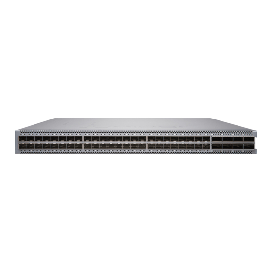
QFX5120 Switch Quick Start
IN THIS GUIDE
System Overview | 1
System Overview
The QFX5120 switches deliver low latency, rich Layer 2 and Layer 3 features, and advanced EVPN-VXLAN capabilities.
These switches can be used as data center top-of-rack and as aggregation switches for enterprise multicloud deployments.
These switches are also designed for extremely agile data centers that demand support for overlay and underlay network
architectures.
Two variants of the QFX5120 switches are available-32-port and 48-port switches, with AC or DC power supplies, and
with different airflow directions. Offering native 25-Gigabit Ethernet with 100-Gigabit Ethernet uplink ports on the
QFX5120-48Y, combined with 32 ports of 100-Gigabit Ethernet on the QFX5120-32C, the QFX5120 switches are ideally
suited for spine-and-leaf network deployments. The QFX5120 switches run standard Junos operating system (OS).
QFX5120-48Y switches also support virtual chassis technology. You can interconnect up to two QFX5120-48Y switches
in a QFX5120-48Y virtual chassis.
Advertisement
Table of Contents

Subscribe to Our Youtube Channel
Related Manuals for Juniper QFX5120 Series


Summary of Contents for Juniper QFX5120 Series
-
Page 1: Table Of Contents
Part 4: Connect Power to the Switch | 10 Part 5: Perform Initial Configuration | 13 Safety Warnings Summary | 15 Contacting Juniper Networks | 16 System Overview The QFX5120 switches deliver low latency, rich Layer 2 and Layer 3 features, and advanced EVPN-VXLAN capabilities. -
Page 2: Tools And Parts Required For Installation
The QFX5120-32C switch is available in four models, with AC or DC power supplies, and with front-to-back or back-to-front airflow. NOTE: See the complete documentation at https://www.juniper.net/documentation/product/en_US/qfx5120. Tools and Parts Required for Installation To mount a QFX5120 switch on a rack, you need: Two front-mounting brackets and twelve screws to secure the brackets to the chassis—provided... - Page 3 Register product serial numbers on the Juniper Networks website and update the installation base data if there is any addition or change to the installation base or if the installation base is moved. Juniper Networks will not be held accountable for not meeting the hardware replacement service-level agreement for products that do not have registered serial numbers or accurate installation base data.
-
Page 4: Part 1: Install A Power Supply
NOTE: Power supplies and fan modules must have the same airflow direction. The airflow direction on the power supplies must match the respective airflow direction on the fan modules. Part 1: Install a Power Supply NOTE: Each power supply must be connected to a dedicated power source outlet. The power supply slots are on the rear panel. -
Page 5: Part 2: Install A Fan Module
Figure 2: Installing a DC Power Supply in the QFX5120–32C Switch Figure 3: Installing an AC Power Supply in the QFX5120-48Y Switch Figure 4: Installing a DC Power Supply in the QFX5120-48Y Switch Part 2: Install a Fan Module NOTE: The fan module slots are located on the rear panel of the switch. - Page 6 Figure 5: Installing a Fan Module in the QFX5120-32C Switch Figure 6: Installing a Fan Module in the QFX5120-48Y Switch 1. Remove the fan module from its bag. 2. Hold the handle of the fan module with one hand, and support the weight of the module with the other hand. Place the fan module in the fan module slot on the rear panel of the switch and slide it in until it is fully seated.
-
Page 7: Part 3: Mount The Switch On Four Posts Of A Rack
Part 3: Mount the Switch on Four Posts of a Rack You can mount a QFX5120 switch on four posts of a 19-in. rack. This guide describes the procedure to mount the switch on a 19-in. rack. Mounting a QFX5120 switch requires one person to lift the switch and a second person to install the mounting screws to secure the switch to the rack. - Page 8 Figure 8: Aligning the Holes for Mounting Rail and Attaching with Screws to the QFX5120-32C Chassis 5. Position the mounting brackets along the side panels of the chassis, aligning them with the front panel. Figure 9: Attaching Front-Mounting Brackets to the QFX5120-48Y Chassis 6.
- Page 9 7. Have the second person secure the switch to the rack by inserting the screws appropriate for the rack through the bracket and the threaded holes on the rack. Tighten the screws. 8. On the rear of the switch chassis, slide the rear-mounting brackets into the front-mounting brackets on either side of the chassis until the rear-mounting brackets contact the rack rails (see Figure 12 Figure...
-
Page 10: Part 4: Connect Power To The Switch
Part 4: Connect Power to the Switch Depending on the model of your switch, you can use either AC or DC power supplies. The power supplies are installed in the slots on the rear panel. Before you connect power to the switch, wrap and fasten one end of an ESD wrist strap around your bare wrist, and connect the other end of the strap to the ESD point on the switch. - Page 11 Figure 16: Connecting Power to an AC-Powered QFX5120-48Y Switch Retainer tab loop — To connect power to a DC-powered QFX5120-32C switch: 1. Attach the grounding strap to your bare wrist and to a site ESD point. 2. Ensure that the input circuit breaker is open so that the voltage across the DC power source cable leads is 0 V and that the cable leads do not become active while you are connecting DC power.
- Page 12 CAUTION: The connection between each power source and power supply must include a circuit breaker. Do not connect two sources to a single power supply because doing so can potentially cause circulating current in feed wires whenever there is any difference in the voltage of the two sources.
-
Page 13: Part 5: Perform Initial Configuration
5. Close the input circuit breaker. 6. Verify that the IN OK and the OUT OK LEDs on the power supply are lit green and are on steadily. See Figure Figure 18: Connecting Power to a DC-Powered QFX5120-48Y Switch Part 5: Perform Initial Configuration You must perform the initial configuration for QFX5120 switch by using the console port. - Page 14 root> configure 6. Add a password to the root administration user account. [edit] root@# set system root-authentication plain-text-password New password:password Retype new password:password 7. (Optional) Configure the name of the switch. If the name includes spaces, enclose the name in quotation marks (“ ”). [edit] root@# set system host-name host-name 8.
-
Page 15: Safety Warnings Summary
17. Enter yes to commit the configuration. The configuration is committed as the active configuration for the switch. You can now log in by using the CLI and continue configuring the switch. Safety Warnings Summary This is a summary of safety warnings. For a complete list of warnings, including translations, see the QFX5120 documentation at https://www.juniper.net/documentation/product/en_US/qfx5120. -
Page 16: Contacting Juniper Networks
Metal objects heat up when connected to power and ground and can cause serious burns or become welded to the terminals. Power Cable Warning (Japanese) The attached power cable is only for this product. Do not use this cable for another product. Contacting Juniper Networks For technical support, see http://www.juniper.net/support/requesting-support.html. - Page 17 Juniper Networks, the Juniper Networks logo, Juniper, and Junos are registered trademarks of Juniper Networks, Inc. in the United States and other countries. All other trademarks, service marks, registered marks, or registered service marks are the property of their respective owners. Juniper Networks assumes no responsibility for any inaccuracies in this document. Juniper Networks reserves the right to change, modify, transfer, or otherwise revise this publication without notice.
Need help?
Do you have a question about the QFX5120 Series and is the answer not in the manual?
Questions and answers