Table of Contents
Advertisement
Quick Links
Advertisement
Table of Contents
Troubleshooting

Related Manuals for Juniper QFX5240


Summary of Contents for Juniper QFX5240
- Page 1 QFX5240 Switch Hardware Guide Published 2024-05-03...
- Page 2 The Juniper Networks product that is the subject of this technical documentation consists of (or is intended for use with) Juniper Networks software. Use of such software is subject to the terms and conditions of the End User License Agreement ("EULA") posted at https:/ /support.juniper.net/support/eula/.
-
Page 3: Table Of Contents
Table of Contents About this Guide | vii Fast Track: Initial Installation Fast Track to Rack Installation and Power | 2 Install the QFX5240 Switch in a Rack | 2 Connect to Power | 8 Overview QFX5240 System Overview | 12... - Page 4 QFX5240 Environmental Requirements and Specifications | 40 General Site Guidelines | 41 QFX5240 Grounding Cable and Lug Specifications | 41 QFX5240 Clearance Requirements for Airflow and Hardware Maintenance | 42 Site Electrical Wiring Guidelines | 43 QFX5240 Rack Requirements | 44...
- Page 5 Mount the QFX5240 Switch in a Four-Post Rack by Using the QFX5240-2U-4PRMK Rack Mount Kit | 72 Before You Begin Rack Mounting | 73 Mount the QFX5240 in a Four-Post Rack | 74 Connect the QFX5240 Switch to Power | 79...
- Page 6 List the Chassis and Component Details Using the CLI | 120 Locate the Chassis Serial Number ID Label on a QFX5240 Switch | 121 Locate the Serial Number ID Labels on FRUs in a QFX5240 Switch | 122 Remove the Solid-State Drives for RMA on QFX5240 Switches | 123 How to Return a Hardware Component to Juniper Networks, Inc.
-
Page 7: About This Guide
About this Guide Use this guide to plan, install, perform initial software configuration, perform routine maintenance, and to troubleshoot QFX5240 switches. After completing the installation and basic configuration procedures covered in this guide, refer to the Junos OS documentation for further software configuration. -
Page 8: Fast Track: Initial Installation
C HAPTER Fast Track: Initial Installation Fast Track to Rack Installation and Power | 2... -
Page 9: Fast Track To Rack Installation And Power
Fast Track to Rack Installation and Power IN THIS SECTION SUMMARY Install the QFX5240 Switch in a Rack | 2 This procedure walks you through the most basic steps for installing your QFX5240 switch in a rack Connect to Power | 8 and connecting it to power. - Page 10 1. Outer rail 2. Slider rail 3. Inner rail bracket Remove the Inner Rail Bracket from the Slide Rail Assembly 1. Wrap and fasten one end of the ESD grounding strap around your bare wrist, and connect the other end to a site ESD point. 2.
-
Page 11: Install The Slide Rail Assembly In The Rack
a. Slider rail b. Outer rail Install the Slide Rail Assembly in the Rack 1. Move the latch on the rear-end of the slide rail assembly to the open position. 2. Align the rear end of slide rail assembly with the rear rack-post holes that you want to use. The mounting pegs on the outer rail enter the rear rack-post holes from the inside of the rack post. - Page 12 5. Adjust the slider rail length and push the front mounting pegs on it into the front rack-post holes. You will hear a click sound.
-
Page 13: Mount The Switch In The Rack
6. The slide rail assembly is fully installed. Check if both the slide rail assemblies are at the same height with each other and are level front-to-back. Mount the Switch in the Rack 1. Pull the slider rails out to their full extended lock position, and ensure that the ball bearing retainer is located at the front of the slider rail. - Page 14 2. Lift the switch and align the rear of the inner rail brackets with the front ends of the slider rails on the rack. 3. Push the inner rail brackets into the slider rails until you hit a stop. After you hit a stop, pull/push the blue release tab on the inner rail brackets.
-
Page 15: Connect To Power
Ground the QFX5240 Switch | 8 Connect the Power Cord and Power On the Switch | 9 This topic describes the steps to connect an AC-powered QFX5240 to power. To connect QFX5240 to power, complete the following procedures: Ground the QFX5240 Switch To ground the QFX5240 switch, do the following: 1. - Page 16 4. Secure the grounding lug to the protective earthing terminal with the M6 screws and star washers. Figure 1: Attach the Grounding Cable to the QFX5240 5. Dress the grounding cable and ensure that it does not touch or block access to other device components.
- Page 17 4. Insert the power cord coupler in the power socket of the switch. 5. If the AC power source outlet has a power switch, turn it on. The QFX5240 doesn't have a power switch. The switch powers on as soon as you plug it in.
-
Page 18: Overview
C HAPTER Overview QFX5240 System Overview | 12 QFX5240 Port Panel | 17 QFX5240 Management Panel | 21 QFX5240 Power System | 28 QFX5240 Cooling System | 32... -
Page 19: Qfx5240 System Overview
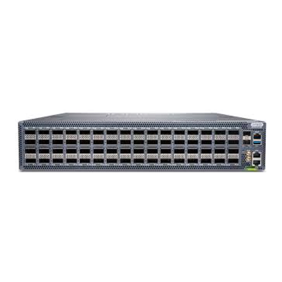
(QSFP-DD) ports and 2 10-Gbps SFP+ ports. With a bandwidth of 51.2 terabits per second (Tbps), the QFX5240 is an optimal choice for shallow buffer platforms for the spine role in the data center fabric. The QFX5240 switches use the high-radix class TH5 - BCM78900 chip, which is a dedicated ASIC for high-bandwidth network switching devices. - Page 20 Figure 2: Front View of the QFX5240-64OD Switch Figure 3: Rear View of the QFX5240-64OD Switch Figure 4: Front View of the QFX5240-64QD Switch...
-
Page 21: Qfx5240 Hardware Models
Figure 5: Rear View of the QFX5240-64QD Switch QFX5240 Hardware Models The QFX5240 has two models: QFX5240-64OD-AO and QFX5240-64QD-AO. Table 1 on page 14 provides an overview of the QFX5240 hardware models. Table 1: QFX5240 Hardware Models Model Description Airflow... -
Page 22: System Software
AC input line frequency 50/60 Hz • QFX5240 cooling system—The cooling system consists of four front-to-back (airflow out or AFO) fan modules with each fan module containing 2 rotors. The cooling system offers N+1 redundancy at rotor level. The fan modules are hot-insertable and hot-removable FRUs. -
Page 23: Qfx5240 Field-Replaceable Units
AIR OUT, port-to-FRU airflow Front-to-back QFX5240 Field-Replaceable Units Field-replaceable units (FRUs) are switch components that you can replace at your site. The QFX5240 switches uses these types of FRUs: • Hot-insertable and hot-removable—You can remove and replace these components without powering off the switch or disrupting the switching function. -
Page 24: Qfx5240 Port Panel
25.51 in. (65 cm) 22 kgs (48.50lbs) fully loaded without optics QFX5240-64QD-AO NOTE: If you have a Juniper Care service contract, register any addition, change, or upgrade of hardware components at https:/ /www.juniper.net/customers/support/tools/updateinstallbase/. Failure to do so can result in significant delays if you need replacement parts. This note does not apply if you replace existing components with the same type of component. - Page 25 Figure 6: QFX5240-64OD Port Panel Network ports panel RJ-45 console port (CON) — — SFP+ ports TOD (Time of Delay) — — RJ-45 management port (MGMT) Chassis serial number pull-out — — USB port Clock input and output connectors (10 MHz —...
- Page 26 QFX5240 Network Port LEDs The high-speed OSFP network ports on QFX5240-64OD and the high-speed QSFP-DD network ports on the QFX5240-64QD use a single RGB LED to indicate link status, activity on the link, or a fault condition. Figure 8: Network Port LEDs on a QFX5240-64OD Switch Network port LEDs —...
- Page 27 Table 6 on page 20 explains the behaviour of the network ports (non-channelized) LEDs of the QFX5240-64OD and QFX5240-64QD switches. Table 6: QFX5240-64OD and QFX5240-64QD Network Port LEDs Color State Description Unlit Off is the default mode. The LED can be unlit even when power is present and a transceiver is present in the port.
-
Page 28: Qfx5240 Management Panel
QFX5240 Management Panel Overview | 21 QFX5240 Management Panel LEDs | 22 QFX5240 Management Panel Overview The management panel of the QFX5240 is located to the right of the port panel. See Figure 10 on page Figure 11 on page... -
Page 29: Qfx5240 Management Panel Leds
— and 1 PPS) QFX5240 Management Panel LEDs IN THIS SECTION QFX5240 Chassis Status LEDs | 23 Management Port LEDs | 26 You can find LEDs on these management panel ports: • Chassis status LEDs • RJ-45 management port LEDs... - Page 30 QFX5240 Chassis Status LEDs The QFX5240 has three LEDs that indicate system status. You can find these LEDs to the left of the network ports (see Figure 12 on page 23 Figure 13 on page 23). Figure 12: QFX5240-64OD Chassis Status LEDs SYS—System status...
- Page 31 You can view the colors of the three LEDs remotely through the CLI by issuing the operational mode command show chassis led. user@host> show chassis led ----------------------------------- LEDs status: Alarm LED : Red Beacon LED: Off System LED: Green Interface STATUS LED LINK/ACTIVITY LED ---------------------------------------------------------...
- Page 32 Green et-0/0/31 et-0/0/32 et-0/0/33 Table 7: Chassis Status LEDs on QFX5240 Switches Name Color State Description ALM–Alarm Unlit The switch is halted, or there is no alarm. NOTE: The ALM LED glows green during BIOS booting. On steadily A major hardware fault has occurred, such as a temperature alarm, power failure, or media failure.
- Page 33 TIP: To find the status of the beacon, use the operational mode command. user@host> show chassis beacon Management Port LEDs The RJ-45 management port on a QFX5240 has two LEDs that indicate link status and link activity. The management port is labeled MGMT. See Figure 14 on page...
- Page 34 Figure 14: Management port LEDs on a QFX5240 switch Status LED Link activity LED — — Table 8 on page 27 shows the management port LEDs on a QFX5240 switch. Table 8: Management Port LEDs on a QFX5240 Switch Color...
-
Page 35: Qfx5240 Power System
AC Power Cord Specifications | 29 QFX5240 AC Power Supply Module LED | 31 The QFX5240 switch is powered by two 3000‑W redundant AC (QFX5240-PWR-AC-AO) power supply modules (PSMs). The power supply modules support front-to-back airflow (airflow out or AFO). The PSMs are fully redundant, load-sharing, and hot-removable and hot-insertable FRUs when the second PSM is installed and running. -
Page 36: Qfx5240 Ac Power Supply Module Description
QFX5240 AC Power Supply Module Description Each 3000‑W AC power supply module (PSM) has a single AC input and provides 12‑V power to the system. The PSM's output power is 2.7 KW for the input voltage range of 200 VAC through 240 VAC. - Page 37 Table 9: AC Power Cord Specifications Country/Region Shipped Juniper Part Number Argentina 740-037493 Brazil 740-178509 China 740-027257 Europe (except Italy, Switzerland, and United Kingdom) 740-178462 Great Britain 740-032039 India 740-178510 Israel 740-178511 Italy 740-178512 740-178463 Japan South Africa 740-178516 South Korea...
-
Page 38: Qfx5240 Ac Power Supply Module Led
QFX5240 AC Power Supply Module LED Each QFX5240 power supply module (PSM) has a single LED on the module faceplate to indicate the power status. Figure 17 on page 31 shows the AC power supply LED. Figure 17: QFX5240 AC Power Supply LED 1. -
Page 39: Qfx5240 Cooling System
Table 10: QFX5240 AC PSM LED Color and State (Continued) LED Color PSM State 12V Fault (OVP, UVP, OCP, SCP and OTP) Fan stopped working for 15 seconds and standby mode. QFX5240 Cooling System IN THIS SECTION QFX5240 Cooling System Description | 32... - Page 40 The QFX5240 switch must operate with all the four fan modules installed. If you need to replace a faulty fan module, see "Remove a Fan Module from QFX5240 Switches" on page...
- Page 41 QFX5240 Fan Module Status LED Each fan module has one bicolored status LED. See Figure 19 on page Figure 19: Fan Module Description for QFX5240 Fan module LED Lock release handle — — Handle — Table 11 on page 35 describes the behavior of the fan module status LED.
- Page 42 Table 11: Fan Module Status LEDs Color State Description Green On steadily Fan is functioning normally. On steadily Equipment is faulty and malfunctioning. Unlit Fan module input power failed. Under normal operating conditions, the fan modules operate at a moderate speed. Temperature sensors in the chassis monitor the temperature within the chassis.
- Page 43 Figure 21: AFO Airflow Through the QFX5240 Chassis Power Supply Cooling System The QFX5420 power supply modules (PSMs) are installed at the rear of the chassis. The PSMs are self- cooling. Each PSM has its own fan and is cooled by its own internal cooling system.
-
Page 44: Site Planning, Preparation, And Specifications
C HAPTER Site Planning, Preparation, and Specifications QFX5240 Site Preparation Checklist | 38 QFX5240 Site Guidelines and Requirements | 39 QFX5240 Network Cable and Transceiver Planning | 46 QFX5240 Management Cable Specifications and Pinouts | 54... -
Page 45: Qfx5240 Site Preparation Checklist
QFX5240 Site Preparation Checklist The checklist summarizes the tasks you need to perform when preparing a site for installing a QFX5240 switch. Table 12: Site Preparation Checklist Item or Task For More Performed by Date Information Environment Verify that environmental factors such as temperature and humidity do not exceed switch tolerances. -
Page 46: Qfx5240 Site Guidelines And Requirements
QFX5240 Site Guidelines and Requirements IN THIS SECTION SUMMARY QFX5240 Environmental Requirements and The proper function of the QFX5240 switch depends Specifications | 40 on you meeting certain environmental requirements, following site and wiring guidelines, and ensuring General Site Guidelines | 41... -
Page 47: Qfx5240 Environmental Requirements And Specifications
• Maintain ambient airflow for normal switch operation. If the airflow is blocked or restricted, or if the intake air is too warm, the switch might overheat. As a result, the switch temperature monitor might shut down the device to protect the hardware components. Table 13: QFX5240 Switch Environmental Tolerances Description Tolerance Altitude With DAC Cables: At 32°... -
Page 48: General Site Guidelines
(EMI) requirements. To ensure proper operation and to meet safety and EMI requirements, you must connect a QFX5240 switch to earth ground before you connect power to the device. -
Page 49: Qfx5240 Clearance Requirements For Airflow And Hardware Maintenance
Before connecting the switch to earth ground, review the following information: QFX5240 Clearance Requirements for Airflow and Hardware Maintenance When planning the site for installing a QFX5240, you must allow sufficient clearance around the installed chassis (see Figure 23 on page... -
Page 50: Site Electrical Wiring Guidelines
• Leave at least 24 in. (61 cm) both in front of and behind the QFX5240. For service personnel to remove and install hardware components, you must leave adequate space at the front and back of the switch. -
Page 51: Qfx5240 Rack Requirements
• Electrical hazards as a result of power surges conducted over the lines into the equipment. QFX5240 Rack Requirements QFX5240 switches are designed to be installed on four-post racks. Rack requirements consist of: • Rack type • Mounting bracket hole spacing... - Page 52 Table 15 on page 45 provides the rack requirements and specifications for the QFX5240. Table 15: Rack Requirements for the QFX5240 Rack Requirement Guidelines Rack type Use a four-post rack that provides bracket holes or hole patterns spaced at 1-U (1.75 in. or 4.45 cm) increments and that meets the size and strength requirements to support the...
-
Page 53: Qfx5240 Network Cable And Transceiver Planning
The Hardware Compatibility Tool enables you to search by product, displaying all the transceivers supported on that device, or category, by interface speed or type. The list of supported transceivers for the QFX5240 is located at https:/ /apps.juniper.net/hct/product/#prd=QFX5240. -
Page 54: Cable Specifications For Qsfp+, Qsfp28, And Qsfp-Dd Transceivers
Juniper Networks. If you face a problem running a Juniper device that uses third-party optical modules or cables, JTAC may help you diagnose host-related issues if the observed issue is not, in the opinion of JTAC, related to the use of the third-party optical modules or cables. - Page 55 Table 16: QSFP+ and QSFP28 Optical Module Receptacle Pinouts Fiber Signal Tx0 (Transmit) Tx1 (Transmit) Tx2 (Transmit) Tx3 (Transmit) Unused Unused Unused Unused Rx3 (Receive) Rx2 (Receive) Rx1 (Receive) Rx0 (Receive) Table 17: QSFP+ MPO Fiber-Optic Crossover Cable Pinouts...
-
Page 56: Understanding Qfx Series Fiber-Optic Cable Signal Loss, Attenuation, And Dispersion
Table 17: QSFP+ MPO Fiber-Optic Crossover Cable Pinouts (Continued) Understanding QFX Series Fiber-Optic Cable Signal Loss, Attenuation, and Dispersion IN THIS SECTION Signal Loss in Multimode and Single-Mode Fiber-Optic Cables | 50 Attenuation and Dispersion in Fiber-Optic Cable | 50... - Page 57 To determine the power budget and power margin needed for fiber-optic connections, you need to understand how signal loss, attenuation, and dispersion affect transmission. The QFX Series uses various types of network cables, including multimode and single-mode fiber-optic cables. Signal Loss in Multimode and Single-Mode Fiber-Optic Cables Multimode fiber is large enough in diameter to allow rays of light to reflect internally (bounce off the walls of the fiber).
-
Page 58: Calculating Power Budget And Power Margin For Fiber-Optic Cables
TIP: You can use the Hardware Compatibility Tool to find information about the pluggable transceivers supported on your Juniper Networks device. To calculate the power budget and power margin, perform the following tasks: How to Calculate Power Budget for Fiber-Optic Cables To ensure that fiber-optic connections have sufficient power for correct operation, you need to calculate the link's power budget, which is the maximum amount of power it can transmit. -
Page 59: How To Calculate Power Margin For Fiber-Optic Cables
– P The following hypothetical power budget equation uses values measured in decibels (dB) and decibels referred to one milliwatt (dBm): – P = –15 dBm – (–28 dBm) = 13 dB How to Calculate Power Margin for Fiber-Optic Cables After calculating a link's power budget, you can calculate the power margin (P ), which represents the amount of power available after subtracting attenuation or link loss (LL) from the power budget (P... - Page 60 (Continued) Table 18: Estimated Values for Factors Causing Link Loss Link-Loss Factor Estimated Link-Loss Value Fiber attenuation Single mode—0.5 dB/km Multimode—1 dB/km The following sample calculation for a 2-km-long multimode link with a power budget (P ) of 13 dB uses the estimated values from Table 18 on page 52.
-
Page 61: Qfx5240 Management Cable Specifications And Pinouts
QFX5240 Management Cable Specifications and Pinouts IN THIS SECTION Cable Specifications for Console and Management Connections for the QFX Series | 54 RJ-45 Management Port Connector Pinout Information | 55 Console Port Connector Pinouts for the QFX Series | 56... -
Page 62: Rj-45 Management Port Connector Pinout Information
RJ-45 Management Port Connector Pinout Information Table 20 on page 55 provides the pinout information for the RJ-45 connector for the management port on Juniper Networks devices. Table 20: RJ-45 Management Port Connector Pinout Information Signal Description TRP1+... -
Page 63: Console Port Connector Pinouts For The Qfx Series
(Continued) Table 20: RJ-45 Management Port Connector Pinout Information Signal Description TRP4+ Transmit/receive data pair 4 TRP4- Transmit/receive data pair 4 Console Port Connector Pinouts for the QFX Series The console port (labeled CON or CONSOLE) is an RS-232 serial interface that uses an RJ-45 connector to connect to a console management device. -
Page 64: Qsfp-Dd Port Connector Pinout Information
(Continued) Table 21: Console Port Connector Pinouts for the QFX Series Signal Description Signal Ground Signal ground RxD Input Receive data DCD Input Data carrier detect QSFP-DD Port Connector Pinout Information Table 22 on page 57 provides the pinout mapping for Quad Small Form Factor Pluggable Double Density (QSFP-DD) port connectors. - Page 65 (Continued) Table 22: QSFP-DD Network Port Pinout Mapping Symbol Description ModSelL Module select ResetL Module reset VCC RX +3.3V Power Supply Receiver 2-wire serial interface clock 2-wire serial interface data Ground RX3p Receiver non-inverted data output RX3n Receiver inverted data output Ground RX1p Receiver non-inverted data output...
- Page 66 (Continued) Table 22: QSFP-DD Network Port Pinout Mapping Symbol Description Ground RX4n Receiver inverted data output RX4p Receiver non-inverted data output Ground ModPrsL Module Present IntL Interrupt VCC TX +3.3V power supply transmitter VCC1 +3/3V power supply LPMode Low power mode Ground TX3p Transmitter non-inverted data input...
- Page 67 (Continued) Table 22: QSFP-DD Network Port Pinout Mapping Symbol Description Ground Ground TX6n Transmitter inverted data input TX6p Transmitter non-inverted data input Ground TX8n Transmitter inverted data input TX8p Transmitter non-inverted data input Ground Not used Not used +3.3V power supply Reserved Reserved Ground...
- Page 68 (Continued) Table 22: QSFP-DD Network Port Pinout Mapping Symbol Description RX7n Receiver inverted data output Ground RX5p Receiver non-inverted data output RX5n Receiver inverted data output Ground Ground RX6n Receiver inverted data output RX6p Receiver non-inverted data output Ground RX8n Receiver inverted data output RX8p Receiver non-inverted data output...
-
Page 69: Qsfp+, Qsfp28, And Qsfp56 Port Connector Pinout Information
(Continued) Table 22: QSFP-DD Network Port Pinout Mapping Symbol Description +3.3V power supply Reserved Ground TX7p Transmitter non-inverted data input TX7n Transmitter inverted data input Ground TX5p Transmitter non-inverted data input TX5n Transmitter inverted data input Ground QSFP+, QSFP28, and QSFP56 Port Connector Pinout Information Table 23 on page 62 provides the pinout mapping for the quad small-form factor pluggable (QSFP) connectors, QSFP+, QSFP28, and QSFP56. - Page 70 (Continued) Table 23: QSFP+, QSFP28, and QSFP56 Port Connector Pinout Mappng Symbol Description TX2n Transmitter inverted data input TX2p Transmitter non-inverted data input Ground TX4n Transmitter inverted data input TX4p Transmitter non-inverted data input Ground ModSelL Module select LPMode_Reset Low power mode reset VccRx +3.3V power supply receiver 2-wire serial interface clock...
- Page 71 (Continued) Table 23: QSFP+, QSFP28, and QSFP56 Port Connector Pinout Mappng Symbol Description RX1p Receiver non-inverted data output RX1n Receiver inverted data output Ground Ground RX2n Receiver inverted data output RX2p Receiver non-inverted data output Ground RX4n Receiver inverted data output RX4p Receiver non-inverted data output Ground...
-
Page 72: Sfp, Sfp+, And Sfp28 Port Connector Pinout Information
(Continued) Table 23: QSFP+, QSFP28, and QSFP56 Port Connector Pinout Mappng Symbol Description Ground TX3p Transmitter non-inverted data input TX3n Transmitter inverted data input Ground TX1p Transmitter non-inverted data input TX1n Transmitter inverted data input Ground SFP, SFP+, and SFP28 Port Connector Pinout Information Table 24 on page 65 provides the pinout mapping for small-form factor pluggable (SFP) connectors, SFP+ connectors, and SFP28 connectors. - Page 73 (Continued) Table 24: SFP, SFP+, and SFP28 Port Connector Pinout Mapping Symbol Description 2-wire serial interface data (MOD-DEF2) 2-wire serial interface data (MOD-DEF1) MOD_ABS Module absent Receiver rate select RX_LOS Receiver loss of signal indication Transmitter rate select VeeR Receiver ground VeeR Receiver ground Receiver inverted DATA out...
-
Page 74: Usb Port Specifications For The Qfx Series
Transmitter ground USB Port Specifications for the QFX Series The following Juniper Networks USB flash drives have been tested and are officially supported for the USB port in the QFX Series: • RE-USB-1G-S—1-gigabyte (GB) USB flash drive (except QFX3100 Director device) •... - Page 75 NOTE: USB flash drives used with the QFX Series device must support USB 2.0 or later. RELATED DOCUMENTATION No Link Title...
-
Page 76: Iniitial Installation And Configuration
C HAPTER Iniitial Installation and Configuration Unpack and Mount the QFX5240 Switch | 70 Connect the QFX5240 Switch to Power | 79 Connect the QFX5240 Switch to External Devices | 83 Perform Initial Software Configuration for QFX5240 Switches | 86... -
Page 77: Unpack And Mount The Qfx5240 Switch
Unpack a QFX5240 Switch | 70 Register Products—Mandatory to Validate SLAs | 72 Mount the QFX5240 Switch in a Four-Post Rack by Using the QFX5240-2U-4PRMK Rack Mount Kit | 72 Unpack a QFX5240 Switch The QFX5240 chassis is a rigid sheet-metal structure that houses the hardware components. A QFX5240 switch is shipped in a cardboard carton, secured with foam packing material. - Page 78 (Continued) Table 25: Inventory of Components Supplied with a QFX5240 Component Quantity Fan modules 4, factory installed Power supplies 2, factory installed • QFX5240-PWR-AC-AO Rack mount kit for QFX5240-2U-4PRMK • Front-mounting rail assembly, each composed of: • Mounting rail •...
-
Page 79: Register Products-Mandatory To Validate Slas
Mount the QFX5240 in a Four-Post Rack | 74 You can mount QFX5240 switches only on a four-post 19-in. rack using the QFX5240-2U-4PRMK rack mount kit provided with the switch. The rack mount kit can be adapted for a four-post rack-only... -
Page 80: Before You Begin Rack Mounting
If you are installing the QFX5240 above 60 in. (152.4 cm) from the floor, we recommend that you remove the power supplies and fan modules to minimize the weight before attempting to install the device. -
Page 81: Mount The Qfx5240 In A Four-Post Rack
Mount the QFX5240 in a Four-Post Rack IN THIS SECTION Prepare the Slide Rail Assembly to Install in the Rack | 74 Install the Slide Rail Assembly in the Rack | 76 Mount the Switch in the Rack | 77 1. - Page 82 a. Inner rail bracket b. Slider rail c. Outer rail 4. Press the latch on the slider rail down and retract the slider rail into the slide rail assembly. a. Slider rail b. Outer rail...
- Page 83 Install the Slide Rail Assembly in the Rack 1. Move the latch on the rear end of the slide rail assembly to the open position. 2. Align the rear end of slide rail assembly with the rear rack-post holes that you want to use. The mounting pegs on the outer rail enter the rear rack-post holes from the inside of the rack post.
- Page 84 6. The slide rail assembly is fully installed.Verify that both the slide rail assemblies are at the same height each other and are level front-to-back. Mount the Switch in the Rack 1. Pull the slider rails out to their full extended lock position, and ensure that the ball bearing retainer is located at the front of the slider rail.
- Page 85 2. Lift the switch and align the rear of the inner rail brackets with the front ends of the slider rails on the rack. 3. Push the inner rail brackets into the slider rails until you can no longer proceed. After you hit a stop, pull/push the blue release tab on the inner rail brackets.
-
Page 86: Connect The Qfx5240 Switch To Power
QFX5240 switches to earth ground before you connect it to power. You must install QFX5240 switches in a restricted-access location and ensure that the chassis is always properly grounded. QFX5240 switches come with a two-hole protective grounding terminal provided on the chassis. - Page 87 The QFX5240 switches chassis gain additional grounding when you plug the power supply in the switch into a grounded AC power outlet by using an AC power cord appropriate for your geographical location.
-
Page 88: How To Connect Ac Power To A Qfx5240 Switch
Also make sure the cable does not drape where people could trip over it. How to Connect AC Power to a QFX5240 Switch Ensure that you have a power cord appropriate for your geographical location available to connect AC power to the switch. - Page 89 AC power outlet by using the AC power cord appropriate for your geographical location. • Install the power supplies in the chassis. For instructions on installing a power supply in a QFX5240, "Install an AC Power Supply Unit in QFX5240 Switches" on page The QFX5240 ships from the factory with two power supplies.
-
Page 90: Connect The Qfx5240 Switch To External Devices
7. Verify that the AC and DC LEDs on each power supply are lit green. If the status LED is lit amber, remove power from the power supply, and replace the power supply ("Maintain the QFX5240 Power System" on page 93). Do not remove the power supply until you have a replacement power supply ready: the power supplies must be installed in the switch to ensure proper airflow. -
Page 91: Connect A Device To A Management Console Using An Rj-45 Connector
You can monitor and manage these devices by using a dedicated management channel. Each device has a management port to which you can connect an Ethernet cable with an RJ-45 connector. Use the management port to connect the device to the management device. To connect a device to a network for out-of-band management (see Figure 27 on page 84):... - Page 92 NOTE: If your laptop or desktop PC does not have a DB-9 plug connector pin and you want to connect your laptop or desktop PC directly to the device, use a combination of the RJ-45-to- DB-9 socket adapter and a USB-to-DB-9 plug adapter. You must provide the USB-to-DB-9 plug adapter.
-
Page 93: Perform Initial Software Configuration For Qfx5240 Switches
• Stop Bits—1 • DCD State—Disregard You must perform the initial configuration of the QFX5240 switch through the console port using the CLI or through zero-touch provisioning (ZTP). In order to use ZTP to provision the device, you must have... - Page 94 Log in as root. You don't need to enter a password. If the software booted before you connected to the console port, you might need to press the Enter key for the prompt to appear. login: root Start the CLI. root@% cli Enter configuration mode.
- Page 95 10. Enable Telnet service. [edit] root@# set system services telnet NOTE: When Telnet is enabled, you cannot log in to a QFX5240 switch through Telnet using root credentials. Root login is allowed only for SSH access. 11. Enable SSH service for root login.
-
Page 96: Maintaining Components
Maintain the QFX5240 Cooling System | 90 Maintain the QFX5240 Power System | 93 Maintain the Solid-State Drive in a QFX5240 Switch | 96 Maintain Transceivers and Fiber Optic Cables on a QFX5240 Switch | 100 Power Off a QFX5240 Switch | 109... -
Page 97: Maintain The Qfx5240 Cooling System
Before you remove a fan module from a QFX5240 switch, ensure that you have taken the necessary precautions to prevent electrostatic discharge (ESD) damage. Ensure that you have the following parts and tools available to remove a fan module from a QFX5240 switch:... - Page 98 3. Grasp the handle on the fan module and squeeze the outside of the handle to release the module. Figure 31: Remove a Fan Module from a QFX5240 Switch WARNING: To avoid injury, do not touch the fan with your hands or any tools as you slide the fan module out of the chassis—the fan might still be running.
-
Page 99: Install A Fan Module In Qfx5240 Switches
Install a Fan Module in QFX5240 Switches Before you install a fan module in a QFX5240 switch, ensure that you have taken the necessary precautions to prevent electrostatic discharge (ESD) damage. The fan modules in a QFX5240 switch are hot-removable and hot-insertable field-replaceable units (FRUs);... -
Page 100: Maintain The Qfx5240 Power System
Before you remove a PSU from QFX5240 switches, ensure that you have taken the necessary precautions to prevent electrostatic discharge (ESD) damage. Ensure that you have the following parts and tools available to remove a PSU from a QFX5240 switch: • ESD grounding strap •... - Page 101 NOTE: If only one power supply is installed in your QFX5240 switch, you need to power off the switch before removing the power supply. See "Power Off a QFX5240 Switch" on page 109. 3. Disconnect power to the switch: • AC power supply—If the AC power source outlet has a power switch, set it to the OFF (O) position.
-
Page 102: Install An Ac Power Supply Unit In Qfx5240 Switches
Install an AC Power Supply Unit in QFX5240 Switches • Before you install a power supply in QFX5240 switches, ensure that you have taken the necessary precautions to prevent electrostatic discharge (ESD) damage. • Ensure that the airflow direction of the power supply is the same as the chassis. Labels on the power supply handle indicate the direction of airflow. -
Page 103: Maintain The Solid-State Drive In A Qfx5240 Switch
Before you remove a solid-state drive (SSD) from the device, ensure that you have taken the necessary precautions to prevent electrostatic discharge (ESD) damage. Ensure that you have the following parts and tools available to remove a SSD from a QFX5240 switch: • ESD grounding strap •... - Page 104 2. Wrap and fasten one end of the ESD grounding strap around your bare wrist, and connect the other end of the strap to the ESD point on the chassis. 3. Turn the switch chassis upside down and locate the SSD cover plate. 4.
-
Page 105: Install A Solid-State Drive In A Qfx5240 Switch
Before you install an SSD in the device, ensure that you have taken the necessary precautions to prevent electrostatic discharge (ESD) damage (see ). Ensure that you have the following parts and tools available to install an SSD in the QFX5240 switch: • ESD grounding strap •... - Page 106 Figure 37: Remove the SSD Cover Plate 5. Slide the drive into the SSD plug and tighten the single screw holding the SSD (see Figure 38 on page 99). Figure 38: Install the SSD 6. Place the SSD cover plate back on the chassis and tighten the three screws securing the SSD cover plate.
-
Page 107: Maintain Transceivers And Fiber Optic Cables On A Qfx5240 Switch
Figure 39: Replace the SSD Cover Plate Maintain Transceivers and Fiber Optic Cables on a QFX5240 Switch IN THIS SECTION Remove a Transceiver | 100 Install a Transceiver | 103 Disconnect a Fiber-Optic Cable | 106 Connect a Fiber-Optic Cable | 107... - Page 108 • Rubber safety caps to cover the transceiver and fiber-optic cable connector • A dust cover to cover the port or a replacement transceiver The transceivers for Juniper Networks devices are hot-removable and hot-insertable field-replaceable units (FRUs). You can remove and replace the transceivers without powering off the device or disrupting device functions.
- Page 109 Disconnect a Fiber-Optic Cable 4. Remove the cable connected to the transceiver (see ). Cover the transceiver and the end of each fiber-optic cable connector with a rubber safety cap immediately after disconnecting the fiber-optic cables. 5. If there is a cable management system, arrange the cable in the cable management system to prevent it from dislodging or developing stress points.
-
Page 110: Install A Transceiver
Ensure that you have a rubber safety cap available to cover the transceiver. The transceivers for Juniper Networks devices are hot-removable and hot-insertable field-replaceable units (FRUs). You can remove and replace the transceivers without powering off the device or disrupting the device functions. - Page 111 Juniper Networks. If you face a problem running a Juniper device that uses third-party optical modules or cables, JTAC may help you diagnose host-related issues if the observed issue is not, in the opinion of JTAC, related to the use of the third-party optical modules or cables.
- Page 112 CAUTION: Before you slide the transceiver into the port, ensure that the transceiver is aligned correctly. Misalignment might cause the pins to bend, making the transceiver unusable. 6. Slide the transceiver in gently until it is fully seated. If you are installing a CFP transceiver, use your fingers to tighten the captive screws on the transceiver.
-
Page 113: Disconnect A Fiber-Optic Cable
• A rubber safety cap to cover the transceiver • A rubber safety cap to cover the fiber-optic cable connector Juniper Networks devices have optical transceivers to which you can connect fiber-optic cables. To disconnect a fiber-optic cable from an optical transceiver installed in the device:... -
Page 114: Connect A Fiber-Optic Cable
1. Disable the port in which the transceiver is installed by issuing the following command: [edit interfaces] interface-name disable user@device# set LASER WARNING: Do not look directly into a fiber-optic transceiver or into the ends of fiber-optic cables. Fiber-optic transceivers and fiber-optic cables connected to transceivers emit laser light that can damage your eyes. -
Page 115: How To Handle Fiber-Optic Cables
How to Handle Fiber-Optic Cables Fiber-optic cables connect to optical transceivers that are installed in Juniper Networks devices. Follow these guidelines when handling fiber-optic cables: • When you unplug a fiber-optic cable from a transceiver, place rubber safety caps over the transceiver and on the end of the cable. -
Page 116: Power Off A Qfx5240 Switch
To power off a QFX5240 switch: 1. Connect to the switch using one of the following methods: • Connect a management device to the console (CON) port on a QFX5240 switch. For instructions about connecting a management device to the console (CON) port, see... - Page 117 a. Issue the request system shutdown power-off operational mode CLI command. This command shuts down the switch gracefully and preserves system state information. A message appears on the console, confirming that the operating system has halted. On Junos OS Evolved systems, you see the following output: user@host>request system shutdown power-off Power off the system ? [yes,no] (n) yes poweroff the system at Tue Sep 18 11:15:27 2018...
-
Page 118: Troubleshooting Hardware
C HAPTER Troubleshooting Hardware Troubleshoot the QFX5240 Switch | 112... -
Page 119: Troubleshoot The Qfx5240 Switch
Panel" on page • JTAC If you need assistance during troubleshooting, you can contact the Juniper Networks Technical Assistance Center (JTAC) by using the Web or by telephone. If you encounter software problems, or problems with hardware components not discussed here, contact JTAC. -
Page 120: Qfx5240 Alarm Messages Overview
QFX5240 Alarm Messages Overview When a QFX5240 switch detects an alarm condition, it lights the red or yellow alarm LED on the management panel as appropriate. To view a more detailed description of the alarm cause, issue the show system alarms operational CLI command. -
Page 121: Chassis Alarm Messages
Table 27 on page 115 describes the chassis alarm messages on a QFX5240. Junos OS Evolved systems, such as QFX5240, are based on a new alarm infrastructure, which does not support all power supplies and fan alarms. Table 27 on page 115... - Page 122 Table 27: Chassis Alarm Messages for QFX5240 Component Alarm Type CLI Message Recommended Action fan-tray-number Absent Fans Red (major) Fan Tray Install fan modules in the slots where they are absent. fan-tray-number Failure Fan Tray Remove and check the fan module for obstructions.
- Page 123 (Continued) Table 27: Chassis Alarm Messages for QFX5240 Component Alarm Type CLI Message Recommended Action Temperature Major (red) FPC 0 Temperature Hot Check environmental conditions sensors and alarms on other devices. Ensure that environmental factors (such as hot air blowing around the equipment) do not affect the temperature sensor.
-
Page 124: Contacting Customer Support And Returning The Chassis Or Components
C HAPTER Contacting Customer Support and Returning the Chassis or Components Contact Customer Support to Obtain Return Material Authorization | 118 Return a QFX5240 Chassis or Components | 119... -
Page 125: Contact Customer Support To Obtain Return Material Authorization
Contact Customer Support to Obtain Return Material Authorization If you need to return a device or hardware component to Juniper Networks for repair or replacement, obtain a Return Material Authorization (RMA) number from Juniper Networks Technical Assistance Center (JTAC). You must obtain an RMA number before you attempt to return the component. -
Page 126: Return A Qfx5240 Chassis Or Components
Locate the Serial Number ID Labels on FRUs in a QFX5240 Switch | 122 If you are need to return a switch or component to Juniper Networks for repair or replacement, you must locate the serial number of the switch or component. You must provide this serial number to the Juniper Networks Technical Assistance Center (JTAC) when you contact them to obtain a Return Materials Authorization (RMA). -
Page 127: List The Chassis And Component Details Using The Cli
To list the switch and components and their serial numbers, use the show chassis hardware CLI operational mode command. The following output lists the switch components and serial numbers for a QFX5240 switch. The output is similar for other QFX5240 switches: user@device>... -
Page 128: Locate The Chassis Serial Number Id Label On A Qfx5240 Switch
Locate the Chassis Serial Number ID Label on a QFX5240 Switch You can find the chassis serial number in either the show chassis hardware command output or physically on a pull-out tab located on the right side of the QFX5240 port panel. See Figure 43 on page 121... -
Page 129: Locate The Serial Number Id Labels On Frus In A Qfx5240 Switch
Serial number ID label — • Fan module—The serial number ID label is on the bottom of the fan module for QFX5240 switches. Figure 46 on page 123 shows the location of serial number on QFX5240 switches. The serial number... -
Page 130: Remove The Solid-State Drives For Rma On Qfx5240 Switches
• Phillips screwdriver, number 2 Use this optional procedure to remove the drives from the QFX5240 switches after the device has shut down and you’ve removed it from the rack or cabinet. The SSD doors are located on the top of the QFX5240 switch. - Page 131 Figure 47: Remove Screws on SSD Doors for a QFX5240 Switch Remove the doors and set aside the screws. Use the Phillips screwdriver to remove the screw on one of the SSDs and set it aside. See Figure 48 on page 124.
-
Page 132: How To Return A Hardware Component To Juniper Networks, Inc
NOTE: Do not return any component to Juniper Networks, Inc. unless you have first obtained an RMA number. Juniper Networks, Inc. reserves the right to refuse shipments that do not have an RMA. -
Page 133: Guidelines For Packing Hardware Components For Shipment
2. Obtain an RMA number from the Juniper Networks Technical Assistance Center (JTAC). You can send e-mail or telephone as described above. 3. Provide the following information in your e-mail message or during the telephone call: • Part number and serial number of component •... -
Page 134: Pack A Qfx5240 Switch For Shipping
If you are returning a QFX5240 or one of its components to Juniper Networks for repair or replacement, pack the item as described in this topic. Before you pack a QFX5240 switch or component: • Ensure that you have taken the necessary precautions to prevent electrostatic discharge (ESD) damage. -
Page 135: Pack Qfx5240 Components For Shipping
CAUTION: Do not stack switch components. Return individual components in separate boxes if they do not fit together on one level in the shipping box. To pack and ship QFX5240 components: • Place individual FRUs in antistatic bags. • Ensure that the components are adequately protected with packing materials and packed so that the pieces are prevented from moving around inside the carton. -
Page 136: Safety And Compliance Information
C HAPTER Safety and Compliance Information Safety Information | 130 Compliance Statements for EMC Requirements | 130 Compliance Standards for QFX5240 Switches | 132... -
Page 137: Safety Information
Networks products. Follow the guidelines provided in the guide to reduce the likelihood of personal injury, equipment damage, and damage to surrounding areas. Along with the information provided in the Juniper Networks Safety Guide, you must read and understand the QFX5240 specific safety information provided in this hardware guide. - Page 138 Israel Translation from Hebrew—Warning: This product is Class A. In residential environments, the product might cause radio interference, and in such a situation, the user might be required to take adequate measures. Japan The preceding translates as follows: This is a Class A product based on the standard of the Voluntary Control Council for Interference by Information Technology Equipment (VCCI).
-
Page 139: Compliance Standards For Qfx5240 Switches
Compliance Standards for QFX5240 Switches IN THIS SECTION Compliance Statement for Argentina | 133 The QFX5240 switches comply with the following standards: • Safety • UL 60950-1:2007 R10.14 Information Technology Equipment • CAN/CSA-C22.2 No. 60950-1-07, Amd 1:2011, Amd 2:2014 Information Technology Equipment •... - Page 140 • EN 55032 • CISPR 32 • EN 55035 • CISPR 35 • IEC/EN 61000 Series • IEC/EN 61000-3-2 • IEC/EN 61000-3-3 • AS/NZS CISPR 32 • VCCI-CISPR 32 • BSMI CNS 15936 • KS C 9835 (Old KN 35) •...
Need help?
Do you have a question about the QFX5240 and is the answer not in the manual?
Questions and answers