Advertisement
Table of Contents
- 1 Table of Contents
- 2 System Overview
- 3 Tools and Parts Required for Installation
- 4 Part 1: Mount the Switch into a 4-Post Rack
- 5 Part 2: Ground the Chassis and Connect Power
- 6 Connect Power to the Switch
- 7 Part 3: Connect the QFX5220-32CD to the Network and Perform the Initial Configuration
- 8 QFX5220-32CD Safety Warning Summary
- Download this manual
Quick Start Guide
QFX5220-32CD Quick Start Guide
IN THIS GUIDE
System Overview | 1
System Overview
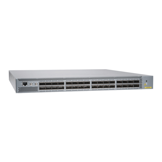
The QFX5220-32CD offers 32 ports of 400-Gigabit Ethernet in a low-profile 1 U form factor. With 12.8 Tbps bandwidth,
the QFX5220-32CD is optimally designed for spine-leaf deployments in enterprise, service provider, and cloud data
centers. The high-speed ports support a wide variety of port configurations that include 400-Gbps, 100-Gbps, 25-Gbps,
40-Gbps, and 10-Gbps.
®
®
An Intel
Xeon
D-1500 processor drives the QFX5220 control plane, which runs the Junos OS Evolved software. The
Junos OS Evolved software image is stored on two internal 50 GB solid-state drives (SSDs). The QFX5220-32CD is available
with either ports-to-FRUs or FRUs-to-ports airflow and with AC power supplies.
Advertisement
Table of Contents

Subscribe to Our Youtube Channel
Related Manuals for Juniper QFX5220-32CD


Summary of Contents for Juniper QFX5220-32CD
-
Page 1: Table Of Contents
QFX5220-32CD Safety Warning Summary | 9 System Overview The QFX5220-32CD offers 32 ports of 400-Gigabit Ethernet in a low-profile 1 U form factor. With 12.8 Tbps bandwidth, the QFX5220-32CD is optimally designed for spine-leaf deployments in enterprise, service provider, and cloud data centers. -
Page 2: Tools And Parts Required For Installation
Register product serial numbers on the Juniper Networks website and update the installation base data if there is any addition or change to the installation base or if the installation base is moved. Juniper Networks will not be held accountable for not meeting the hardware replacement service-level agreement for products that do not have registered serial numbers or accurate installation base data. -
Page 3: Part 1: Mount The Switch Into A 4-Post Rack
To mount the QFX5220-32CD on a four post rack using the provided rack mount kit: 1. Attach the ESD grounding strap to your bare wrist and to a site ESD point. - Page 4 QFX5220-32CD. Figure 2: Attach QFX5220-32CD to Rack 8. Continue to support the switch while sliding the mounting blades into the channel of the mounting rails and securing the blades to the rack.
-
Page 5: Part 2: Ground The Chassis And Connect Power
Attach the lug through the left rail and blade assembly to the chassis. The posts on the grounding lug should point to the left. See Figure Figure 4: Connecting a Grounding Cable to a QFX5220-32CD 2. Connect the remaining end of the grounding cable to a proper earth ground, such as the rack in which the switch is mounted. - Page 6 3. Locate the power cords shipped with the switch; the cords have plugs appropriate for your geographical location. See AC Power Cord with Type C15 Coupler Specifications. For each power supply: a. Ensure the loop on the power cord retainer is open and there is enough space to insert the power cord coupler into the inlet.
-
Page 7: Part 3: Connect The Qfx5220-32Cd To The Network And Perform The Initial Configuration
Perform the Initial Configuration Connect the QFX5220-32CD to your network for out-of-band management: 1. Connect one end of the Ethernet cable to the management port (labeled Mgmt) on the QFX5220-32CD. 2. Connect the other end of the Ethernet cable to the management device. - Page 8 NOTE: On the QFX5220-32CD, the management port re0:mgmt-0 is the bottom RJ-45 port on the right side of the port panel and is labeled MGMT. 8. Create the mgmt_junos routing instance.
-
Page 9: Qfx5220-32Cd Safety Warning Summary
Before connecting the switch to a power source, read the installation instructions in the QFX5220 documentation. The QFX5220-32CD weighs approximately 24.5 lbs (11.11 kg. Manually installing the QFX5220-32CD in a rack or cabinet at a height above 60 in. (152.4 cm) requires two people to lift the switch and install mounting screws. To prevent... - Page 10 The attached power cable is only for this product. Do not use the cable for another product. In the event of a hardware failure, please contact Juniper Networks, Inc. to obtain a Return Material Authorization (RMA) number. This number is used to track the returned material at the factory and to return repaired or new components to the customer as needed.
Need help?
Do you have a question about the QFX5220-32CD and is the answer not in the manual?
Questions and answers