Table of Contents
Advertisement
Advertisement
Table of Contents

Related Manuals for Thermo Scientific LCQ Fleet


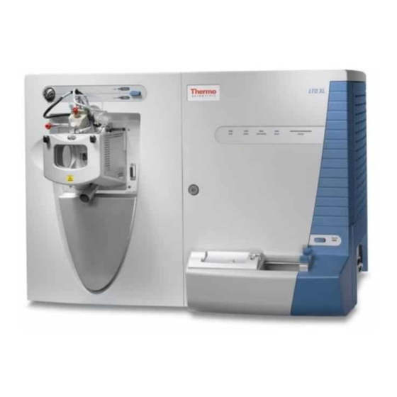
Summary of Contents for Thermo Scientific LCQ Fleet
- Page 1 LTQ Series Getting Connected Guide 97055-97071 Revision A January 2008...
- Page 2 © 2007 Thermo Fisher Scientific Inc. All rights reserved. Xcalibur, Surveyor, SpectraSYSTEM, and Accela are registered trademarks of Thermo Fisher Scientific Inc. in the United States. LCQ, LXQ, Fleet, LTQ, and IonMax are trademarks of Thermo Fisher Scientific Inc. The following are registered trademarks in the United States and other countries. Microsoft and Windows are registered trademarks of Microsoft Corporation.
- Page 3 Thermo Fisher Scientific or one of its authorized representatives. This document contains the testing and evaluation results for these Thermo Scientific products: • LCQ Fleet (March 2007) •...
- Page 4 LXQ (February 2005) EMC - Directive 89/336/EEC as amended by 92/31/EEC and 93/68/EEC EMC compliance has been evaluated by U.L. Underwriter’s Laboratory Inc. EN 55011: 1998 EN 61000-4-3: 2002, A1: 2002 EN 61000-3-2: 1995, A1: 1998, A2: 1998, A14: 2000 EN 61000-4-4: 1995, A1: 2001, A2: 2001 EN 61000-3-3: 1995 EN 61000-4-5: 1995, A1: 2001...
-
Page 5: En 61000-3-3: 1995,
LTQ XL with the ETD module (January 2007) EMC Directive 89/336/EEC EMC compliance has been evaluated by TUV Rheinland of North America, Inc. EN 61000-3-2: 1995, A1: 1998, A2: 1998, A14: 2000 EN 61000-4-4:1995, A1: 2000, A2:2001 EN 61000-3-3: 1995, A1:2001 EN 61000-4-5: 1995, A1: 2001 EN 61326-1: 1997, A1:1998, A2:2001, A3:2003 EN 61000-4-6: 2003... - Page 6 Notice on Lifting and Handling of Thermo Scientific Instruments For your safety, and in compliance with international regulations, the physical handling of this Thermo Fisher Scientific instrument requires a team effort to lift and/or move the instrument.
- Page 7 WEEE Compliance This product is required to comply with the European Union’s Waste Electrical & Electronic Equipment (WEEE) Directive 2002/96/EC. It is marked with the following symbol: Thermo Fisher Scientific has contracted with one or more recycling or disposal companies in each European Union (EU) Member State, and these companies should dispose of or recycle this product.
- Page 8 Conformité DEEE Ce produit doit être conforme à la directive européenne (2002/96/EC) des Déchets d'Equipements Electriques et Electroniques (DEEE). Il est marqué par le symbole suivant: Thermo Fisher Scientific s'est associé avec une ou plusieurs compagnies de recyclage dans chaque état membre de l’union européenne et ce produit devrait être collecté...
-
Page 9: Table Of Contents
Connecting the MS Detector to Line Power ......1 Connecting the Forepump to the LCQ Fleet or LXQ MS Detector ..2 Connecting the Vacuum Hose. - Page 10 Chapter 5 Connecting a Thermo Scientific LC System .......33 Contact Closure Cables ......... . . 34 Making Contact Closure with a Surveyor Plus LC System .
-
Page 11: Preface
In addition, this guide provides information on how to connect external devices, both those controlled from or independent of the Xcalibur data system. The LTQ Series includes the following Thermo Scientific mass spectrometers: • The LCQ™ Fleet™, a 3D ion trap mass spectrometer. -
Page 12: Safety And Special Notices
Preface Table 1. LTQ Series MS documentation Model Related Documents LCQ Fleet LCQ Fleet Getting Started Guide LCQ Fleet Hardware Guide LTQ XL LTQ XL Getting Started Guide LTQ XL Hardware Guide LTQ XL/ETD MS/ETD System Getting Started Guide MS/ETD System Getting Connected Guide... -
Page 13: Contacting Us
Web site www.thermo.com/finnigan To suggest changes to documentation or to Help • Fill out a reader survey online at www.thermo.com/lcms-techpubs. • Send an e-mail message to the Technical Publications Editor at techpubs.finnigan-lcms@thermofisher.com. Thermo Scientific LTQ Series Getting Connected Guide xiii... -
Page 15: Line Power, Vacuum System, Gases, And Ethernet Communication
Contents • Connecting the MS Detector to Line Power • Connecting the Forepump to the LCQ Fleet or LXQ MS Detector • Connecting the Forepumps to the LTQ XL MS Detector • Connecting the Gases to the MS Detector •... -
Page 16: Connecting The Forepump To The Lcq Fleet Or Lxq Ms Detector
Line Power, Vacuum System, Gases, and Ethernet Communication Connecting the Forepump to the LCQ Fleet or LXQ MS Detector Connecting the Forepump to the LCQ Fleet or LXQ MS Detector To connect the forepump (also known as a mechanical pump or rotary-vane pump) to the MS detector and the laboratory exhaust system, follow these procedures: •... - Page 17 Centering ring Centering ring To connect the forepump to the LCQ Fleet or LXQ MS detector 1. To connect the vacuum hose to the MS detector: a. Place the 41-mm (1.6-in.) ID centering ring (P/N 00108-02-00005) on the flange of the vacuum port located on the rear panel of the MS detector.
-
Page 18: Connecting The Forepump To The Laboratory Exhaust System
Line Power, Vacuum System, Gases, and Ethernet Communication Connecting the Forepump to the LCQ Fleet or LXQ MS Detector Connecting the Forepump to the Laboratory Exhaust System The proper operation of your forepump requires an efficient fume exhaust system. Most atmospheric pressure ionization (API) applications contribute to the accumulation of solvents in the forepump. -
Page 19: Connecting The Forepump To Line Power
Line Power, Vacuum System, Gases, and Ethernet Communication Connecting the Forepump to the LCQ Fleet or LXQ MS Detector Connecting the Forepump to Line Power The forepump gets its line power from the MS detector. The power outlet for the forepump is located on the power panel of the MS detector. -
Page 20: Connecting The Forepumps To The Ltq Xl Ms Detector
Locate the Main Power circuit breaker switch on the power panel and switch the circuit breaker to the Off position. b. Connect the power cords attached to the forepumps to the forepump outlets located on the power panel. LTQ Series Getting Connected Guide Thermo Scientific... -
Page 21: Connecting The Gases To The Ms Detector
For information on modifying the nitrogen line connections inside the MALDI LTQ XL system, contact your Thermo Fisher Scientific field service engineer. The MALDI LTQ XL system uses nitrogen to maintain the pressure in the upper sample compartment of the MALDI sample module. Thermo Scientific LTQ Series Getting Connected Guide... -
Page 22: Connecting The Helium Source
2. Connect the opposite end of the tubing to the helium gas source, using an appropriate fitting. Figure 5. Proper orientation of the Swagelok-type nut and two-piece ferrule Gas hose Front ferrule Swagelok-type nut Back ferrule For more information, visit: http://www.matheson-trigas.com LTQ Series Getting Connected Guide Thermo Scientific... -
Page 23: Connecting The Ms Detector To The Data System Computer
(P/N 00825-01015) provided with the MS detector. 3. Connect a second Ethernet cable (P/N 00302-01838) from the Ethernet switch to the Ethernet card on the data system computer labeled Surveyor MS. 4. Connect the Ethernet switch to line power. Thermo Scientific LTQ Series Getting Connected Guide... -
Page 25: Connecting Probes
(blue) exhaust tubing from the forepump to a dedicated fume exhaust system. Route the PVC drain tube from the API source to the waste container. Vent the waste container to a dedicated fume exhaust system that is independent from that used for exhausting the forepump. Thermo Scientific LTQ Series Getting Connected Guide... -
Page 26: Connecting The Apci Probe To The Ms Detector
Note If you need to install or replace the APCI sample tube, refer to the hardware manual for your Thermo Scientific mass spectrometer. LTQ Series Getting Connected Guide Thermo Scientific... -
Page 27: Connecting The Maldi Ltq Xl System
Connecting the MALDI LTQ XL System Forepumps to Line Power • Connecting the MALDI LTQ XL Vacuum System • Connecting the MALDI Control Module to the MALDI LTQ XL System • Connecting the MALDI CCD Camera to the Data System Computer Thermo Scientific LTQ Series Getting Connected Guide... -
Page 28: Connecting The Maldi Ltq Xl System Forepumps To Line Power
WARNING Motors Power Finnigan MAT PASS Ground Continuity and HPOT Tests Date: Power In Vacuum Pump From LTQ Accessory Outlet ONLY! Power cable Power cable Power switch Power switch Primary forepump Secondary forepump LTQ Series Getting Connected Guide Thermo Scientific... -
Page 29: Connecting The Maldi Ltq Xl Vacuum System
97155-60088 (contains the plug that terminates the extra section of vacuum hose) Figure 7. MALDI solenoid vacuum valve assembly Adapter Hose clamp Vacuum hose Centering ring Clamp Adapter Solenoid vacuum valve Hose clamp Thermo Scientific LTQ Series Getting Connected Guide... - Page 30 Oil Mist Filter EMF 20 Oil Mist Filter EMF 20 EDWARDS EDWARDS Primary Secondary forepump forepump Vacuum hose terminated with an 0-ring, plug, Vacuum connection between the LTQ XL MS detector and clamp and the primary forepump LTQ Series Getting Connected Guide Thermo Scientific...
-
Page 31: Connecting The Maldi Control Module To The Maldi Ltq Xl System
(42 in.) 97155-63082 Sensor cable 1.1 m (42 in.) 97155-63026 Laser communications cable 97 cm (36 in.) 97155-63101 Laser power cable 1.1 m (42 in.) 97155-63102 MALDI/LTQ Comm cable 1.1 m (42 in.) Thermo Scientific LTQ Series Getting Connected Guide... - Page 32 Power Finnigan MAT PASS CCD Camera Ground Continuity and HPOT Tests Date: Laser Comm Laser Power Power In Vacuum Pump From LTQ Accessory Outlet ONLY! Laser power cable Laser communications cable Motors cable LTQ Series Getting Connected Guide Thermo Scientific...
- Page 33 (rear panel) MODEL:MALDI Laser Control Module CAUTION SERIAL No: DISCONNECT WARNING Power Finnigan MAT PASS Ground Continuity and HPOT Tests Date: Power In Vacuum Pump From LTQ Accessory Outlet ONLY! Power cable (P/N 00302-05-00002) Thermo Scientific LTQ Series Getting Connected Guide...
-
Page 34: Connecting The Maldi Ccd Camera To The Data System Computer
Figure 12 Figure 13 show, a video signal cable (P/N 97155-63110) connects the video output from the MALDI CCD camera to the data system computer. Figure 12. Video signal cable 3.0 m (120 in.) LTQ Series Getting Connected Guide Thermo Scientific... - Page 35 Connect the Osprey cable connector to the the computer’s video port Osprey cable Video signal cable Connect one end of the video signal cable to the yellow monitor connector of the Osprey cable Thermo Scientific LTQ Series Getting Connected Guide...
-
Page 37: Connecting External Devices
Xcalibur Additional 4-Port Serial Kit OPTON-30018 Xcalibur JetDirect™ Ethernet Control Kit • Contact closure PCB • External contact closure cable • Ethernet 10 Base-T cable (2) • 10/100 Autosensing 8-port Ethernet switch • HP JetDirect 400N PCB Thermo Scientific LTQ Series Getting Connected Guide... -
Page 38: External Devices Controlled By The Xcalibur Data System
Making Contact Closure with Devices Controlled by Xcalibur Thermo Fisher Scientific provides instructions for connecting supported liquid chromatography systems to your Thermo Scientific mass spectrometer. You can access the appropriate instruction guide from the data system computer. To connect the contact closure cable 1. -
Page 39: Selecting The Appropriate Start Instrument
The Run Sequence dialog box appears. See Figure 14. The Yes in the Start Instrument column indicates that the Surveyor Autosampler will be used as the start instrument once the sequence run begins. Thermo Scientific LTQ Series Getting Connected Guide... - Page 40 The Change Instruments In Use dialog box appears, with, for example, the Surveyor Autosampler selected as the Start instrument. See Figure Figure 15. Change Instruments In Use dialog box with the Surveyor Autosampler selected as the start instrument LTQ Series Getting Connected Guide Thermo Scientific...
-
Page 41: External Devices Not Controlled By The Xcalibur Data System
External device power entry panel contact closure terminal TTL IN 1 Output (start) terminal DIGITAL GROUND Ground terminal Figure 16 shows a block diagram of the contact closure connection to an external device. Thermo Scientific LTQ Series Getting Connected Guide... -
Page 42: Starting A Sequence Run From Xcalibur
LTQ Series MS detector is not listed as the start instrument in Xcalibur. The LTQ Series family of MS detectors consists of the LCQ Fleet, LXQ, LTQ, and LTQ XL MS detectors. - Page 43 Figure 17 shows Yes under Start Instrument for the LCQ Fleet MS detector. Figure 17. Run Sequence dialog box with the MS detector specified as the start instrument 4. Click Change Instruments.
- Page 44 For example, you can control the SpectraSYSTEM™ AS3000 autosampler from its front panel command center. See Figure Note LC Devices does not include support for the Thermo Scientific SpectraSYSTEM LC modules, making the SpectraSYSTEM autosampler an external device not controlled by the Xcalibur data system.
- Page 45 Front panel command center ST ATUS MENU ST ATUS MENU ST ATUS MENU STOP STOP STOP ENTER ENTER ENTER SpectraSYSTEM P4000 AS3000 SpectraSYSTEM UV2000 PURGE SAMPLES SpectraSYSTEM ZERO Degasser Pump Autosampler Detector Pump Autosampler Detector Degasser Thermo Scientific LTQ Series Getting Connected Guide...
-
Page 47: Chapter 5 Connecting A Thermo Scientific Lc System
Connecting a Thermo Scientific LC System This chapter describes how to make the contact closure connections between a Surveyor Plus™ or an Accela™ LC system and the LTQ Series MS detector. Note The 7-connector LC/MS interconnect cable is described in this chapter. For instructions on using the 5-connector LC/MS interconnect cable, refer to the Surveyor Plus Getting Connected Guide. -
Page 48: Contact Closure Cables
Connecting a Thermo Scientific LC System Contact Closure Cables Contact Closure Cables To make contact closure with a Thermo Scientific LC /MS system, you must have these contact closure cables: • The LC/MS interconnect cable shown in Figure • The LTQ/LXQ interconnect adapter cable shown in... -
Page 49: Making Contact Closure With A Surveyor Plus Lc System
Connecting a Thermo Scientific LC System Making Contact Closure with a Surveyor Plus LC System Making Contact Closure with a Surveyor Plus LC System Table 6 lists the firmware for the Surveyor Plus LC devices supported by the Xcalibur 2.0.5 or higher data system. - Page 50 Connecting a Thermo Scientific LC System Making Contact Closure with a Surveyor Plus LC System 3. To connect a Surveyor MS Pump or Surveyor MS Pump Plus to the LC/MS interconnect cable: a. Connect the end of the adapter cable labeled PUMP to one of the PUMP connectors of the 7-connector LC/MS interconnect cable.
-
Page 51: Making Contact Closure With An Accela Lc System
Connecting a Thermo Scientific LC System Making Contact Closure with an Accela LC System Making Contact Closure with an Accela LC System Table 7 lists the firmware for the Accela LC devices supported by the Xcalibur 2.0.5 or higher data system. The LC Devices software CD contains the instrument control software for these devices. - Page 52 Connecting a Thermo Scientific LC System Making Contact Closure with an Accela LC System Figure 24. Accela LC connected to an LCQ Fleet MS detector Solvent platform MS Detector Detector Detector Detector PDA detector Autosampler Pump (rear panel) Pump 7-connector LC/MS Interconnect cable...
-
Page 53: Chapter 6 Connecting The Inlet Plumbing
5 of the valve. To introduce sample into the ion source, load sample into the sample loop through the loop filler, and then switch the position of the injection valve, allowing the solvent stream to backflush the contents of the sample loop into the ion source. Thermo Scientific LTQ Series Getting Connected Guide... - Page 54 53 LC system with autosampler Analysis of a mixture Analysis of a mixture “Setting Up the Inlet for an (with LC column for LC/MS System with an chromatographic separations) Autosampler” page 53 LTQ Series Getting Connected Guide Thermo Scientific...
-
Page 55: Fittings, Tubing, Unions, And Sample Loops
(used with fused-silica tubing and the blunt-tip, 34-gauge stainless steel needle included in Metal Needle Kit) Ferrule, Kel-F, 0.012-in. ID, Upchurch Scientific (clear) 00101-18116 (used with blunt-tip, 32-gauge stainless steel needle included in Metal Needle Kit) Thermo Scientific LTQ Series Getting Connected Guide... - Page 56 30° ports 50 μL sample loop, stainless steel, Rheodyne 00110-22016 100 μL sample loop, stainless steel, Rheodyne 00110-22018 500 μL sample loop, stainless steel, Rheodyne 00110-22020 1 mL sample loop, stainless steel, Rheodyne 00110-22022 LTQ Series Getting Connected Guide Thermo Scientific...
-
Page 57: Setting Up The Inlet For Direct Infusion
Connecting an Infusion Line to the Grounding Union Figure 25. Connection between the ESI probe and the syringe pump Connection between infusion line and ESI probe Connection between syringe pump and infusion line Thermo Scientific LTQ Series Getting Connected Guide... -
Page 58: Setting Up The Syringe
2. Connect the other end of the infusion line with a fingertight fitting (for a 10-32 port and 1/16-in. OD tubing) and a ferrule to the grounding union. Figure 27 shows the connection between the grounding union and the LC union made with red PEEK tubing and fingertight fittings. LTQ Series Getting Connected Guide Thermo Scientific... -
Page 59: Setting Up The Inlet For High-Flow Infusion
Connecting the Union Tee to the Divert/Inject Valve • Connecting the LC Pump to the Divert/Inject Valve • Connecting the Divert/Inject Valve to a Waste Container • Connecting the Union Tee to the Ion Source Thermo Scientific LTQ Series Getting Connected Guide... -
Page 60: Connecting The Syringe To The Union Tee
LC union to the union Tee. Figure 28. Connecting the LC union to the union Tee Union Tee (P/N 00101-18204) Ferrule (P/N 00101-18196) Fingertight fitting (P/N 00101-18081) Ferrule (P/N 00101-18196) LC union Syringe Fingertight fitting (P/N 00101-18081) LTQ Series Getting Connected Guide Thermo Scientific... -
Page 61: Connecting The Union Tee To The Divert/Inject Valve
2. Using a fingertight fitting and a ferrule, connect the other end of the tubing to the free end of the union Tee. See Figure 29 Figure Figure 29. Six-port divert/inject valve connections LC TEE union union Tee From From Plug Plug (optional) (optional) waste waste Detector position Waste position Thermo Scientific LTQ Series Getting Connected Guide... -
Page 62: Connecting The Lc Pump To The Divert/Inject Valve
1. Using a fingertight fitting and a ferrule, connect a length of red PEEK tubing to port 1 of the divert/inject valve. Figure 29 shows the ports of the divert/inject valve. 2. Insert the other end of the tubing into a suitable waste container. LTQ Series Getting Connected Guide Thermo Scientific... -
Page 63: Connecting The Union Tee To The Ion Source
The grounding union slides into the grounding bar on the Ion Max-S API source as shown in Figure 38 page 55. For instructions on connecting the grounding union to the ESI probe sample inlet, refer to the Ion Max and Ion Max-S API Source Hardware Manual. Thermo Scientific LTQ Series Getting Connected Guide... - Page 64 Figure 33. Plumbing diagram showing ESI/MS sample introduction with high-flow infusion From LC pump outlet to port 2 From port 1 to waste container From port 3 to TEE From TEE to grounding union From syringe to TEE LTQ Series Getting Connected Guide Thermo Scientific...
-
Page 65: Setting Up The Inlet For Loop Injections (Flow Injection Analyses)
LC pump outlet and the divert/inject valve. • Using a fingertight fitting and a ferrule, connect the other end of the tubing to port 2 of the divert/inject valve. Thermo Scientific LTQ Series Getting Connected Guide... - Page 66 Connection between port 2 of the divert/inject valve and the LC pump Connection between port 3 of the divert/inject valve and the sample inlet of the APCI probe Load Detector Inject Waste Waste line Loop filler LTQ Series Getting Connected Guide Thermo Scientific...
-
Page 67: Setting Up The Inlet For An Lc/Ms System With An Autosampler
1. Using an appropriate fitting and ferrule, connect one end of a length of red PEEK tubing to the outlet of your LC system. 2. Using a fingertight fitting and a ferrule, connect the other end of the tubing to port 2 of the divert/inject valve. See Figure Thermo Scientific LTQ Series Getting Connected Guide... - Page 68 • Using a fingertight fitting and a ferrule, connect one end of a length of red PEEK tubing to port 1 of the divert/inject valve. • Place the other end of the tubing to an appropriate waste container. LTQ Series Getting Connected Guide Thermo Scientific...
-
Page 69: Connecting The Grounding Union To The Esi Probe Sample Inlet
ESI probe sample inlet, refer to the Ion Max and Ion Max-S API Source Hardware Manual. Figure 38. Connecting the grounding union to the sample inlet of the ESI probe Sample inlet Grounding Grounding union Thermo Scientific LTQ Series Getting Connected Guide... -
Page 71: Connecting The 4-Port Serial Pcb
Xcalibur Additional 4-Port Serial Kit • 4-port serial PCB (PCI) and software • Quad DB (male adapter) Figure 39. 4-port serial PCB and quad DB9 male cable 4-port serial PCB Quad DB9 male cable Thermo Scientific LTQ Series Getting Connected Guide... - Page 72 10. Restart the data system computer. The 4-port serial PCB is a Plug-and-Play device. When Windows XP starts, it automatically detects and configures the new 4-port serial PCB and loads the appropriate drivers. LTQ Series Getting Connected Guide Thermo Scientific...
-
Page 73: Index
Info view in Xcalibur, displaying direct infusion, setting up the plumbing connections infusion line, connecting to grounding union divert/inject valve interconnect cables for a Thermo Scientific LC/MS connecting to union Tee connecting to waster container kits for additional 4-port serial PCB... - Page 74 Index: M LCQ Fleet or LXQ, connecting the forepump line power trigger, 2-wire (contact closure), connection for inlet devices MALDI control module, connecting not supported by Xcalibur MALDI LTQ XL system forepumps tubing MS detector, connecting loop injections, setting up...
Need help?
Do you have a question about the LCQ Fleet and is the answer not in the manual?
Questions and answers