Siemens S120 Manual
Hide thumbs
Also See for S120:
- Function manual (1094 pages) ,
- Diagnostic manual (947 pages) ,
- Manual (848 pages)
Table of Contents
Advertisement
Quick Links
Advertisement
Table of Contents

Related Manuals for Siemens S120


Summary of Contents for Siemens S120
- Page 3 AC Drive Foreword Fundamental safety ___________________ instructions ___________________ System overview SINAMICS Mains connection and line- ___________________ side power components S120 ___________________ AC Drive Power Modules ___________________ DC link components Manual Motor-side power ___________________ components Control Units, Control Unit Adapters and operating...
- Page 4 Note the following: WARNING Siemens products may only be used for the applications described in the catalog and in the relevant technical documentation. If products and components from other manufacturers are used, these must be recommended or approved by Siemens. Proper transport, storage, installation, assembly, commissioning, operation and maintenance are required to ensure that the products operate safely and without any problems.
-
Page 5: Foreword
Siemens content, and adapt it for your own machine documentation: http://www.siemens.com/mdm Training At the following link, you will find information on SITRAIN - training from Siemens for products, systems, and drive and automation engineering solutions: http://www.siemens.com/sitrain FAQs You can find Frequently Asked Questions in the Service&Support pages under Product... - Page 6 Equipment for Machine Tools (Catalog NC 61) SINUMERIK 840D sl Type 1B • Equipment for Machine Tools (Catalog NC 62) Configuring/installation SINAMICS S120 Equipment Manual for Control Units and • Additional System Components SINAMICS S120 Equipment Manual for Booksize Power •...
- Page 7 SINAMICS drive system. Benefits This Manual provides all the information, procedures and operational instructions required for commissioning and servicing SINAMICS S120. Standard scope The scope of the functionality described in this document can differ from the scope of the functionality of the drive system that is actually supplied.
- Page 8 Foreword The EC Declaration of Conformity for the Low Voltage Directive can be found on the Internet http://support.automation.siemens.com There – as a search term – enter the number 22383669 . Note When operated in dry areas, SINAMICS S units conform to the Low-Voltage Directive 2006/95/EC.
- Page 9 Foreword Explanation of symbols Table 2 Symbols Symbol Meaning Protective earth (PE) Ground (e.g. M 24 V) Functional ground Equipotential bonding AC Drive Manual, (GH6), 04/2014, 6SL3097-4AL00-0BP4...
- Page 10 Foreword AC Drive Manual, (GH6), 04/2014, 6SL3097-4AL00-0BP4...
-
Page 11: Table Of Contents
System overview ........................... 29 Field of application ........................29 Platform Concept and Totally Integrated Automation ..............31 Overview, SINAMICS S120 AC Drive ..................32 SINAMICS S120 components ...................... 33 System data ..........................35 Derating as a function of the ambient temperature, pulse frequency, and installation altitude ............................ - Page 12 Table of contents 3.8.3 Dimension drawings ........................58 3.8.4 Mounting............................64 3.8.5 Electrical Connection ........................71 3.8.6 Technical data ..........................72 3.8.6.1 Blocksize line reactors ........................ 72 3.8.6.2 Chassis line reactors ........................75 Line connection variants ......................76 3.9.1 Operation on different line system configurations ............... 76 3.9.2 Methods of line connection ......................
- Page 13 Table of contents Power Modules Chassis ......................159 4.4.1 Description ..........................159 4.4.2 Safety instructions for Power Modules chassis format .............. 159 4.4.3 Interface description ........................160 4.4.3.1 Overview ............................ 160 4.4.3.2 Connection example ........................162 4.4.3.3 Terminal Block X9 ........................163 4.4.3.4 DCPS, DCNS connection for a dv/dt filter .................
- Page 14 Table of contents 6.1.1.3 Dimension drawings ........................213 6.1.1.4 Mounting............................ 221 6.1.1.5 Electrical connection ......................... 227 6.1.1.6 Technical data ........................... 228 Chassis ............................231 6.2.1 Motor reactors ........................... 231 6.2.1.1 Description ..........................231 6.2.1.2 Safety instructions for motor reactors ..................231 6.2.1.3 Dimension drawing ........................
- Page 15 Table of contents 7.3.2.13 S5 DIP switch ..........................279 7.3.2.14 DIAG button ..........................279 7.3.2.15 RESET button ..........................279 7.3.2.16 Memory card ..........................280 7.3.3 Connection examples ........................ 281 7.3.4 Meaning of the LEDs ......................... 283 7.3.4.1 Function of the LEDs ......................... 283 7.3.4.2 Behavior of the LEDs during booting ..................
- Page 16 Table of contents 7.6.2 Interface description ........................324 7.6.2.1 Overview ........................... 324 7.6.2.2 X200-X202 DRIVE-CLiQ interfaces ..................325 7.6.2.3 X210 EP terminal / temperature sensor ..................326 7.6.2.4 X220 HTL/TTL/SSI encoder interface ..................327 7.6.2.5 X224 electronics power supply ....................329 7.6.3 Connection example .........................
- Page 17 Table of contents 8.2.6 Mounting ............................ 382 8.2.7 Technical data ..........................383 Safe Brake Adapter optional module ..................384 8.3.1 Description ..........................384 8.3.2 Safety instructions for Safe Brake Adapters ................385 8.3.3 Interface description ........................386 8.3.3.1 Overview ............................ 386 8.3.3.2 X11 interface to the Control Interface Module ................
- Page 18 Table of contents 10.3 Notes on electromagnetic compatibility (EMC) ................. 419 10.4 Cable shielding and routing....................... 420 10.5 24 V DC Supply Voltage ......................422 10.5.1 General ............................422 10.5.2 Overcurrent protection ......................423 10.5.3 Overvoltage protection ......................424 10.5.4 Typical 24 V current consumption of the components ..............
- Page 19 Table of contents 11.3.3.2 Replacing the Powerblock, Power Module, frame size GX ............469 11.3.3.3 Replacing the Control Interface Module, Power Module, frame size FX ........472 11.3.3.4 Replacing the Control Interface Module, Power Module, frame size GX ........474 11.3.3.5 Replacing the fan, Power Module, frame size FX ..............
- Page 20 Table of contents AC Drive Manual, (GH6), 04/2014, 6SL3097-4AL00-0BP4...
-
Page 21: Fundamental Safety Instructions
Fundamental safety instructions General safety instructions DANGER Danger to life due to live parts and other energy sources Death or serious injury can result when live parts are touched. • Only work on electrical devices when you are qualified for this job. •... - Page 22 Fundamental safety instructions 1.1 General safety instructions WARNING Danger to life when live parts are touched on damaged devices Improper handling of devices can cause damage. For damaged devices, hazardous voltages can be present at the enclosure or at exposed components;...
- Page 23 Fundamental safety instructions 1.1 General safety instructions WARNING Danger to life through unexpected movement of machines when using mobile wireless devices or mobile phones Using mobile wireless devices or mobile phones with a transmit power > 1 W closer than approx.
-
Page 24: Safety Instructions For Electromagnetic Fields (Emf)
Fundamental safety instructions 1.2 Safety instructions for electromagnetic fields (EMF) NOTICE Device damage caused by incorrect voltage/insulation tests Incorrect voltage/insulation tests can damage the device. • Before carrying out a voltage/insulation check of the system/machine, disconnect the devices as all converters and motors have been subject to a high voltage test by the manufacturer, and therefore it is not necessary to perform an additional test within the system/machine. -
Page 25: Handling Electrostatic Sensitive Devices (Esd)
Note Industrial security Siemens provides automation and drive products with industrial security functions that support the secure operation of plants or machines. They are an important component in a holistic industrial security concept. With this in mind, our products undergo continuous development. -
Page 26: Residual Risks Of Power Drive Systems
• Keep the software up to date. Information and newsletters can be found at: http://support.automation.siemens.com • Incorporate the automation and drive components into a state-of-the-art, integrated industrial security concept for the installation or machine. For more detailed information, go to: http://www.siemens.com/industrialsecurity... - Page 27 Fundamental safety instructions 1.5 Residual risks of power drive systems 2. In the event of a fault, exceptionally high temperatures, including an open fire, as well as emissions of light, noise, particles, gases, etc. can occur inside and outside the inverter, e.g.: –...
-
Page 29: System Overview
System overview Field of application SINAMICS is the family of drives from Siemens designed for machine and plant engineering applications. SINAMICS offers solutions for all drive tasks: ● Simple pump and fan applications in the process industry. ● Complex single drives in centrifuges, presses, extruders, elevators, as well as conveyor and transport systems ●... - Page 30 System overview 2.1 Field of application Depending on the application, the SINAMICS range offers the ideal version for any drive task. ● SINAMICS G is designed for standard applications with induction motors. These applications have less stringent requirements regarding the dynamic performance of the motor speed.
-
Page 31: Platform Concept And Totally Integrated Automation
SINAMICS S120 variants. It provides a high-performance, system-wide communication network which links all automation components: HMI, controls, drives and I/O devices. SINAMICS S120 is also available with a PROFINET interface. This Ethernet-based bus allows the rapid exchange of control data via PROFINET IO. -
Page 32: Overview, Sinamics S120 Ac Drive
System overview 2.3 Overview, SINAMICS S120 AC Drive Overview, SINAMICS S120 AC Drive SINAMICS S120 AC Drive is a modular drive system for individual axes and addresses sophisticated drive tasks for an extremely wide range of industrial applications. Applications include: ●... -
Page 33: Sinamics S120 Components
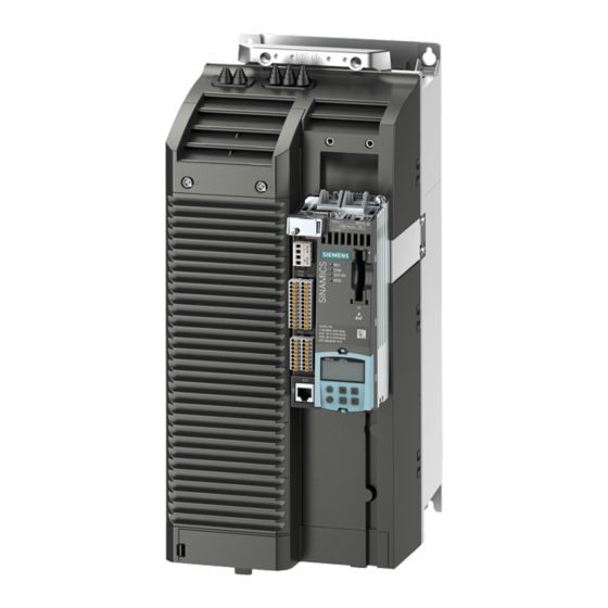
System overview 2.4 SINAMICS S120 components SINAMICS S120 components Figure 2-3 SINAMICS S120 component overview AC Drive Manual, (GH6), 04/2014, 6SL3097-4AL00-0BP4... - Page 34 ● Power Modules (either with or without integrated line filter) and an integrated braking chopper to provide power to the connected motor To address the required functions, SINAMICS S120 AC Drive is equipped with: ● Control Units that provide the drive and technological functions ●...
-
Page 35: System Data
• ≥ 1194 kW: 200 kA • For Blocksize and Chassis components, UL certification applies only in conjunction with the fuses prescribed by Siemens and not with other types or just with circuit-breakers. Electromagnetic compatibility Category C3 (option) according to EN 61800-3... - Page 36 System overview 2.5 System data Table 2- 2 Environmental conditions Degree of protection IPXXB according to EN 60529, open type according to UL 508 Protection class, line supply circuits I (with protective conductor connection) Electronic circuits safety extra-low voltage PELV / SELV Type of cooling Internal air cooling, power units with forced air cooling using an integrated fan...
-
Page 37: Derating As A Function Of The Ambient Temperature, Pulse Frequency, And Installation Altitude
System overview 2.6 Derating as a function of the ambient temperature, pulse frequency, and installation altitude Derating as a function of the ambient temperature, pulse frequency, and installation altitude Preliminary remark The air pressure and therefore the air density drop at altitudes above sea level. At these altitudes, the same quantity of air does not have the same cooling effect and the air gap between two electrical conductors can only insulate a lower voltage. - Page 38 System overview 2.6 Derating as a function of the ambient temperature, pulse frequency, and installation altitude AC Drive Manual, (GH6), 04/2014, 6SL3097-4AL00-0BP4...
-
Page 39: Mains Connection And Line-Side Power Components
Mains connection and line-side power components Introduction The following line-side components should be used to connect a SINAMICS drive line-up to the supply network: ● Line disconnector ● Overcurrent protection device (line fuses or circuit-breaker) ● Line contactor (this is required for electrical isolation) ●... -
Page 40: Information On The Disconnector Unit
Mains connection and line-side power components 3.2 Information on the disconnector unit Figure 3-1 Example of a Blocksize line connection Figure 3-2 Example of a chassis line connection Information on the disconnector unit A disconnector unit is required for disconnecting the drive line-up from the supply system correctly. -
Page 41: Overcurrent Protection By Means Of Line Fuses And Circuit Breakers
Mains connection and line-side power components 3.3 Overcurrent protection by means of line fuses and circuit breakers Overcurrent protection by means of line fuses and circuit breakers Line fuses or circuit-breakers must be used for cable protection/overcurrent protection. NH, D, and DO type fuses with a gL characteristic or suitable circuit-breakers according to IEC 60947 can be used for this purpose. -
Page 42: Overvoltage Protection
Mains connection and line-side power components 3.5 Overvoltage protection ● The shielded motor cable must not be longer than 50 m. ● Use a separate residual current operated circuit-breaker for each Power Module. ● Ensure that the switching elements (disconnector unit, contactors) for connecting and disconnecting the drive line-up have max. -
Page 43: Line Contactors
Mains connection and line-side power components 3.6 Line contactors Line contactors A line contactor is required if the drive line-up needs to be electrically isolated from the power supply. When selecting a line contactor, the characteristic values in the technical data apply. The cable routing, the bundling factor, and the factor for the ambient temperature according to EN 60204-1 must be taken into account when dimensioning the various cables. -
Page 44: Line Filter
In conjunction with a suitably EMC-compliant system configuration, line filters limit the conducted interference emitted by the Power Modules to limit values according to EN 61800- A line filter according to the catalog must be used for the SINAMICS S120 drive line-up. 3.7.2... -
Page 45: Electromagnetic Compatibility (Emc) Of The System
Mains connection and line-side power components 3.7 Line filter Category C3 Drive systems with a rated voltage < 1000 V, which are intended for use in the second environment and not for use in the first environment. Drive systems which correspond to category C3 may only be installed in the second environment. - Page 46 Mains connection and line-side power components 3.7 Line filter – shorter than 50 m for PM240-2 Power Modules. – shorter than 25 m for PM340 Power Modules. – shorter than 100 m for Chassis Power Modules. ● The pulse frequency is –...
-
Page 47: Safety Instructions For Line Filters
Damage of further loads due to incorrect line filters Unsuitable line filters can cause line harmonics, which damage or destroy loads connected to the same line supply. • Only use line filters released by SIEMENS for SINAMICS. AC Drive Manual, (GH6), 04/2014, 6SL3097-4AL00-0BP4... -
Page 48: Dimension Drawings
Mains connection and line-side power components 3.7 Line filter 3.7.5 Dimension drawings Blocksize line filter Figure 3-3 Dimension drawing of the line filter, Power Module PM240-2 frame size FSA, all data in mm (inches) AC Drive Manual, (GH6), 04/2014, 6SL3097-4AL00-0BP4... - Page 49 Mains connection and line-side power components 3.7 Line filter Figure 3-4 Dimension drawing of the line filter, Power Module PM240-2 frame size FSB, all data in mm (inches) AC Drive Manual, (GH6), 04/2014, 6SL3097-4AL00-0BP4...
- Page 50 Mains connection and line-side power components 3.7 Line filter Figure 3-5 Dimension drawing of the line filter, Power Module PM240-2 frame size FSC, all data in mm (inches) AC Drive Manual, (GH6), 04/2014, 6SL3097-4AL00-0BP4...
- Page 51 Mains connection and line-side power components 3.7 Line filter Figure 3-6 Dimension drawing of the line filter, PM340 Power Module frame size FSA, all data in mm (inches) AC Drive Manual, (GH6), 04/2014, 6SL3097-4AL00-0BP4...
- Page 52 Mains connection and line-side power components 3.7 Line filter Chassis line filter Figure 3-7 Dimension drawing, line filter Table 3- 1 Dimensions of the line filter, all data in mm and (inches) 6SL3000- 0BE32-5AA0 0BE34-4AA0 0BE36-0AA0 360 (14.17) 360 (14.17) 400 (15.74) 240 (9.44) 240 (9.44)
-
Page 53: Mounting
Mains connection and line-side power components 3.7 Line filter 3.7.6 Mounting The line filters are designed as base components. The line filter is retained on the mounting surface and the Power Module is mounted on the line filter in a space-saving fashion. The cables to the Power Modules are already connected at the line filter. -
Page 54: Technical Data
Mains connection and line-side power components 3.7 Line filter Table 3- 3 Connecting Power Module PM240-2 to the line filter Frame size Fastening Tightening torque 3 x M4 bolts 2.5 Nm 4 x M4 bolts 2.5 Nm 4 x M5 bolts 3 Nm 3.7.7 Technical data... -
Page 55: Technical Data, Chassis Line Filter
Mains connection and line-side power components 3.7 Line filter Table 3- 5 Technical data, Blocksize line filter PM340 Line voltage 3-phase 380 ... 480 VAC Line filter 6SE6400- 2FA00-6AD0 FSA Suitable for Power 6SL3210-1SE11-3UA0, 6SL3210-1SE11-7UA0 Module 6SL3210-1SE12-2UA0, 6SL3210-1SE13-1UA0 6SL3210-1SE14-1UA0 Rated current Power loss <... -
Page 56: Line Reactors
Mains connection and line-side power components 3.8 Line reactors Line reactors 3.8.1 Description The line reactors limit low-frequency line harmonics and reduce the load on the rectifiers in the Power Modules. They are used to smooth voltage spikes (line supply faults) or to bridge voltage dips/interruptions when commutating. - Page 57 Damage to the system due to impermissible line reactors An impermissible line reactor may cause damage to the system and any further loads operated on the same power network. • Only use line reactors that SIEMENS has released for SINAMICS. NOTICE Line reactor damage due to interchanged connections Interchanging the input and output connections will damage the line reactor.
-
Page 58: Dimension Drawings
Mains connection and line-side power components 3.8 Line reactors 3.8.3 Dimension drawings Blocksize line reactors for PM240-2 Figure 3-9 Dimensional drawing of line reactors, PM240-2 frame size FSA, 0.55 … 1.1 kW, all dimensions in mm and (inch) Figure 3-10 Dimensional drawing of line reactors, PM240-2 frame size FSA, 1.5 …... - Page 59 Mains connection and line-side power components 3.8 Line reactors Figure 3-11 Dimensional drawing of line reactors, PM240-2, frame size FSB, 4.0 … 7.5 kW, all dimensions in mm and (inch) Figure 3-12 Dimensional drawing of line reactors, PM240-2, frame size FSC, 11 … 15 kW, all dimensions in mm and (inch) AC Drive Manual, (GH6), 04/2014, 6SL3097-4AL00-0BP4...
- Page 60 Mains connection and line-side power components 3.8 Line reactors Blocksize line reactors for PM340 ① Frame size FSA ② Frame size FSB ③ Frame size FSC Figure 3-13 Dimension drawing of line reactors, PM340 frame sizes FSA, FSB, FSC Table 3- 7 Dimensions of line reactors, PM340 frame size FSA, all data in mm (inches) Line reactor 6SE6400- 3CC00-4AB3...
- Page 61 Mains connection and line-side power components 3.8 Line reactors ① Frame size FSD ② Frame size FSE Figure 3-14 Dimension drawing of line reactors, PM340 frame sizes FSD, FSE Table 3- 9 Dimensions of line reactors, PM340 frame sizes FSD and FSE, all data in mm (inches) Line reactor 6SL3203- 0CJ24-5AA0 0CD25-3AA0...
- Page 62 Mains connection and line-side power components 3.8 Line reactors Figure 3-15 Dimension drawing of line reactors, PM340 frame size FSF Table 3- 10 Dimensions of line reactors, PM340 frame size FSF, all data in mm (inches) Line reactor 6SE6400- 3CC11-2FD0 3CC11-7FD0 Frame size 240 (9.44)
- Page 63 Mains connection and line-side power components 3.8 Line reactors Chassis line reactors ① Mounting hole Figure 3-16 Dimension drawing, line reactors Table 3- 11 Dimensions of the line reactors, all data in mm (inches) 6SL3000- 0CE32-3AA0 0CE32-8AA0 0CE33-3AA0 0CE35-1AA0 25 (0.98) 25 (0.98) 25 (0.98) 30 (1.18)
-
Page 64: Mounting
Mains connection and line-side power components 3.8 Line reactors 3.8.4 Mounting Blocksize line reactors for PM240-2 The line reactors for Power Modules PM240-2 of frame sizes FSA to FSC are designed for installation in a cabinet. The line reactor is installed on the mounting surface next to the Power Module. - Page 65 Mains connection and line-side power components 3.8 Line reactors Blocksize line reactors for PM340 The line reactors for PM340 Power Modules in frame sizes FSA to FSE are designed as base components. The line reactor is fastened to the mounting surface and the Power Module is mounted on the line reactor in a space-saving fashion.
- Page 66 Mains connection and line-side power components 3.8 Line reactors Figure 3-18 Mounting dimensions of line reactor PM340, frame sizes FSB and FSC Table 3- 14 Mounting dimensions for line reactors PM340, frame sizes FSB and FSC, all data in mm and (inches) Line reactor 6SL3203- 0CD21-0AA0 0CD21-4AA0...
- Page 67 Mains connection and line-side power components 3.8 Line reactors Figure 3-19 Mounting dimensions of line reactor PM340, frame sizes FSD and FSE Table 3- 15 Mounting dimensions for line reactors PM340, frame sizes FSD and FSE, all data in mm and (inches) Line reactor 6SL3203- 0CD25-3AA0 0CJ24-5AA0...
- Page 68 Mains connection and line-side power components 3.8 Line reactors Figure 3-20 Mounting dimensions of line reactor PM340, frame size FSF Table 3- 16 Mounting dimensions of line reactor PM340, frame size FSF, all data in mm and (inches) Line reactor 6SE6400- 3CC11-2FD0 3CC11-7FD0 Frame size...
- Page 69 Mains connection and line-side power components 3.8 Line reactors Mounting examples Figure 3-21 Mounting the PM340 with a line reactor, using frame size FSB as an example ① Frame size FSB ② Frame size FSC ③ Lateral mounting bracket Figure 3-22 Lateral mounting of line reactors for frame sizes FSB and FSC AC Drive Manual, (GH6), 04/2014, 6SL3097-4AL00-0BP4...
- Page 70 Mains connection and line-side power components 3.8 Line reactors Figure 3-23 Mounting the PM340 with a line reactor, using frame size FSD as an example Chassis line reactors The line reactors for Power Modules, frame sizes FSF, FX, and GX are, as a result of their weight and their size, mounted separately.
-
Page 71: Electrical Connection
Mains connection and line-side power components 3.8 Line reactors 3.8.5 Electrical Connection Line/load connection ① Line reactor ② Power Module Figure 3-24 Power Module with line filter ① Line reactor ② Line filter ③ Power Module Figure 3-25 Power Module with line reactor and line filter AC Drive Manual, (GH6), 04/2014, 6SL3097-4AL00-0BP4... -
Page 72: Technical Data
Mains connection and line-side power components 3.8 Line reactors 3.8.6 Technical data 3.8.6.1 Blocksize line reactors Table 3- 17 Technical data of Blocksize line reactors PM240-2 Order No. 6SL3203- 0CE13-2AA0 0CE21-0AA0 0CE21-8AA0 0CE23-8AA0 Frame size Matching Power Line voltage 1-phase 200 VAC -10% to 240 VAC +10%: Modules 6SL3210- 6SL3210-... - Page 73 Mains connection and line-side power components 3.8 Line reactors Table 3- 18 Technical data, Blocksize line reactors PM340, frame size FSA Line voltage 1-phase 200 VAC -10% to 240 VAC +10% Order No. 6SE6400- 3CC00-4AB3 3CC01-0AB3 Suitable for Power Module 1SB11-0xxx 1SB14-0xxx 6SL3210-...
- Page 74 Mains connection and line-side power components 3.8 Line reactors Table 3- 20 Technical data, Blocksize line reactors PM340, frame sizes FSB and FSC Line voltage 3-phase 380 VAC -10% to 480 VAC +10% Frame size Order No. 6SL3203- 0CD21-0AA0 0CD21-4AA0 0CD22-2AA0 0CD23-5AA0 Suitable for...
-
Page 75: Chassis Line Reactors
Mains connection and line-side power components 3.8 Line reactors Table 3- 21 Technical data, Blocksize line reactors PM340, frame sizes FSD, FSE, and FSF Line voltage 3-phase 380 VAC -10% to 480 VAC +10% Frame size Order number 6SL3203- 6SL3203- 6SL3203- 6SE6400- 6SE6400-... -
Page 76: Line Connection Variants
Mains connection and line-side power components 3.9 Line connection variants Line connection variants 3.9.1 Operation on different line system configurations The Power Modules are designed for the following power distribution systems according to IEC 60364-1. Note Above an installation altitude of 2000 m, you must observe the notes in Section Derating as a function of the ambient temperature, pulse frequency, and installation altitude (Page 37). - Page 77 Mains connection and line-side power components 3.9 Line connection variants TT system In a TT system, a point of the generator or the transformer is grounded, normally the neutral point. The housing of the consumer is connected with the ground using a separate cable. Figure 3-27 TT system ●...
- Page 78 Mains connection and line-side power components 3.9 Line connection variants NOTICE Damage of the drive line-up when operating on an IT line system without motor reactor If the drive unit is operated without motor reactor on an IT line system, a ground fault on the motor side of the Power Modules can cause damage to the drive line-up or trigger the overcurrent protective equipment.
-
Page 79: Methods Of Line Connection
Mains connection and line-side power components 3.9 Line connection variants 3.9.2 Methods of line connection A distinction is made between the following line connection types: ● Line connection components to be directly connected to the line supply ● Operation of the line connection components via an autotransformer ●... - Page 80 Mains connection and line-side power components 3.9 Line connection variants Note Line connection of motors In combination with the drive system, the motors are generally approved for operation on TN and TT systems with grounded neutral point and on IT systems. In use on IT systems, the occurrence of a first fault between a live part and ground must be signaled by a monitoring device.
-
Page 81: Operation Of The Line Connection Components On The Supply Line
Mains connection and line-side power components 3.9 Line connection variants 3.9.3 Operation of the line connection components on the supply line The SINAMICS S drive system is designed to be directly connected to TN and TT systems with a grounded neutral point as well as to IT systems without line filter with rated voltages from 3-phase 380 VAC to 480 VAC and 1-phase 200 VAC to 240 VAC. -
Page 82: Operation Of The Line Connection Components Via An Autotransformer
Mains connection and line-side power components 3.9 Line connection variants 3.9.4 Operation of the line connection components via an autotransformer An autotransformer can be used to adapt the voltage in the range up to 3-phase 480 VAC +10% or 240 VAC +10%. Application example: ●... -
Page 83: Operation Of The Line Connection Components Via An Isolating Transformer
Mains connection and line-side power components 3.9 Line connection variants 3.9.5 Operation of the line connection components via an isolating transformer The isolating transformer converts the type of system grounding of the installation (e.g. IT system) to a TN system with grounded neutral point. Additional voltage adaptation to the permissible voltage tolerance range is possible. - Page 84 Mains connection and line-side power components 3.9 Line connection variants AC Drive Manual, (GH6), 04/2014, 6SL3097-4AL00-0BP4...
-
Page 85: Power Modules
Power Modules Safety instructions for Power Modules WARNING Danger to life if the fundamental safety instructions and residual risks are not observed The non-observance of the fundamental safety instructions and residual risks stated in Chapter 1 can result in accidents with severe injuries or death. •... - Page 86 • Check the tightening torques of all power connections at regular intervals and tighten them when required. This applies in particular after transport. Note Malfunctions on non-Siemens equipment caused by high-frequency faults in residential environments In the 1st environment Category C2 according to EMC product standard IEC 61800-3 (residential, commercial and industrial sector), the device may cause high-frequency disturbance, which can result in malfunctions in other equipment.
- Page 87 Power Modules 4.1 Safety instructions for Power Modules Note Connection authorization Power Modules have been designed for use in the industrial environment and generate current harmonics on the line side as a result of the rectifier circuit. When connecting a machine with integrated Power Modules to the public low-voltage line supply, authorization is required in advance from the local power supply company (utility company) if •...
-
Page 88: Blocksize Power Modules (Pm240-2)
Power Modules 4.2 Blocksize Power Modules (PM240-2) Blocksize Power Modules (PM240-2) 4.2.1 Description The Power Modules in Blocksize format are designed as follows: ● Line-side diode rectifier ● DC-link electrolytic capacitors with pre-charging circuit ● Output inverter ● Braking chopper for (external) braking resistor ●... - Page 89 Power Modules 4.2 Blocksize Power Modules (PM240-2) Power Module frame size FSB, with and without Push Through Power Module frame size FSB, with and without integrated line filter an integrated line filter Power Module frame size FSC, with and without Push Through Power Module frame size FSC, with and without integrated line filter an integrated line filter...
-
Page 90: Safety Information For 240-2 Power Modules
Power Modules 4.2 Blocksize Power Modules (PM240-2) 4.2.2 Safety information for 240-2 Power Modules WARNING Danger to life if the fundamental safety instructions and residual risks are not observed The non-observance of the fundamental safety instructions and residual risks stated in Chapter 1 can result in accidents with severe injuries or death. -
Page 91: Interface Description
Power Modules 4.2 Blocksize Power Modules (PM240-2) 4.2.3 Interface description 4.2.3.1 Overview Figure 4-1 PM240-2, frame size FSA (view from below and front) AC Drive Manual, (GH6), 04/2014, 6SL3097-4AL00-0BP4... - Page 92 Power Modules 4.2 Blocksize Power Modules (PM240-2) Figure 4-2 PM240-2, frame size FSB (view from below and front) Figure 4-3 PM240-2, frame size FSB (view from below and front) AC Drive Manual, (GH6), 04/2014, 6SL3097-4AL00-0BP4...
-
Page 93: Connection Example
Power Modules 4.2 Blocksize Power Modules (PM240-2) 4.2.3.2 Connection example Figure 4-4 PM240-2 connection example AC Drive Manual, (GH6), 04/2014, 6SL3097-4AL00-0BP4... -
Page 94: Line Supply Connection
Power Modules 4.2 Blocksize Power Modules (PM240-2) 4.2.3.3 Line supply connection Table 4- 2 Removable line connector Terminal Signal name Technical data Line conductor L1 Line conductor L2 Line conductor L3 PE connection 4.2.3.4 Braking resistor and DC link connection Table 4- 3 Removable braking resistor and DC link connector Terminal... -
Page 95: Safe Brake Relay Connection
Power Modules 4.2 Blocksize Power Modules (PM240-2) 4.2.3.6 Safe brake relay connection Table 4- 5 Connector Terminal Designation Technical data Low signal safe brake relay to PM240-2 High High signal safe brake relay to PM240-2 Note For further information, see Section Option module Safe Brake Relay (Page 378). 4.2.4 Dimension drawings Power Modules frame size FSA / FSB / FSC... - Page 96 Power Modules 4.2 Blocksize Power Modules (PM240-2) Figure 4-6 Drilling pattern of PM240-2 Push Through Power Modules, frame sizes FSA, FSB, FSC; all data in mm and (inches) Figure 4-7 Dimension drawing of PM240-2 Power Modules, frame size FSA, all data in mm (inches) AC Drive Manual, (GH6), 04/2014, 6SL3097-4AL00-0BP4...
- Page 97 Power Modules 4.2 Blocksize Power Modules (PM240-2) Figure 4-8 Dimension drawing of PM240-2 Power Modules, frame size FSB, all data in mm (inches) AC Drive Manual, (GH6), 04/2014, 6SL3097-4AL00-0BP4...
- Page 98 Power Modules 4.2 Blocksize Power Modules (PM240-2) Figure 4-9 Dimension drawing of PM240-2 Power Modules, frame size FSC, all data in mm (inches) AC Drive Manual, (GH6), 04/2014, 6SL3097-4AL00-0BP4...
- Page 99 Power Modules 4.2 Blocksize Power Modules (PM240-2) Figure 4-10 Dimension drawing of PM240-2 Push Through Power Modules, frame size FSA, all data in mm (inches) Figure 4-11 Dimension drawing of PM240-2 Push Through Power Modules, frame size FSB, all data in mm (inches) AC Drive Manual, (GH6), 04/2014, 6SL3097-4AL00-0BP4...
- Page 100 Power Modules 4.2 Blocksize Power Modules (PM240-2) Figure 4-12 Dimension drawing of PM240-2 Push Through Power Modules, frame size FSC, all data in mm (inches) AC Drive Manual, (GH6), 04/2014, 6SL3097-4AL00-0BP4...
- Page 101 Power Modules 4.2 Blocksize Power Modules (PM240-2) Shield connection plates frame sizes FSA/FSB/FSC Figure 4-13 Dimension drawing of shield connection plates for PM240-2 Power Modules, frame size FSA to FSC, all data in mm (inches) AC Drive Manual, (GH6), 04/2014, 6SL3097-4AL00-0BP4...
- Page 102 Power Modules 4.2 Blocksize Power Modules (PM240-2) Figure 4-14 Dimension drawing of shield connection plates for PM240-2 Push Through Power Modules, frame size FSA to FSC, all data in mm (inches) AC Drive Manual, (GH6), 04/2014, 6SL3097-4AL00-0BP4...
-
Page 103: Mounting
Power Modules 4.2 Blocksize Power Modules (PM240-2) 4.2.5 Mounting Note Mounting instructions • Please refer to the notes for installing Power Modules in Section Safety information for 240-2 Power Modules (Page 90). • You must mount the PM240-2 Push Through Power Modules on an unpainted metal surface in order to comply with EMC requirements. -
Page 104: Mounting Dimensions And Tightening Torques
Power Modules 4.2 Blocksize Power Modules (PM240-2) 4.2.5.1 Mounting dimensions and tightening torques The mounting dimensions and the tightening torques for fixing the Power Modules are specified in the following table. Table 4- 6 PM240-2, dimensions and tightening torques for mounting Frame size Height, width, depth (without Control Unit) Fastening... -
Page 105: Mounting The Shielding Plate
Power Modules 4.2 Blocksize Power Modules (PM240-2) 4.2.5.2 Mounting the shielding plate The shield connection plate is used to connect the shields of the 2 power cables. Figure 4-15 Mounting the shield connection plate on the PM240-2 Figure 4-16 Mounting the shield connection plate on the PM240-2 Push Through AC Drive Manual, (GH6), 04/2014, 6SL3097-4AL00-0BP4... -
Page 106: Technical Data
Power Modules 4.2 Blocksize Power Modules (PM240-2) 4.2.6 Technical data Note Degree of protection of PM240-2 Power Modules The degree of protection of the PM240-2 Power Modules is IP20. When Push Through Power Modules are installed in a cabinet with degree of protection IP54 using a suitable mounting frame and seals, the Power Modules also comply with this degree of protection. - Page 107 Power Modules 4.2 Blocksize Power Modules (PM240-2) Line voltage 1-phase/3-phase 200 … 240 VAC ± 10% Internal Push-through Order number 6SL3210– 6SL3210– 6SL3211– without integrated line filter 1PB13-0UL0 1PB13-8UL0 1PB13-8UL0 with integrated line filter 1PB13-0AL0 1PB13-8AL0 1PB13-8AL0 Max. cable length to braking resistor Line supply connection L1, L2, PE Screw-type terminals...
- Page 108 Power Modules 4.2 Blocksize Power Modules (PM240-2) Line voltage 1-phase/3-phase 200 … 240 VAC ± 10% Internal Push-through Order number 6SL3210– 6SL3210– 6SL3210– 6SL3211– without integrated line filter 1PB15-5UL0 1PB17-4UL0 1PB21-0UL0 1PB21-0UL0 with integrated line filter 1PB15-5AL0 1PB17-4AL0 1PB21-0AL0 1PB21-0AL0 Rated input current 13,5 18,1...
- Page 109 Power Modules 4.2 Blocksize Power Modules (PM240-2) Table 4- 10 Technical data of the PM240-2, FSC (200 V) Line voltage 1-phase/3-phase 200 … 240 VAC ± 10% 3-phase 200 … 240 VAC ±10% Internal Push-through Internal Order number 6SL3210– 6SL3210– 6SL3211–...
- Page 110 Power Modules 4.2 Blocksize Power Modules (PM240-2) Line voltage 1-phase/3-phase 200 … 240 VAC ± 10% 3-phase 200 … 240 VAC ±10% Internal Push-through Internal Order number 6SL3210– 6SL3210– 6SL3211– 6SL3210– 6SL3210– without integrated line filter 1PB21-4UL0 1PB21-8UL0 1PB21-8UL0 1PC22-2UL0 1PC22-8UL0 with integrated line filter 1PB21-4AL0...
-
Page 111: 400 V Power Modules
Power Modules 4.2 Blocksize Power Modules (PM240-2) 4.2.6.2 400 V Power Modules Table 4- 11 Technical data of the PM240-2, FSA (400 V) (1/2) Line voltage 3-phase 380 … 480 VAC ± 10% Internal Order number 6SL3210– 6SL3210– 6SL3210– 6SL3210– without integrated line filter 1PE11-8UL1 1PE12-3UL1... - Page 112 Power Modules 4.2 Blocksize Power Modules (PM240-2) Line voltage 3-phase 380 … 480 VAC ± 10% Internal Order number 6SL3210– 6SL3210– 6SL3210– 6SL3210– without integrated line filter 1PE11-8UL1 1PE12-3UL1 1PE13-2UL1 1PE14-3UL1 with integrated line filter 1PE11-8AL1 1PE12-3AL1 1PE13-2AL1 1PE14-3AL1 PE connection On line connector Max.
- Page 113 Power Modules 4.2 Blocksize Power Modules (PM240-2) Line voltage 3-phase 380 … 480 VAC ± 10% Internal Push-through Order number 6SL3210– 6SL3210– 6SL3211– without integrated line filter 1PE16-1UL1 1PE18-0UL1 1PE18-0UL1 with integrated line filter 1PE16-1AL1 1PE18-0AL1 1PE18-0UL1 Resistance value of the external Ω...
- Page 114 Power Modules 4.2 Blocksize Power Modules (PM240-2) Line voltage 3-phase 380 … 480 VAC ± 10% Internal Push-through Order number 6SL3210– 6SL3210– 6SL3210– 6SL3211– without integrated line filter 1PE21-1UL0 1PE21-4UL0 1PE21-8UL0 1PE21-8UL0 with integrated line filter 1PE21-1AL0 1PE21-4AL0 1PE21-8AL0 1PE21-8AL0 Cooling air requirement /s 0,0092 0,0092...
- Page 115 Power Modules 4.2 Blocksize Power Modules (PM240-2) Table 4- 14 Technical data of the PM240-2, FSC (400 V) Line voltage 3-phase 380 … 480 VAC ± 10% Internal Push-through Order number 6SL3210– 6SL3210– 6SL3211– without integrated line filter 1PE22-7UL0 1PE23-3UL0 1PE23-3UL0 with internal line filter 1PE22-7AL0...
- Page 116 Power Modules 4.2 Blocksize Power Modules (PM240-2) Line voltage 3-phase 380 … 480 VAC ± 10% Internal Push-through Order number 6SL3210– 6SL3210– 6SL3211– without integrated line filter 1PE22-7UL0 1PE23-3UL0 1PE23-3UL0 with internal line filter 1PE22-7AL0 1PE23-3AL0 1PE23-3AL0 PE connection On line connector Max.
-
Page 117: Characteristics
Power Modules 4.2 Blocksize Power Modules (PM240-2) 4.2.6.3 Characteristics Overload capability Figure 4-17 Duty cycle with initial load (for servo drives) Figure 4-18 Duty cycle without initial load (for servo drives) Figure 4-19 S6 duty cycle with initial load (for servo drives) Figure 4-20 Duty cycle with initial load (for servo drives) AC Drive... - Page 118 Power Modules 4.2 Blocksize Power Modules (PM240-2) Figure 4-21 Duty cycle with 60 s overload with a duty cycle duration of 300 s Figure 4-22 Duty cycle with 30 s overload with a duty cycle duration of 300 s Note The short leading edges of the duty cycles shown can only be achieved using speed or torque control.
- Page 119 Power Modules 4.2 Blocksize Power Modules (PM240-2) Derating characteristics for PM240-2 Power Modules in Blocksize format For further information, see Section Derating as a function of the ambient temperature, pulse frequency, and installation altitude (Page 37). Figure 4-23 Output current as a function of the pulse frequency Figure 4-24 Output current as a function of the ambient temperature Figure 4-25...
- Page 120 Power Modules 4.2 Blocksize Power Modules (PM240-2) It is not permissible that the Power Module is operated with its maximum rated current at output frequencies below 10 Hz. Otherwise, its service life could be reduced. Figure 4-26 Output current as a function of the output frequency Figure 4-27 Current derating as a function of the DC-link voltage AC Drive...
-
Page 121: Power Modules Blocksize (Pm340)
Power Modules 4.3 Power Modules Blocksize (PM340) Power Modules Blocksize (PM340) 4.3.1 Description The Power Modules in blocksize format are designed as follows: ● Line-side diode rectifier ● DC link electrolytic capacitors with pre-charging circuit ● Output inverter ● Braking chopper for (external) braking resistor ●... - Page 122 Power Modules 4.3 Power Modules Blocksize (PM340) Power Module frame size FSC, with and without Power Module frame size FSD, with and without integrated line integrated line filter filter Power Module frame size FSE, with and without Power Module frame size FSF, with and without integrated line integrated line filter filter AC Drive...
-
Page 123: Safety Instructions For Power Modules Blocksize Format
Power Modules 4.3 Power Modules Blocksize (PM340) 4.3.2 Safety instructions for Power Modules blocksize format WARNING Danger to life if the fundamental safety instructions and residual risks are not observed The non-observance of the fundamental safety instructions and residual risks stated in Chapter 1 can result in accidents with severe injuries or death. -
Page 124: Interface Description
Power Modules 4.3 Power Modules Blocksize (PM340) 4.3.3 Interface description 4.3.3.1 Overview Figure 4-28 PM340, frame size FSA AC Drive Manual, (GH6), 04/2014, 6SL3097-4AL00-0BP4... - Page 125 Power Modules 4.3 Power Modules Blocksize (PM340) Figure 4-29 PM340, frame size FSB AC Drive Manual, (GH6), 04/2014, 6SL3097-4AL00-0BP4...
- Page 126 Power Modules 4.3 Power Modules Blocksize (PM340) Figure 4-30 PM340, frame size FSC AC Drive Manual, (GH6), 04/2014, 6SL3097-4AL00-0BP4...
- Page 127 Power Modules 4.3 Power Modules Blocksize (PM340) Figure 4-31 PM340, frame size FSD AC Drive Manual, (GH6), 04/2014, 6SL3097-4AL00-0BP4...
- Page 128 Power Modules 4.3 Power Modules Blocksize (PM340) Figure 4-32 PM340, frame size FSE AC Drive Manual, (GH6), 04/2014, 6SL3097-4AL00-0BP4...
- Page 129 Power Modules 4.3 Power Modules Blocksize (PM340) Figure 4-33 PM340, frame size FSF AC Drive Manual, (GH6), 04/2014, 6SL3097-4AL00-0BP4...
-
Page 130: Connection Example
Power Modules 4.3 Power Modules Blocksize (PM340) 4.3.3.2 Connection example Figure 4-34 PM340 connection example AC Drive Manual, (GH6), 04/2014, 6SL3097-4AL00-0BP4... - Page 131 Power Modules 4.3 Power Modules Blocksize (PM340) Arrangement of the line and motor terminals The following diagram shows the arrangement of the line and motor terminals for frame sizes FSA to FSF of the PM340 Power Module. ① Frame size FSA ②...
-
Page 132: Line Supply Connection
Power Modules 4.3 Power Modules Blocksize (PM340) 4.3.3.3 Line supply connection Table 4- 16 Terminal block, line supply connection 200 V to 240 V 1 AC Terminal Signal name Technical data Line phase L Line phase N Max. conductor cross-section: 2.5 mm² Table 4- 17 Terminal block, line supply connection 380 V to 480 V 3 AC Terminal... -
Page 133: Motor Connection
Power Modules 4.3 Power Modules Blocksize (PM340) Note To connect the cable lugs of the brake resistor cable to a PM340 Power Module frame size FSA it is necessary to nip the lug on connection R2 off using a diagonal cutter tool. Take great care to ensure that no pieces of plastic fall into the housing. -
Page 134: Dimension Drawings
Power Modules 4.3 Power Modules Blocksize (PM340) 4.3.4 Dimension drawings Frame sizes FSA/FSB/FSC Figure 4-36 Drilling pattern, PM340 Power Modules, frame sizes FSA, FSB, FSC; all data in mm and (inches) AC Drive Manual, (GH6), 04/2014, 6SL3097-4AL00-0BP4... - Page 135 Power Modules 4.3 Power Modules Blocksize (PM340) ① Frame size FSC ② Frame size FSB ③ Frame size FSA Figure 4-37 Dimension drawing, PM340 Power Modules, frame sizes FSA, FSB, FSC; all data in mm and (inches) AC Drive Manual, (GH6), 04/2014, 6SL3097-4AL00-0BP4...
- Page 136 Power Modules 4.3 Power Modules Blocksize (PM340) Frame size FSD ① Connections M6 Figure 4-38 Dimension drawing, PM340 Power Module, frame size FSD (without integrated line filter); all dimensions in mm and (inches) AC Drive Manual, (GH6), 04/2014, 6SL3097-4AL00-0BP4...
- Page 137 Power Modules 4.3 Power Modules Blocksize (PM340) Figure 4-39 Dimension drawing, PM340 Power Module, frame size FSD (with integrated line filter); all dimensions in mm and (inches) AC Drive Manual, (GH6), 04/2014, 6SL3097-4AL00-0BP4...
- Page 138 Power Modules 4.3 Power Modules Blocksize (PM340) Frame size FSE (without/with integrated line filter) ① Connections M6 Figure 4-40 Dimension drawing, PM340 Power Module, frame size FSE (without integrated line filter); all dimensions in mm and (inches) AC Drive Manual, (GH6), 04/2014, 6SL3097-4AL00-0BP4...
- Page 139 Power Modules 4.3 Power Modules Blocksize (PM340) Figure 4-41 Dimension drawing, PM340 Power Module, frame size FSE (with integrated line filter); all dimensions in mm and (inches) AC Drive Manual, (GH6), 04/2014, 6SL3097-4AL00-0BP4...
- Page 140 Power Modules 4.3 Power Modules Blocksize (PM340) Frame size FSF (without/with integrated line filter) ① Connections M6 Figure 4-42 Dimension drawing, PM340 Power Module, frame size FSF (without integrated line filter); all dimensions in mm and (inches) AC Drive Manual, (GH6), 04/2014, 6SL3097-4AL00-0BP4...
- Page 141 Power Modules 4.3 Power Modules Blocksize (PM340) Figure 4-43 Dimension drawing, PM340 Power Module, frame size FSF (with integrated line filter); all dimensions in mm and (inches) AC Drive Manual, (GH6), 04/2014, 6SL3097-4AL00-0BP4...
-
Page 142: Mounting
Power Modules 4.3 Power Modules Blocksize (PM340) 4.3.5 Mounting 4.3.5.1 Mounting dimensions and tightening torques The mounting dimensions and the tightening torques for fixing the Power Modules are specified in the following table. Table 4- 21 PM340, dimensions and tightening torques for mounting Frame size Height, width, depth Dimensions... - Page 143 Power Modules 4.3 Power Modules Blocksize (PM340) Table 4- 22 PM340, load terminals - Tightening torques Frame size Tightening torques (Nm) 2.25 AC Drive Manual, (GH6), 04/2014, 6SL3097-4AL00-0BP4...
-
Page 144: Access To The Power Supply Terminals And Motor Terminals
Power Modules 4.3 Power Modules Blocksize (PM340) 4.3.5.2 Access to the power supply terminals and motor terminals Access to the power supply terminals and motor terminals The line and motor terminals are accessed by releasing the tab on the side of the terminal covers using a suitable screwdriver. -
Page 145: Technical Data
Power Modules 4.3 Power Modules Blocksize (PM340) DANGER Danger to life due to electric shock due to exposed terminals Touching live components results in death or severe injury. • Only operate the Power Module with the terminal cover closed 4.3.6 Technical data 4.3.6.1 Power Modules Blocksize, 1-ph. - Page 146 Power Modules 4.3 Power Modules Blocksize (PM340) Line voltage 1-phase 200 … 240 VAC ± 10% PM340 6SL3210– 1SB11-0UA0 1SB12-3UA0 1SB14-0UA0 PM340 with integrated line filter 6SL3210– 1SB11-0AA0 1SB12-3AA0 1SB14-0AA0 Max. cable length to braking resistor Line supply connectionL, N Screw terminals for cable cross-sections 1.0 to 2.5 mm Motor connection U2, V2, W2 DC-link connection, connection for...
-
Page 147: Power Modules Blocksize, 3-Ph. Ac
Power Modules 4.3 Power Modules Blocksize (PM340) 4.3.6.2 Power Modules Blocksize, 3-ph. AC Table 4- 24 Technical data of the PM340, FSA (380 V … 480 V 3 AC ±10 %) PM340 (without integrated 6SL3210- 1SE11-3UA0 1SE11-7UA0 1SE12-2UA0 1SE13-1UA0 1SE14-1UA0 line filter) Output current Rated current I... - Page 148 Power Modules 4.3 Power Modules Blocksize (PM340) PM340 (without integrated 6SL3210- 1SE11-3UA0 1SE11-7UA0 1SE12-2UA0 1SE13-1UA0 1SE14-1UA0 line filter) PE connection At the housing with M4 screw Max. motor cable length shielded/unshielded 50 / 75 Degree of protection IP20 or IPXXB Weight Rated power of a typical standard induction motor at 400 V 3 AC The input current depends on the motor load and line impedance.
- Page 149 Power Modules 4.3 Power Modules Blocksize (PM340) PM340 6SL3210- 1SE16-0UA0 1SE17-7UA0 1SE21-0UA0 PM340 with integrated line filter 6SL3210- 1SE16-0AA0 1SE17-7AA0 1SE21-0AA0 Max. cable length to braking resistor Line supply connection Screw terminals for L1, L2, L3 cable cross-sections 1.0 … 6 mm Motor connection U2, V2, W2 DC link connection, connection for...
- Page 150 Power Modules 4.3 Power Modules Blocksize (PM340) PM340 6SL3210- 1SE21-8UA0 1SE22-5UA0 1SE23-2UA0 PM340 with integrated line filter 6SL3210- 1SE21-8AA0 1SE22-5AA0 1SE23-2AA0 NH fuses 3NA3810 3NA3814 3NA3817 IEC 60947 Rated current Circuit breaker type designation 3RV1031-4EA10 3RV1031-4FA10 3RV1031-4HA10 IEC 60947 Rated current 22 …...
- Page 151 Power Modules 4.3 Power Modules Blocksize (PM340) PM340 6SL3210- 1SE23-8UA0 1SE24-5UA0 1SE26-0UA0 PM340 with integrated line filter 6SL3210- 1SE23-8AA0 1SE24-5AA0 1SE26-0AA0 24 V DC supply for the Control Unit Rated input current with/without integrated line reactor 40 / 46 47 / 53 63 / 72 Class J UL fuses 3NE1817-0...
- Page 152 Power Modules 4.3 Power Modules Blocksize (PM340) Table 4- 28 Technical data PM340, FSE and FSF (3 AC 380 V to 480 V ±10 %) PM340 6SL3210- 1SE27-5UA0 1SE31-0UA0 1SE31-1UA0 1SE31-5UA0 1SE31-8UA0 PM340 with integrated line 6SL3210- 1SE27-5AA0 1SE31-0AA0 1SE31-1AA0 1SE31-5AA0 1SE31-8AA0 filter...
- Page 153 Power Modules 4.3 Power Modules Blocksize (PM340) PM340 6SL3210- 1SE27-5UA0 1SE31-0UA0 1SE31-1UA0 1SE31-5UA0 1SE31-8UA0 PM340 with integrated line 6SL3210- 1SE27-5AA0 1SE31-0AA0 1SE31-1AA0 1SE31-5AA0 1SE31-8AA0 filter PE connection At the housing with M6 screw At the housing with M8 screw Max. motor cable length shielded/unshielded 70 / 100 Degree of protection...
-
Page 154: Characteristics
Power Modules 4.3 Power Modules Blocksize (PM340) 4.3.6.3 Characteristics Overload capability Figure 4-45 Duty cycle with initial load (for servo drives) Figure 4-46 Duty cycle without initial load (for servo drives) Figure 4-47 S6 duty cycle with initial load (for servo drives) Figure 4-48 Duty cycle with initial load (for servo drives) AC Drive... - Page 155 Power Modules 4.3 Power Modules Blocksize (PM340) Figure 4-49 Duty cycle with 60 s overload with a duty cycle duration of 300 s Figure 4-50 Duty cycle with 30 s overload with a duty cycle duration of 300 s Note The short leading edges of the duty cycles shown can only be achieved using speed or torque control.
- Page 156 Power Modules 4.3 Power Modules Blocksize (PM340) Derating characteristics for PM340 Power Modules in Blocksize format For further information, see Section Derating as a function of the ambient temperature, pulse frequency, and installation altitude (Page 37). Figure 4-51 Frame sizes FSA to FSE: Output current as a function of the pulse frequency Figure 4-52 Frame size FSF: Output current as a function of the pulse frequency Figure 4-53...
- Page 157 Power Modules 4.3 Power Modules Blocksize (PM340) Figure 4-54 Output current as a function of the installation altitude It is not permissible that the Power Module is operated with its maximum rated current at output frequencies below 10 Hz. Otherwise, its service life could be reduced. Figure 4-55 Output current as a function of the output frequency AC Drive...
- Page 158 Power Modules 4.3 Power Modules Blocksize (PM340) Figure 4-56 Current derating as a function of the DC-link voltage AC Drive Manual, (GH6), 04/2014, 6SL3097-4AL00-0BP4...
-
Page 159: Power Modules Chassis
Power Modules 4.4 Power Modules Chassis Power Modules Chassis 4.4.1 Description A Power Module is a power unit (frequency inverter) that provides the power supply for the connected motor. A Power Module must be connected to a Control Unit via DRIVE-CLiQ. The open-loop and closed-loop control functions are stored in the Control Unit. -
Page 160: Interface Description
Power Modules 4.4 Power Modules Chassis 4.4.3 Interface description 4.4.3.1 Overview Figure 4-57 Power Module, frame size FX AC Drive Manual, (GH6), 04/2014, 6SL3097-4AL00-0BP4... - Page 161 Power Modules 4.4 Power Modules Chassis Figure 4-58 Power Module, frame size GX AC Drive Manual, (GH6), 04/2014, 6SL3097-4AL00-0BP4...
-
Page 162: Connection Example
Power Modules 4.4 Power Modules Chassis 4.4.3.2 Connection example Figure 4-59 Connection example: Power Module chassis AC Drive Manual, (GH6), 04/2014, 6SL3097-4AL00-0BP4... -
Page 163: Terminal Block X9
Power Modules 4.4 Power Modules Chassis 4.4.3.3 Terminal Block X9 Table 4- 29 Terminal block X9 Terminal Signal name Technical data P24V Voltage: 24 V DC (20.4 ... 28.8 V) Current consumption: max 1.4 A Reserved, do not use Reserved, do not use Main contactor 240 V AC/ max. -
Page 164: X41 Ep Terminal / Temperature Sensor Connection
Power Modules 4.4 Power Modules Chassis 4.4.3.5 X41 EP terminal / temperature sensor connection Table 4- 31 Terminal block -X41 Terminal Function Technical data EP M1 Supply voltage: 24 V DC (20.4 ... 28.8 V) (Enable Pulses) Current consumption: 10 mA EP +24 V Signal propagation delays: (Enable Pulses) -
Page 165: X42 Terminal Strip
Power Modules 4.4 Power Modules Chassis Note The temperature sensor connection can be used for motors that are equipped with a KTY84- 1C130-, PTC- or PT100 probe in the stator windings. Note A cable harness is used to connect terminals -X41:1 and -X41:2 to terminals -X9:8 and - X9:7. -
Page 166: X46 Brake Control And Monitoring
Power Modules 4.4 Power Modules Chassis 4.4.3.7 X46 Brake control and monitoring Table 4- 33 Terminal block -X46 Terminal Function Technical data BR output + This interface is intended for the connection of the safe brake adapter. BR output - FB input + FB input - Max. -
Page 167: Meaning Of The Leds On The Power Module
(0.5 Hz) Green/Red Firmware download is complete. Wait for POWER ON. (2 Hz) Green/orange Recognition of the component via LED is activated (see SINAMICS S120/S150 List Manual) red/orange Note: Both options depend on the LED status when component recognition is activated using the parameter. -
Page 168: Dimension Drawings
Power Modules 4.4 Power Modules Chassis 4.4.4 Dimension drawings Dimension drawing frame size FX The cooling clearances to be maintained are indicated by the dotted line. Figure 4-60 Dimension drawing Power Module, frame size FX AC Drive Manual, (GH6), 04/2014, 6SL3097-4AL00-0BP4... - Page 169 Power Modules 4.4 Power Modules Chassis Dimension drawing frame size GX The cooling clearances to be maintained are indicated by the dotted line. Figure 4-61 Dimension drawing Power Module, frame size GX AC Drive Manual, (GH6), 04/2014, 6SL3097-4AL00-0BP4...
-
Page 170: Electrical Connection
Power Modules 4.4 Power Modules Chassis 4.4.5 Electrical connection Adjusting the fan voltage (-T10) The power supply for the device fans (1-phase 230 VAC) in the Power Module (-T10) is taken from the line supply using a transformer. The mounting position of the transformer is shown in the interface descriptions. - Page 171 Power Modules 4.4 Power Modules Chassis Remove the connection clip for the interference-suppression capacitor for operation on an ungrounded line supply / IT supply If the Power Module is operated from a non-grounded line supply (IT system), the connection bracket for the interference suppression capacitor of the Power Module must be removed. The position of the connection clip can be seen in the overviews of the Power Modules.
-
Page 172: Technical Data
Power Modules 4.4 Power Modules Chassis 4.4.6 Technical data Table 4- 38 Technical data, Power Modules Chassis Line voltage 3-ph. 380 V to 480 V AC ±10% (-15% < 1 min) Order number 6SL3310– 1TE32-1AA3 1TE32-6AA3 1TE33–1AA3 1TE33-8AA3 1TE35-0AA3 Frame size Output current rated current I base load current I... - Page 173 Power Modules 4.4 Power Modules Chassis Line voltage 3-ph. 380 V to 480 V AC ±10% (-15% < 1 min) Order number 6SL3310– 1TE32-1AA3 1TE32-6AA3 1TE33–1AA3 1TE33-8AA3 1TE35-0AA3 Motor connection Flat connector for M10 cable Flat connector for M10 cable lug, U2, V2, W2 lug, max.
-
Page 174: Characteristics
Power Modules 4.4 Power Modules Chassis 4.4.6.1 Characteristics Overload capability The Power Modules are equipped with an overload reserve, e.g. to handle breakaway torques. In drives with overload requirements, the appropriate base load current must, therefore, be used as a basis for the required load. The overload data is valid under the precondition that the Power Module is operated with its base load current before and after the overload occurs (a load duration of 300 s is used as a basis here). - Page 175 Power Modules 4.4 Power Modules Chassis High overload The base load current for high overload I is based on a load duty cycle of 150% for 60 s or 160% for 10 s with a load duty duration of 300 s. Figure 4-65 Characteristic: High overload AC Drive...
- Page 176 Maximum output frequencies achieved by increasing the pulse frequency in VECTOR mode Pulse frequency [kHz] Maximum output frequency [Hz] The maximum output frequency is limited to 300 Hz due to the closed-loop control (see SINAMICS S120/S150 List Manual.) AC Drive Manual, (GH6), 04/2014, 6SL3097-4AL00-0BP4...
- Page 177 Power Modules 4.4 Power Modules Chassis Table 4- 42 Maximum output frequencies achieved by increasing the pulse frequency in SERVO mode Pulse frequency [kHz] Maximum output frequency [Hz] 300 / 650 The maximum output frequency of 650 Hz is can only be achieved for a current controller clock cycle of 125 µs (factory setting: 250 µs.) This is only possible for Power Modules with order numbers 6SL3310–1TExx–xAA3 and firmware version as of V4.3x.
- Page 178 Power Modules 4.4 Power Modules Chassis AC Drive Manual, (GH6), 04/2014, 6SL3097-4AL00-0BP4...
-
Page 179: Dc Link Components
DC link components Blocksize 5.1.1 Braking resistors 5.1.1.1 Description The PM240-2 and PM340 Power Modules cannot regenerate into the line supply. For regenerative operation, e.g. the braking of a rotating mass, a braking resistor must be connected to convert the resulting energy into heat. A thermostatic switch monitors the braking resistor for overtemperature and issues a signal on an isolated contact if the limit value is exceeded. - Page 180 DC link components 5.1 Blocksize CAUTION Risk of burns or damage resulting from high surface temperature of the braking resistor The braking resistor can become very hot. You can be severely burnt when touching the surface. Neighboring components can become damaged. •...
-
Page 181: Connection Examples
DC link components 5.1 Blocksize 5.1.1.3 Connection examples The braking resistor is connected directly on the Power Module at the terminals DCP/R1 and The braking resistor must be protected against overheating. A thermostatic switch handles this protective function (included in the scope of supply of each breaking resistor). Evaluate the braking resistor temperature monitoring so that the motor is switched off when the resistor is in an overtemperature condition. -
Page 182: Dimension Drawings
DC link components 5.1 Blocksize 5.1.1.4 Dimension drawings Braking resistors for PM240-2 Power Modules Figure 5-2 Dimension drawing of braking resistor for PM240-2, frame size FSA, 0.55 … 1.5 kW, all dimensions in mm and (inch) Figure 5-3 Dimension drawing of braking resistor for PM240-2, frame size FSA, 2.2 … .3.0 kW, all dimensions in mm and (inch) AC Drive Manual, (GH6), 04/2014, 6SL3097-4AL00-0BP4... - Page 183 DC link components 5.1 Blocksize Figure 5-4 Dimension drawing braking resistor for PM240-2, frame size FSB, all data in mm (inches) Figure 5-5 Dimension drawing of PM240-2, frame size FSC, all data in mm (inches) AC Drive Manual, (GH6), 04/2014, 6SL3097-4AL00-0BP4...
- Page 184 DC link components 5.1 Blocksize Braking resistors for PM340 Power Modules Figure 5-6 Dimension drawing of braking resistor for PM340, frame sizes FSA / FSB Table 5- 1 Dimension drawing in mm (inches) Order number 6SE6400-4BC05-0AA0 6SE6400-4BD11-0AA0 6SL3201-0BE12-0AA0 Frame size 230 (9.05) 230 (9.05) 239 (9.40)
- Page 185 DC link components 5.1 Blocksize Figure 5-7 Dimension drawing of braking resistor for PM340, frame sizes FSC / FSD / FSE / FSF Table 5- 2 Dimension drawing in mm (inches) Order number 6SE6400-4BD16- 6SE6400-4BD21- 6SE6400-4BD22- 6SE6400-4BD24- 5CA0 2DA0 2EA0 0FA0 Frame size 285 (11.22)
-
Page 186: Installation
DC link components 5.1 Blocksize Order number 6SE6400-4BD16- 6SE6400-4BD21- 6SE6400-4BD22- 6SE6400-4BD24- 5CA0 2DA0 2EA0 0FA0 Frame size 217 (8.54) 242 (9.52) 242 (9.52) 382 (15.03) 185 (7.28) 210 (8.26) 210 (8.26) 382 (15.03) 185 (7.28) 270 (10.62) 270 (10.62) 400 (15.74) 230 (9.05) 315 (12.40) 315 (12.40) -
Page 187: Technical Data
DC link components 5.1 Blocksize 5.1.1.6 Technical data Recommendation Use the following or comparable braking resistors for the PM240-2 Power Modules 200 V. The technical properties and statements made by the manufacturer apply. Table 5- 4 Technical data of PM240-2 Blocksize braking resistors, 200 V Line voltage 1-phase 200 VAC -10% to 240 VAC +10% Manufacturer Heine Resistors GmbH... - Page 188 DC link components 5.1 Blocksize Line voltage 1-phase 200 VAC -10% to 240 VAC +10% Manufacturer Heine Resistors GmbH Manufacturer's GWHS GWHS GWHS GWHS designation 167-60x30-K 217-60x30-K 337-60x30-K 337-120x30-K IP20 200. ±7% IP20 68. ±7% IP20 37. ±7% IP20 20. ±7% 37.5 W TS KA 110 W TS KA 200 W TS KA...
- Page 189 DC link components 5.1 Blocksize Table 5- 5 Technical data of PM240-2 Blocksize braking resistors, 400 V Line voltage 3-phase 380 VAC -10% to 480 VAC +10% Order No. 6SL3201- 0BE14-3AA0 0BE21-0AA0 0BE21-8AA0 0BE23-8AA0 Frame size FSA (0.55 … 1.5 kW) FSA (2.2 …...
- Page 190 DC link components 5.1 Blocksize Table 5- 6 Technical data of braking resistors for PM340 Power Modules, frame sizes FSA to FSC Order number 6SE6400- 6SE6400- 6SL3201- 6SE6400- 4BC05-0AA0 4BD11-0AA0 0BE12-0AA0 4BD16-5CA0 Suitable for Power Modules of frame size FSA (1-phase FSA (3-phase Resistance Ω...
- Page 191 DC link components 5.1 Blocksize Duty cycles Figure 5-8 Load diagram for the braking resistor, in Blocksize format T [s] period duration of braking duty cycle [s] load duration for peak power [W] unit rating of the braking resistor [W] peak braking power of the braking resistor AC Drive Manual, (GH6), 04/2014, 6SL3097-4AL00-0BP4...
-
Page 192: Chassis
DC link components 5.2 Chassis Chassis 5.2.1 Braking Modules 5.2.1.1 Description A Braking Module (and an external braking resistor) is required in certain cases when the drive is to be braked or brought to a standstill (e.g. EMERGENCY SWITCHING-OFF Category 1). The Braking Module contains the power electronics and the associated control. The supply voltage for the electronics is taken from the DC link. -
Page 193: Safety Instructions For Braking Modules Chassis Format
– Route the cables in separate cable ducts or pipes. NOTICE Damage due to impermissible braking resistor An impermissible braking resistor may become damaged. • Only use braking resistors that SIEMENS has authorized for SINAMICS. AC Drive Manual, (GH6), 04/2014, 6SL3097-4AL00-0BP4... -
Page 194: Braking Module For Frame Size Fx
DC link components 5.2 Chassis 5.2.1.3 Braking Module for frame size FX Figure 5-9 Braking Module for Power Module, frame size FX Note With this Braking Module, the R1 and DCPA interfaces use the same connection. AC Drive Manual, (GH6), 04/2014, 6SL3097-4AL00-0BP4... -
Page 195: Braking Module For Frame Size Gx
DC link components 5.2 Chassis 5.2.1.4 Braking Module for frame size GX Figure 5-10 Braking Module for Power Module, frame size GX Note With this Braking Module, the R1 and DCPA interfaces use the same connection. AC Drive Manual, (GH6), 04/2014, 6SL3097-4AL00-0BP4... -
Page 196: Connection Example
DC link components 5.2 Chassis 5.2.1.5 Connection example Figure 5-11 Example connection of Braking Module AC Drive Manual, (GH6), 04/2014, 6SL3097-4AL00-0BP4... -
Page 197: Braking Resistor Connection X1
Applying a high signal to terminal X21.3 inhibits the Braking Module. On a falling edge, pending error signals are acknowledged. Note You will find setting instructions for wiring the signals in the SINAMICS S120 Function Manual. AC Drive Manual, (GH6), 04/2014, 6SL3097-4AL00-0BP4... -
Page 198: S1 Threshold Switch
DC link components 5.2 Chassis 5.2.1.8 S1 Threshold switch The response threshold at which the Braking Module is activated and the DC-link voltage generated during braking are specified in the following table. WARNING Danger to life due to electric shock when operating threshold switches Operating the threshold switch when a voltage is present will cause death or serious injury. -
Page 199: Installing A Braking Module In A Power Module, Frame Size Fx
DC link components 5.2 Chassis 5.2.1.9 Installing a Braking Module in a Power Module, frame size FX ① Loosen the two M6 screws. Remove the front cover to the top. ② Loosen the two screws from the cover plate at the top and the M6 nut on the left-hand side. - Page 200 DC link components 5.2 Chassis ④ Remove the three screws on the blanking cover. Remove the blanking cover. ⑤ Install the Braking Module instead of the blanking cover and secure it with the blanking cover screws that were previously removed. ⑥...
-
Page 201: Installing A Braking Module In A Power Module, Frame Size Gx
DC link components 5.2 Chassis 5.2.1.10 Installing a Braking Module in a Power Module, frame size GX ① Loosen the two M6 screws. Remove the front cover to the top. ② Loosen the two screws from the cover plate at the top and the M6 nut on the left-hand side. - Page 202 DC link components 5.2 Chassis ④ Remove the three screws on the blanking cover. Remove the blanking cover. ⑤ Install the Braking Module instead of the blanking cover and secure it with the blanking cover screws that were previously removed. ⑥...
-
Page 203: Technical Data
DC link components 5.2 Chassis 5.2.1.11 Technical data Table 5- 11 Technical data, Braking Modules Order number 6SL3300–1AE31-3AA0 6SL3300–1AE32-5AA0 Suitable for installation in Power Modules, frame size power (unit rating) 25 kW 50 kW power (peak power) 125 kW 250 kW power 100 kW 200 kW... -
Page 204: Braking Resistors
DC link components 5.2 Chassis 5.2.2 Braking resistors 5.2.2.1 Description The braking resistor is used to reduce the excess DC link energy in regenerative operation. The braking resistor is connected to the Braking Module. The braking resistor is mounted outside the cabinet or switchgear room. This means that the resulting heat loss around the Power Module can be dissipated - and cooling costs/equipment reduced. - Page 205 DC link components 5.2 Chassis WARNING Risk of fire and device damage as a result of ground fault / short-circuit The cables to the braking resistor must be routed so that a ground fault or short-circuit can be ruled out. A ground fault can result in fire with associated smoke. •...
- Page 206 DC link components 5.2 Chassis NOTICE Damage to braking resistor due to ingress of water The ingress of water can damage the braking resistor. • To maintain degree of protection IP20, provide a canopy to protect against rain when mounting outside. Note Interaction between braking resistor and fire detection sensor If a braking resistor is placed underneath a fire detection sensor, the heat generated could...
-
Page 207: Dimension Drawing
DC link components 5.2 Chassis 5.2.2.3 Dimension drawing ① Rating plate ② T1/T2 screw terminal (2.5 mm ③ Threaded bolt (M8) ④ Ground connection (M8) ⑤ ⑥ Figure 5-12 Dimension drawing, 25 kW/125 kW resistor ① Rating plate ② Threaded bolt (M10) ③... -
Page 208: Electrical Connection
DC link components 5.2 Chassis 5.2.2.4 Electrical connection Recommended cable cross-sections: ● For 25 kW: 35 mm² ● For 50 kW: 50 mm² Thermostatic switch A thermostatic switch is installed to protect the braking resistor against overload. Its floating contacts must be integrated in the fault chain on the line side. Table 5- 12 Thermostatic switch connection Terminal... - Page 209 DC link components 5.2 Chassis Duty cycle Figure 5-14 Duty cycle for braking resistors AC Drive Manual, (GH6), 04/2014, 6SL3097-4AL00-0BP4...
- Page 210 DC link components 5.2 Chassis AC Drive Manual, (GH6), 04/2014, 6SL3097-4AL00-0BP4...
-
Page 211: Motor-Side Power Components
Motor-side power components Blocksize 6.1.1 Motor reactors 6.1.1.1 Description Motor reactors reduce the voltage stress on the motor windings by reducing the voltage gradients at the motor terminals that occur when motors are fed from drive converters. At the same time, the capacitive re-charging currents that additionally load the output of the Power Module when longer motor cables are used are simultaneously reduced. - Page 212 There is a risk that the motor reactor will be thermally damaged. • Only use motor reactors that SIEMENS has released for SINAMICS. NOTICE Risk of damaging motor reactors by exceeding the maximum output frequency The maximum permissible output frequency when motor reactors are used is 150 Hz.
-
Page 213: Dimension Drawings
Motor-side power components 6.1 Blocksize 6.1.1.3 Dimension drawings Figure 6-1 Dimension drawing of motor reactor, PM240-2 frame size FSA, all data in mm (inches) AC Drive Manual, (GH6), 04/2014, 6SL3097-4AL00-0BP4... - Page 214 Motor-side power components 6.1 Blocksize Figure 6-2 Dimension drawing of motor reactor, PM240-2 frame size FSB, all data in mm (inches) AC Drive Manual, (GH6), 04/2014, 6SL3097-4AL00-0BP4...
- Page 215 Motor-side power components 6.1 Blocksize Figure 6-3 Dimension drawing of motor reactor, PM240-2 frame size FSC, all data in mm (inches) AC Drive Manual, (GH6), 04/2014, 6SL3097-4AL00-0BP4...
- Page 216 Motor-side power components 6.1 Blocksize Figure 6-4 Dimension drawing motor reactor, PM340 frame size FSA Table 6- 1 Dimensions of motor reactor, PM340 frame size FSA Motor reactor 6SE6400- 3TC00-4AD2 Frame size A in mm (inch) 200 (7.87) B in mm (inch) 75.5 (2.97) C in mm (inch) 110 (4.33)
- Page 217 Motor-side power components 6.1 Blocksize ① Frame size FSB ② Frame size FSC Figure 6-5 Dimension drawing of motor reactor, PM340 frame size FSB / FSC Table 6- 2 Dimensions of motor reactor, PM340 frame size FSB / FSC Motor reactor 6SL3202- 0AE21-0CA0 0AJ23-2CA0 Frame size...
- Page 218 Motor-side power components 6.1 Blocksize ① Protective conductor connection (M6 x 12) ② Mounting hole Figure 6-6 Dimension drawing of motor reactor, PM340 frame size FSD Table 6- 3 Dimensions of motor reactor, PM340 frame size FSD in mm (inch) Motor reactor 6SE6400- 3TC05-4DD0 3TC03-8DD0...
- Page 219 Motor-side power components 6.1 Blocksize ① Protective conductor connection (M 6x12) ② Mounting hole Figure 6-7 Dimension drawing motor reactor, PM340 frame size FSE Table 6- 4 Dimensions of motor reactor, PM340 frame size FSE in mm (inch) Motor reactor 6SE6400- 3TC07-5ED0 3TC08-0ED0 Frame size...
- Page 220 Motor-side power components 6.1 Blocksize ① Protective conductor connection (M 8x16) ② Mounting hole Figure 6-8 Dimension drawing motor reactor, PM340 frame size FSF Table 6- 5 Dimensions of motor reactor, PM340 frame size FSF in mm (inch) Motor reactor 6SE6400- 3TC14-5FD0 3TC15-4FD0 Frame size...
-
Page 221: Mounting
Motor-side power components 6.1 Blocksize 6.1.1.4 Mounting Note The motor reactor must be mounted as close as possible to the Power Module. Installation of motor reactors for PM240-2 Power Modules The motor reactors for PM240-2 Power Modules of frame sizes FSA to FSC are designed for installation in a cabinet. - Page 222 Motor-side power components 6.1 Blocksize Mounting of motor reactors for PM340 Power Modules Figure 6-9 Mounting dimensions of motor reactor, frame size FSA Table 6- 7 Mounting dimensions, motor reactor, frame size FSA in mm (inch) Motor reactor 6SE6400- 3TC00-4AD2 Frame size 160 (6.29) 56 (2.20)
- Page 223 Motor-side power components 6.1 Blocksize ① Frame size FSB ② Frame size FSC Figure 6-10 Mounting dimensions, motor reactors, frame sizes FSB / FSC Table 6- 8 Mounting dimensions, motor reactors, frame sizes FSB / FSC in mm (inch) Motor reactor 6SL3202- 0AE21-0CA0 0AJ23-2CA0...
- Page 224 Motor-side power components 6.1 Blocksize Figure 6-11 Mounting dimensions, motor reactors, frame sizes FSD / FSE / FSF Table 6- 9 Mounting dimensions, motor reactors, frame sizes FSD / FSE in mm (inch) Motor reactor 6SE6400- 3TC05-4DD0 3TC03-8DD0 3TC07-5ED0 3TC08-0ED0 Frame size Motor reactor 20 (0.78)
- Page 225 Motor-side power components 6.1 Blocksize Table 6- 10 Mounting dimensions, motor reactor, frame size FSF in mm (inch) Motor reactor 6SE6400- 3TC14-5FD0 3TC15-4FD0 Frame size Motor reactor 20 (0.78) 20 (0.78) 4 (0.15) 4 (0.15) 10 (0.39) 10 (0.39) ∅9 (0.35) ∅9 (0.35) 357 (14.05) 270 (10.62)
- Page 226 Motor-side power components 6.1 Blocksize Mounting PM340 Power Module and motor reactors Figure 6-12 Mounting Power Modules and motor reactors, frame sizes FSB / FSC Table 6- 11 Overall dimensions, PM340 Power Module and motor reactor, frame size FSA / FSB / FSC in mm (inch) Motor reactor 6SE6400-3TC00- 6SE6400-3TC00-...
-
Page 227: Electrical Connection
Motor-side power components 6.1 Blocksize 6.1.1.5 Electrical connection Electrical connection of PM240-2 Power Modules Note Approved cables Use only 75° C copper cables. Table 6- 12 Securing the connection cables to the motor reactor Frame size Terminal connection PE connection Max. -
Page 228: Technical Data
Motor-side power components 6.1 Blocksize 6.1.1.6 Technical data Table 6- 13 Motor reactors for PM240-2 Power Modules, frame size FSA to FSC Order No. 6SL3202- 0AE16-1CA0 0AE18-8CA0 0AE21-8CA0 0AE23-8CA0 Frame size FSA (2.2 kW) FSA (4 kW) FSB (7.5 kW) FSC (18.5 kW) Matching Power Line voltage 1-phase 200 VAC -10% to 240 VAC +10%:... - Page 229 Motor-side power components 6.1 Blocksize Table 6- 14 Motor reactors for PM340 Power Modules 3-phase 380 VAC to 480 VAC, frame size FSA Motor reactor (for a 4 kHz pulse frequency) Order number 6SE6400-3TC00-4AD2 Frame size Suitable for Power Module 6SL3210- 6SL3210- 6SL3210-...
- Page 230 Motor-side power components 6.1 Blocksize Table 6- 16 Motor reactors for PM340 Power Modules 3-phase 380 VAC to 480 VAC, frame sizes FSD and FSE Motor reactor (for a 4 kHz pulse frequency) Order no. 3TC05-4DD0 3TC03-8DD0 3TC05-4DD0 3TC08-0ED0 3TC07-5ED0 6SE6400- Frame size Suitable for Power...
-
Page 231: Chassis
Motor-side power components 6.2 Chassis Chassis 6.2.1 Motor reactors 6.2.1.1 Description Motor reactors reduce the voltage stress on the motor windings by reducing the voltage gradients at the motor terminals that occur when motors are fed from drive converters. At the same time, the capacitive charge/discharge currents that also occur on the output of the Motor Module when long motor cables are used are reduced. - Page 232 There is a risk that the motor reactor will be thermally damaged. • Only use motor reactors that SIEMENS has released for SINAMICS. NOTICE Risk of damaging motor reactors by exceeding the maximum output frequency The maximum permissible output frequency when motor reactors are used is 150 Hz.
-
Page 233: Dimension Drawing
Motor-side power components 6.2 Chassis 6.2.1.3 Dimension drawing ① Mounting hole ② Motor reactor type 1 ③ Motor reactor type 2 Figure 6-14 Dimension drawing, motor reactor 6SL3000- 2BE32-1AA0 2BE32-6AA0 2BE33-2AA0 2BE33-8AA0 2BE35-0AA0 Connection type 25 (0.98) 25 (0.98) 25 (0.98) 25 (0.98) 30 (1.18) 5 (0.19) -
Page 234: Technical Data
Motor-side power components 6.2 Chassis 6.2.1.4 Technical data Table 6- 18 Technical data, motor reactors Order number 6SL3000- 2BE32-1AA0 2BE32-6AA0 2BE33-2AA0 2BE33-8AA0 2BE35-0AA0 Suitable for 6SL3310- 1TE32-1AAx 1TE32-6AAx 1TE33-1AAx 1TE33-8AAx 1TE35-0AAx Power Module Unit rating of the Power Module Rated current Power loss - at 50 Hz 0,436... -
Page 235: Sinusoidal Filter
Motor-side power components 6.2 Chassis 6.2.2 Sinusoidal filter 6.2.2.1 Description The sine-wave filter at the output of the Power Module supplies voltages that are virtually sinusoidal at the motor, thereby enabling standard motors to be used without shielded cables and without the need to reduce the power. Non-shielded cables can be used and, if long motor supply cables are used, no additional motor reactors are required. - Page 236 When using components that have not been released, damage or malfunctions can occur at the devices or the system itself. • Only use sine-wave filters that SIEMENS has released for SINAMICS. NOTICE Risk of damaging sine-wave filter by exceeding the maximum output frequency The maximum permissible output frequency when sine-wave filters are used is 150 Hz.
-
Page 237: Dimension Drawing
Motor-side power components 6.2 Chassis 6.2.2.3 Dimension drawing ① Mounting hole Figure 6-15 Dimension drawing, sine-wave filter Table 6- 19 Dimensions, sine-wave filter in mm (inches) 6SL3000- 2CE32-3AA0 2CE32-8AA0 2CE33-3AA0 2CE34-1AA0 620 (24.40) 620 (24.40) 620 (24.40) 620 (24.40) 300 (11.81) 300 (11.81) 370 (14.56) 370 (14.56) -
Page 238: Technical Data
Motor-side power components 6.2 Chassis 6.2.2.4 Technical data Table 6- 20 Technical data, sine-wave filter Order number 6SL3000- 2CE32-3AA0 2CE32-3AA0 2CE32-8AA0 2CE33-3AA0 2CE34-1AA0 Suitable for 6SL3310- 1TE32-1AAx 1TE32-6AAx 1TE33-1AAx 1TE33-8AAx 1TE35-0AAx Power Module Unit rating of the Power Module at a 4 kHz pulse frequency Rated current Power loss... -
Page 239: Dv/Dt Filter Plus Voltage Peak Limiter
Motor-side power components 6.2 Chassis 6.2.3 dv/dt filter plus Voltage Peak Limiter 6.2.3.1 Description The dV/dt filter plus Voltage Peak Limiter consists of two components: the dV/dt reactor and the voltage limiting network (Voltage Peak Limiter), which limits voltage peaks and returns the energy to the DC link. - Page 240 Motor-side power components 6.2 Chassis WARNING Danger to life caused by high discharge currents when the external protective conductor is interrupted dV/dt filters plus Voltage Peak Limiter result in a high discharge current via the protective conductor. When the protective conductor is interrupted, touching live components can result in electric shock, which can lead to death or serious injuries.
- Page 241 When using components that have not been released, damage or malfunctions can occur at the devices or the system itself. • Only use dV/dt filters that SIEMENS has approved for operation with SINAMICS. NOTICE Damage to the dV/dt filter by exceeding the maximum output frequency The maximum permissible output frequency when using dV/dt filters plus Voltage Peak Limiter is 150 Hz.
-
Page 242: Interface Description
Motor-side power components 6.2 Chassis 6.2.3.3 Interface description Figure 6-16 Interface overview, Voltage Peak Limiter, type 1 Figure 6-17 Interface overview, Voltage Peak Limiter, type 2 AC Drive Manual, (GH6), 04/2014, 6SL3097-4AL00-0BP4... -
Page 243: Connecting The Dv/Dt Filter Plus Voltage Peak Limiter
Motor-side power components 6.2 Chassis 6.2.3.4 Connecting the dv/dt filter plus Voltage Peak Limiter Figure 6-18 Connecting the dV/dt filter plus Voltage Peak Limiter Cable cross-sections Table 6- 22 Cable cross-sections for connections between a dV/dt filter and Power Module dV/dt filter plus Voltage Peak Connection to the DC link Connection between a dV/dt... -
Page 244: Dimension Drawing, Dv/Dt Reactor
Motor-side power components 6.2 Chassis 6.2.3.5 Dimension drawing, dv/dt reactor ① Mounting hole Figure 6-19 Dimension drawing, dV/dt reactor Table 6- 23 Dimensions dV/dt reactor, 3-phase 380 VAC - 480 VAC in mm (inch) 6SL3000- 2DE32-6CA0 2DE35-0CA0 25 (0.98) 30 (1.18) 5 (0.19) 6 (0.23) 14 (0.55) -
Page 245: Dimension Drawing Of The Voltage Peak Limiter
Motor-side power components 6.2 Chassis 6.2.3.6 Dimension drawing of the voltage peak limiter Figure 6-20 Dimension drawing of the Voltage Peak Limiter, type 1 Figure 6-21 Dimension drawing of the Voltage Peak Limiter, type 2 Table 6- 24 Assigning Voltage Peak Limiter to dimension drawings Voltage peak limiter Dimension drawing type 6SL3000-2DE32-6BA0... -
Page 246: Technical Data
Motor-side power components 6.2 Chassis 6.2.3.7 Technical data Table 6- 25 Technical data, dV/dt filter plus Voltage Peak Limiter Order number 6SL3000- 2DE32-6AA0 2DE35-0AA0 Suitable for Power Module (unit 6SL3310- 1TE32-1AAx (110 kW) 1TE33-1AAx (160 kW) rating) 1TE32-6AAx (132 kW) 1TE33-8AAx (200 kW) 1TE35-0AAx (250 kW) thmax... -
Page 247: Dv/Dt Filter Compact Plus Voltage Peak Limiter
Motor-side power components 6.2 Chassis 6.2.4 dv/dt filter compact plus Voltage Peak Limiter 6.2.4.1 Description The dV/dt filter compact plus Voltage Peak Limiter has two components: The dV/dt reactor and the voltage limiting network (Voltage Peak Limiter). The voltage limiting network cuts-off the voltage peaks and feeds the energy back into the DC link. - Page 248 Motor-side power components 6.2 Chassis WARNING Danger to life caused by high discharge currents when the external protective conductor is interrupted dV/dt filters plus Voltage Peak Limiter result in a high discharge current via the protective conductor. When the protective conductor is interrupted, touching live components can result in electric shock, which can lead to death or serious injuries.
- Page 249 When using components that have not been released, damage or malfunctions can occur at the devices or the system itself. • Only use a dV/dt filter compact that SIEMENS has released for SINAMICS. NOTICE Risk of damaging the dV/dt filter compact by exceeding the maximum output frequency The maximum permissible output frequency when using dV/dt filters compact plus Voltage Peak Limiter is 150 Hz.
- Page 250 Motor-side power components 6.2 Chassis NOTICE Damage to the dV/dt filter if motor is not connected If the drive is operated without the motor being connected, the dV/dt filter plus the Voltage Peak Limiter may be damaged or destroyed. • Never operate drives with dV/dt filters plus Voltage Peak Limiter without a motor being connected.
-
Page 251: Interface Description
Motor-side power components 6.2 Chassis 6.2.4.3 Interface description Figure 6-22 Interface overview, dV/dt filter compact plus Voltage Peak Limiter, type 1 Figure 6-23 Interface overview, dV/dt filter compact plus Voltage Peak Limiter, type 2 AC Drive Manual, (GH6), 04/2014, 6SL3097-4AL00-0BP4... -
Page 252: Connecting The Dv/Dt Filter Compact Plus Voltage Peak Limiter
Motor-side power components 6.2 Chassis 6.2.4.4 Connecting the dv/dt filter compact plus Voltage Peak Limiter Figure 6-24 Connecting the dV/dt filter compact plus Voltage Peak Limiter Cable cross-sections Table 6- 26 Cable cross-sections for connections between a dV/dt filter and Power Module dV/dt filter compact plus Voltage Cross-section Connection on dV/dt filter... -
Page 253: Dimension Drawing Of Dv/Dt Filter Compact Plus Voltage Peak Limiter
Motor-side power components 6.2 Chassis 6.2.4.5 Dimension drawing of dv/dt filter compact plus Voltage Peak Limiter dV/dt filter compact plus Voltage Peak Limiter, type 1 Figure 6-25 Dimension drawing of dV/dt filter compact plus Voltage Peak Limiter, type 1 AC Drive Manual, (GH6), 04/2014, 6SL3097-4AL00-0BP4... - Page 254 Motor-side power components 6.2 Chassis dV/dt filter compact plus Voltage Peak Limiter, type 2 Figure 6-26 Dimension drawing of dV/dt filter compact plus Voltage Peak Limiter, type 2 Table 6- 27 Assignment of the dV/dt filter compact plus Voltage Peak Limiter to the dimension drawings dV/dt filter compact plus Voltage Peak Limiter Dimension drawing type...
-
Page 255: Technical Data
Motor-side power components 6.2 Chassis 6.2.4.6 Technical data Table 6- 28 Technical data, dV/dt filter compact plus Voltage Peak Limiter Order number 6SL3000- 2DE32-6EA0 2DE35-0EA0 Suitable for Power Module (unit rating) 6SL3310- 1TE32-1AAx (110 kW) 1TE33-1AAx (160 kW) 1TE32-6AAx (132 kW) 1TE33-8AAx (200 kW) 1TE35-0AAx (250 kW) thmax... - Page 256 Motor-side power components 6.2 Chassis AC Drive Manual, (GH6), 04/2014, 6SL3097-4AL00-0BP4...
-
Page 257: Control Units, Control Unit Adapters And Operating Components
Control Units, Control Unit Adapters and operating components Introduction 7.1.1 Control Units Brief description The CU310-2 Controller Units are designed for operation connected to a Power Module, in the blocksize or chassis formats. CU310-2 DP CU310-2 PN AC Drive Manual, (GH6), 04/2014, 6SL3097-4AL00-0BP4... - Page 258 Control Units, Control Unit Adapters and operating components 7.1 Introduction Features Designation Features Order number - PROFIBUS as an external communications interface CU310-2 DP - LAN (Ethernet) 6SL3040-1LA00-0AA0 - TTL/HTL/SSI – encoder evaluation - analog setpoint input - 2x PROFINET as an external communications interface CU310-2 PN - LAN (Ethernet) 6SL3040-1LA01-0AA0...
-
Page 259: Control Unit Adapter
Control Units, Control Unit Adapters and operating components 7.1 Introduction 7.1.2 Control Unit Adapter Brief description Using a Control Unit Adapter, a Power Module can be connected as an additional axis to an existing DC/AC group. A higher-level closed-loop control module is always required. Control Unit Adapter CUA31 Control Unit Adapter CUA32 Features... -
Page 260: Safety Instructions For Control Units And Control Unit Adapters
Control Units, Control Unit Adapters and operating components 7.2 Safety instructions for Control Units and Control Unit Adapters Safety instructions for Control Units and Control Unit Adapters WARNING Danger to life if the fundamental safety instructions and residual risks are not observed The non-observance of the fundamental safety instructions and residual risks stated in Chapter 1 can result in accidents with severe injuries or death. - Page 261 Damage or malfunctions can occur on the devices or system when DRIVE-CLiQ cables are used that are either incorrect or have not been approved for this purpose. • Only use suitable DRIVE-CLiQ cables that have been approved by Siemens for the particular application.
-
Page 262: Control Unit Cu310-2 Pn (Profinet)
Control Units, Control Unit Adapters and operating components 7.3 Control Unit CU310-2 PN (PROFINET) Control Unit CU310-2 PN (PROFINET) 7.3.1 Description The Control Unit CU310-2 PN (PROFINET) is a control module for single drives in which the open-loop and closed-loop control functions of the drive are implemented. It controls the Power Modules in the blocksize format via the PM-IF interface and is mounted directly on the Power Module. -
Page 263: Interface Description
Control Units, Control Unit Adapters and operating components 7.3 Control Unit CU310-2 PN (PROFINET) 7.3.2 Interface description 7.3.2.1 Overview Figure 7-2 CU310-2 PN overview of interfaces Note The PROFIBUS address switch on the CU310-2 PN has no function. AC Drive Manual, (GH6), 04/2014, 6SL3097-4AL00-0BP4... -
Page 264: X22 Serial Interface (Rs232)
Control Units, Control Unit Adapters and operating components 7.3 Control Unit CU310-2 PN (PROFINET) The interface to the Power Module is located at the rear of the CU310-2 PN. Figure 7-3 CU310-2 PN interface to the Power Module (PM-IF) 7.3.2.2 X22 serial interface (RS232) Table 7- 2 X22 serial interface (RS232) -
Page 265: X23 Htl/Ttl/Ssi Encoder Interface
Control Units, Control Unit Adapters and operating components 7.3 Control Unit CU310-2 PN (PROFINET) 7.3.2.3 X23 HTL/TTL/SSI encoder interface Table 7- 3 X23 HTL/TTL/SSI encoder interface Signal name Technical data +Temp KTY or PTC input SSI_CLK SSI clock, positive SSI_XCLK SSI clock, negative P encoder 5 V / 24 V Encoder power supply... - Page 266 AN_SSI_XDAT, BN, RN not connected to X23 See SINAMICS S120/S150 List Manual for setting the mode Other signal levels according to the RS422 specification. The absolute level of the individual signals varies between 0 V and Vcc of the measuring system.
- Page 267 Control Units, Control Unit Adapters and operating components 7.3 Control Unit CU310-2 PN (PROFINET) Encoder cables Encoder type Maximum encoder cable length in m HTL unipolar HTL bipolar up to 100 (depending on the baud rate) 100 m with remote sense Because the transmission technology is more robust, the bipolar connection should always be used.
-
Page 268: X100 Drive-Cliq Interface
Control Units, Control Unit Adapters and operating components 7.3 Control Unit CU310-2 PN (PROFINET) 7.3.2.4 X100 DRIVE-CLiQ interface Table 7- 5 X100 DRIVE-CLiQ interface Signal name Technical data Transmit data + Transmit data - Receive data + Reserved, do not use Reserved, do not use Receive data - Reserved, do not use... -
Page 269: X120 Digital Inputs (Fail-Safe)/Ep Terminal/Temperature Sensor
• Make sure that you connect the KTY temperature sensor with the correct polarity. Further information regarding the temperature sensor may be found in the SINAMICS S120 Commissioning Manual, "Temperature sensors for SINAMICS components" section. The maximum length of the temperature sensor cable is 300 m. The cables must be shielded. - Page 270 Control Units, Control Unit Adapters and operating components 7.3 Control Unit CU310-2 PN (PROFINET) EP terminal The pulse inhibit function (EP) is only available when Integrated Basic Functions are enabled. AC Drive Manual, (GH6), 04/2014, 6SL3097-4AL00-0BP4...
-
Page 271: X121 Digital Inputs/Outputs
Control Units, Control Unit Adapters and operating components 7.3 Control Unit CU310-2 PN (PROFINET) 7.3.2.6 X121 digital inputs/outputs Table 7- 7 X121 digital inputs and bidirectional digital inputs/outputs Terminal Designation Technical data DI 0 Voltage: -3 … 30 VDC Current consumption, typical: 6 mA at 24 V DI 1 Electrical isolation: via optocoupler DI 2... - Page 272 Control Units, Control Unit Adapters and operating components 7.3 Control Unit CU310-2 PN (PROFINET) Note An open input is interpreted as "low". Terminal M2 must be connected so that the digital inputs (DI0 ... DI3) can be used. This is achieved through one of the following measures: •...
-
Page 273: X124 Electronics Power Supply
Control Units, Control Unit Adapters and operating components 7.3 Control Unit CU310-2 PN (PROFINET) 7.3.2.7 X124 Electronics power supply Table 7- 8 X124 Electronics power supply Terminal Designation Technical data Electronics power supply Voltage: 24 VDC (20.4 ... 28.8 VDC) Current consumption: Max. -
Page 274: X127 Lan (Ethernet)
Control Units, Control Unit Adapters and operating components 7.3 Control Unit CU310-2 PN (PROFINET) 7.3.2.8 X127 LAN (Ethernet) Table 7- 9 X127 LAN (Ethernet) Signal name Technical data Ethernet transmit data + Ethernet transmit data - Ethernet receive data + Reserved, do not use Reserved, do not use Ethernet receive data -... -
Page 275: X130 Digital Input (Fail Safe) Digital Output
Control Units, Control Unit Adapters and operating components 7.3 Control Unit CU310-2 PN (PROFINET) 7.3.2.9 X130 digital input (fail safe) digital output Table 7- 10 X130 digital input / fail-safe digital output Terminal Designation Technical data DI 22+ Voltage: -3 … 30 VDC Current consumption, typical: 6 mA at 24 V DI 22- Electrical isolation: via optocoupler... -
Page 276: X131 Digital Inputs/Outputs And Analog Input
Control Units, Control Unit Adapters and operating components 7.3 Control Unit CU310-2 PN (PROFINET) 7.3.2.10 X131 digital inputs/outputs and analog input Table 7- 11 X131 bidirectional digital inputs/outputs and analog input Terminal Designation Technical data DI/DO 12 As input: Voltage: -3 … 30 VDC DI/DO 13 Current consumption, typical: 5 mA at 24 V Level (incl. - Page 277 Control Units, Control Unit Adapters and operating components 7.3 Control Unit CU310-2 PN (PROFINET) Note Permissible voltage values at the analog input The common-mode range must not be violated in order to avoid incorrect results of the analog-digital conversion. This means that the analog differential voltage signals can have a maximum offset voltage of +/- 15 V with respect to the reference potential.
-
Page 278: X150 P1/P2 Profinet
Control Units, Control Unit Adapters and operating components 7.3 Control Unit CU310-2 PN (PROFINET) 7.3.2.11 X150 P1/P2 PROFINET Table 7- 12 X150 P1 and X150 P2 PROFINET Signal name Technical data Receive data + Receive data - Transmit data + Reserved, do not use Reserved, do not use Transmit data -... -
Page 279: Measuring Sockets
Control Units, Control Unit Adapters and operating components 7.3 Control Unit CU310-2 PN (PROFINET) 7.3.2.12 Measuring sockets Table 7- 14 Measuring sockets T0, T1, T2 Socket Function Technical data Measuring socket 0 Voltage: 0 … V Resolution: 8 bits Measuring socket 1 Load current: max. -
Page 280: Memory Card
CU310-2 PN Inserting the memory card The memory card in a faulty CU310-2 PN If you are returning a faulty CU310-2 PN to Siemens, remove the memory card and keep it in a safe place. This ensures that all your saved data (firmware, licenses, parameters) will be available to you immediately again to commission a replacement unit. -
Page 281: Connection Examples
Control Units, Control Unit Adapters and operating components 7.3 Control Unit CU310-2 PN (PROFINET) 7.3.3 Connection examples CU310-2 PN without safety function Figure 7-6 Connection example, CU310-2 PN without safety function AC Drive Manual, (GH6), 04/2014, 6SL3097-4AL00-0BP4... - Page 282 Control Units, Control Unit Adapters and operating components 7.3 Control Unit CU310-2 PN (PROFINET) CU310-2 PN with safety function Figure 7-7 Connection example, CU310-2 PN with safety function AC Drive Manual, (GH6), 04/2014, 6SL3097-4AL00-0BP4...
-
Page 283: Meaning Of The Leds
Control Units, Control Unit Adapters and operating components 7.3 Control Unit CU310-2 PN (PROFINET) 7.3.4 Meaning of the LEDs 7.3.4.1 Function of the LEDs There are four LEDs on the front panel of the CU310-2 PN's housing (see CU310-2 PN Interface Overview (Page 263).) Table 7- 16 LEDs... -
Page 284: Behavior Of The Leds During Booting
Control Units, Control Unit Adapters and operating components 7.3 Control Unit CU310-2 PN (PROFINET) 7.3.4.2 Behavior of the LEDs during booting Table 7- 17 Load software State Comment OUT>5V Orange Orange Orange Orange POWER ON All LEDs light up for approx. 1 s Hardware reset After pressing the RESET button the LEDs light up for approx. -
Page 285: Behavior Of The Leds In The Operating State
Green/oran Flashing light Recognition of the component via LED is 2 Hz activated (see SINAMICS S120/S150 List Manual.) red/orange Note: Both options depend on the LED status when component recognition is activated. Cyclic communication has not (yet) taken place. -
Page 286: Dimension Drawing
Control Units, Control Unit Adapters and operating components 7.3 Control Unit CU310-2 PN (PROFINET) Color State Description / cause Remedy OUT > 5 V Orange Continuous light The voltage of the electronics power supply for the measuring system is 24 V. Make sure that the encoder connected is designed for a 24 V supply. -
Page 287: Technical Data
At the housing with M4/3 Nm screw Response time The response time of digital inputs/outputs depends on the evaluation. Weight 0,95 You will find information on this topic in the SINAMICS S120/S150 List Manual, Chapter "Function block diagrams." AC Drive Manual, (GH6), 04/2014, 6SL3097-4AL00-0BP4... -
Page 288: Control Unit Cu310-2 Dp (Profibus)
Control Units, Control Unit Adapters and operating components 7.4 Control Unit CU310-2 DP (PROFIBUS) Control Unit CU310-2 DP (PROFIBUS) 7.4.1 Description The CU310-2 DP Control Unit (PROFIBUS) is a control module for single-motor drives in which the open-loop and closed-loop control functions of the drive are implemented. It controls the Power Modules in the blocksize format via the PM-IF interface. -
Page 289: Interface Description
Control Units, Control Unit Adapters and operating components 7.4 Control Unit CU310-2 DP (PROFIBUS) 7.4.2 Interface description 7.4.2.1 Overview Figure 7-9 CU310-2 DP interface overview The interface to the Power Module is located at the rear of the CU310-2 DP. Figure 7-10 CU310-2 DP interface to the Power Module (PM-IF) AC Drive... -
Page 290: X21 Profibus
Control Units, Control Unit Adapters and operating components 7.4 Control Unit CU310-2 DP (PROFIBUS) 7.4.2.2 X21 PROFIBUS The PROFIBUS interface X21 can be operated isochronously. Table 7- 22 X21 PROFIBUS interface Signal name Meaning Range Not assigned M24_SERV Teleservice supply, ground RxD/TxD-P Receive/transmit data P (B) RS485... -
Page 291: Profibus Address Switch
The factory setting for the rotary coding switches is 0 The PROFIBUS address is set as follows: 1. via a parameter (see SINAMICS S120/S150 List Manual) – To set the bus address for a PROFIBUS node using STARTER, first set the rotary... -
Page 292: X22 Serial Interface (Rs232)
Control Units, Control Unit Adapters and operating components 7.4 Control Unit CU310-2 DP (PROFIBUS) 7.4.2.4 X22 serial interface (RS232) Table 7- 24 X22 serial interface (RS232) Signal name Technical data Reserved, do not use XRXD_RS232 Receive data XTXD_RS232 Transmit data Reserved, do not use Ground Reserved, do not use... -
Page 293: X23 Htl/Ttl/Ssi Encoder Interface
Control Units, Control Unit Adapters and operating components 7.4 Control Unit CU310-2 DP (PROFIBUS) 7.4.2.5 X23 HTL/TTL/SSI encoder interface Table 7- 25 X23 HTL/TTL/SSI encoder interface Signal name Technical data +Temp KTY or PTC input SSI_CLK SSI clock, positive SSI_XCLK SSI clock, negative P encoder 5 V / 24 V Encoder power supply... - Page 294 AN_SSI_XDAT, BN, RN not connected to X23 See SINAMICS S120/S150 List Manual for setting the mode Other signal levels according to the RS422 specification. The absolute level of the individual signals varies between 0 V and Vcc of the measuring system.
- Page 295 Control Units, Control Unit Adapters and operating components 7.4 Control Unit CU310-2 DP (PROFIBUS) Encoder cables Encoder type Maximum encoder cable length in m HTL unipolar HTL bipolar up to 100 (depending on the baud rate) 100 m with remote sense Because the transmission technology is more robust, the bipolar connection should always be used.
-
Page 296: X100 Drive-Cliq Interface
Control Units, Control Unit Adapters and operating components 7.4 Control Unit CU310-2 DP (PROFIBUS) 7.4.2.6 X100 DRIVE-CLiQ interface Table 7- 27 X100 DRIVE-CLiQ interface Signal name Technical data Transmit data + Transmit data - Receive data + Reserved, do not use Reserved, do not use Receive data - Reserved, do not use... -
Page 297: X120 Digital Inputs (Fail-Safe)/Ep Terminal/Temperature Sensor
• Make sure that you connect the KTY temperature sensor with the correct polarity. Further information regarding the temperature sensor may be found in the SINAMICS S120 Commissioning Manual, "Temperature sensors for SINAMICS components" section. The maximum length of the temperature sensor cable is 300 m. The cables must be shielded. - Page 298 Control Units, Control Unit Adapters and operating components 7.4 Control Unit CU310-2 DP (PROFIBUS) EP terminal The pulse inhibit function (EP) is only available when Integrated Basic Functions are enabled. AC Drive Manual, (GH6), 04/2014, 6SL3097-4AL00-0BP4...
-
Page 299: X121 Digital Inputs/Outputs
Control Units, Control Unit Adapters and operating components 7.4 Control Unit CU310-2 DP (PROFIBUS) 7.4.2.8 X121 digital inputs/outputs Table 7- 29 X121 digital inputs and bidirectional digital inputs/outputs Terminal Designation Technical data DI 0 Voltage: -3 … 30 VDC Current consumption, typical: 6 mA at 24 V DI 1 Electrical isolation: via optocoupler DI 2... - Page 300 Control Units, Control Unit Adapters and operating components 7.4 Control Unit CU310-2 DP (PROFIBUS) Note An open input is interpreted as "low". Terminal M2 must be connected so that the digital inputs (DI0 ... DI3) can be used. This is achieved through one of the following measures: •...
-
Page 301: X124 Electronics Power Supply
Control Units, Control Unit Adapters and operating components 7.4 Control Unit CU310-2 DP (PROFIBUS) 7.4.2.9 X124 Electronics power supply Table 7- 30 X124 Electronics power supply Terminal Designation Technical data Electronics power supply Voltage: 24 VDC (20.4 ... 28.8 VDC) Current consumption: Max. -
Page 302: X127 Lan (Ethernet)
Control Units, Control Unit Adapters and operating components 7.4 Control Unit CU310-2 DP (PROFIBUS) 7.4.2.10 X127 LAN (Ethernet) Table 7- 31 X127 LAN (Ethernet) Signal name Technical data Ethernet transmit data + Ethernet transmit data - Ethernet receive data + Reserved, do not use Reserved, do not use Ethernet receive data -... -
Page 303: X130 Digital Input (Fail Safe) Digital Output
Control Units, Control Unit Adapters and operating components 7.4 Control Unit CU310-2 DP (PROFIBUS) 7.4.2.11 X130 digital input (fail safe) digital output Table 7- 32 X130 digital input / fail-safe digital output Terminal Designation Technical data DI 22+ Voltage: -3 … 30 VDC Current consumption, typical: 6 mA at 24 V DI 22- Electrical isolation: via optocoupler... -
Page 304: X131 Digital Inputs/Outputs And Analog Input
Control Units, Control Unit Adapters and operating components 7.4 Control Unit CU310-2 DP (PROFIBUS) 7.4.2.12 X131 digital inputs/outputs and analog input Table 7- 33 X131 bidirectional digital inputs/outputs and analog input Terminal Designation Technical data DI/DO 12 As input: Voltage: -3 … 30 VDC DI/DO 13 Current consumption, typical: 5 mA at 24 V Level (incl. - Page 305 Control Units, Control Unit Adapters and operating components 7.4 Control Unit CU310-2 DP (PROFIBUS) Note Permissible voltage values at the analog input The common-mode range must not be violated in order to avoid incorrect results of the analog-digital conversion. This means that the analog differential voltage signals can have a maximum offset voltage of +/- 15 V with respect to the reference potential.
-
Page 306: Measuring Sockets
Control Units, Control Unit Adapters and operating components 7.4 Control Unit CU310-2 DP (PROFIBUS) 7.4.2.13 Measuring sockets Table 7- 34 Measuring sockets T0, T1, T2 Socket Function Technical data Measuring socket 0 Voltage: 0 … V Resolution: 8 bits Measuring socket 1 Load current: max. -
Page 307: Memory Card
CU310-2 DP Inserting the memory card The memory card in a faulty CU310-2 DP If you are returning a faulty CU310-2 DP to Siemens, remove the memory card and keep it in a safe place. This ensures that all your saved data (firmware, licenses, parameters) will be available to you immediately again to commission a replacement unit. -
Page 308: Connection Examples
Control Units, Control Unit Adapters and operating components 7.4 Control Unit CU310-2 DP (PROFIBUS) 7.4.3 Connection examples CU310-2 DP without safety function Figure 7-13 Connection example, CU310-2 DP without safety function AC Drive Manual, (GH6), 04/2014, 6SL3097-4AL00-0BP4... - Page 309 Control Units, Control Unit Adapters and operating components 7.4 Control Unit CU310-2 DP (PROFIBUS) CU310-2 DP with safety function Figure 7-14 Connection example, CU310-2 DP with safety function AC Drive Manual, (GH6), 04/2014, 6SL3097-4AL00-0BP4...
-
Page 310: Meaning Of The Leds
Control Units, Control Unit Adapters and operating components 7.4 Control Unit CU310-2 DP (PROFIBUS) 7.4.4 Meaning of the LEDs 7.4.4.1 Function of the LEDs There are four LEDs on the front panel of the CU310-2 DP housing (see CU310-2 DP Interface Overview (Page 289).) Table 7- 36 LEDs... -
Page 311: Behavior Of The Leds During Booting
Control Units, Control Unit Adapters and operating components 7.4 Control Unit CU310-2 DP (PROFIBUS) 7.4.4.2 Behavior of the LEDs during booting Table 7- 37 Load software State Comment OUT > 5V Orange Orange Orange Orange POWER ON All LEDs light up for approx. 1 s Hardware After pressing the RESET button the reset... -
Page 312: Behavior Of The Leds In The Operating State
Green/oran Flashing light Recognition of the component via LED is activated 2 Hz (see SINAMICS S120/S150 List Manual). Note: red/orange Both possibilities depend on the status of the LED when activating. Cyclic communication is not (yet) running. - Page 313 Control Units, Control Unit Adapters and operating components 7.4 Control Unit CU310-2 DP (PROFIBUS) Color State Description / cause Remedy OUT > 5 V Orange Continuous light The voltage of the electronics power supply for the measuring system is 24 V. Make sure that the encoder connected is designed for a 24 V supply.
-
Page 314: Dimension Drawing
Control Units, Control Unit Adapters and operating components 7.4 Control Unit CU310-2 DP (PROFIBUS) 7.4.5 Dimension drawing Figure 7-15 Dimension drawing, Control Unit CU310-2 DP, all data in mm (inches) AC Drive Manual, (GH6), 04/2014, 6SL3097-4AL00-0BP4... -
Page 315: Technical Data
At the housing with M4/3 Nm screw Response time The response time of digital inputs/outputs depends on the evaluation. Weight 0,95 You will find information on this topic in the SINAMICS S120/S150 List Manual, Chapter "Function block diagrams". AC Drive Manual, (GH6), 04/2014, 6SL3097-4AL00-0BP4... -
Page 316: Control Unit Adapter Cua31
Control Units, Control Unit Adapters and operating components 7.5 Control Unit Adapter CUA31 Control Unit Adapter CUA31 7.5.1 Description The CUA31 Control Unit Adapter is used to connect a Power Module blocksize to an existing DC/AC group with a higher-level control module, e.g. a CU320-2. Since the closed-loop control is realized externally, for operation, a SINAMICS, SIMOTION, or SINUMERIK closed- loop control is always required for several axes. -
Page 317: Interface Description
Control Units, Control Unit Adapters and operating components 7.5 Control Unit Adapter CUA31 7.5.2 Interface description 7.5.2.1 Overview Figure 7-16 Interface overview of the CUA31 AC Drive Manual, (GH6), 04/2014, 6SL3097-4AL00-0BP4... -
Page 318: X200-X202 Drive-Cliq Interfaces
Control Units, Control Unit Adapters and operating components 7.5 Control Unit Adapter CUA31 7.5.2.2 X200-X202 DRIVE-CLiQ interfaces Table 7- 42 X200-X202 DRIVE-CLiQ interfaces Signal name Technical data Transmit data + Transmit data - Receive data + Reserved, do not use Reserved, do not use Receive data - Reserved, do not use... -
Page 319: X210 Ep Terminal / Temperature Sensor
H → L: 1000 μs Type: Screw-type terminal 1 (Page 437) Max. cross-section that can be connected 1.5 mm Further information regarding the temperature sensor may be found in the SINAMICS S120 Commissioning Manual, Section "Temperature sensors for SINAMICS components." Temperature sensor input The temperature sensor is required for motors where the temperature value is not transmitted via DRIVE-CLiQ. -
Page 320: X224 Electronics Power Supply
Control Units, Control Unit Adapters and operating components 7.5 Control Unit Adapter CUA31 7.5.2.4 X224 electronics power supply Table 7- 44 X224 electronics power supply Terminal Function Technical data Electronics power supply Voltage: 24 VDC (20.4 ... 28.8 VDC) Current consumption: max. 0.8 A (without DRIVE-CLiQ) Electronics power supply Max. -
Page 321: Meaning Of The Leds
The component is ready for operation and cyclic DRIVE-CLiQ communication is taking place. Cause and rectification of faults Information about the cause and rectification of faults can be found in the SINAMICS S120 Commissioning Manual. 7.5.5 Dimension drawing... -
Page 322: Technical Data
Control Units, Control Unit Adapters and operating components 7.5 Control Unit Adapter CUA31 7.5.6 Technical data Table 7- 46 Technical data CUA31 6SL3040-0PA00-0AA0 / 6SL3040-0PA00-0AA1 Unit Value Electronics power supply Voltage 24 DC (20.4 ... 28.8) Current (without DRIVE-CLiQ) Power loss Maximum DRIVE-CLiQ cable length CUA31 with order number 6SL3040-0PA00-0AA0 CUA31 from order number 6SL3040-0PA00-0AA1... -
Page 323: Control Unit Adapter Cua32
Control Units, Control Unit Adapters and operating components 7.6 Control Unit Adapter CUA32 Control Unit Adapter CUA32 7.6.1 Description The Control Unit Adapter CUA32 is used to connect a Power Module blocksize to an existing DC/AC group with a higher-level control module, e.g. a CU320-2. Since the closed-loop control is realized externally, for operation, a SINAMICS, SIMOTION, or SINUMERIK closed- loop control is always required for several axes. -
Page 324: Interface Description
Control Units, Control Unit Adapters and operating components 7.6 Control Unit Adapter CUA32 7.6.2 Interface description 7.6.2.1 Overview Figure 7-19 Interface overview CUA32 AC Drive Manual, (GH6), 04/2014, 6SL3097-4AL00-0BP4... -
Page 325: X200-X202 Drive-Cliq Interfaces
Control Units, Control Unit Adapters and operating components 7.6 Control Unit Adapter CUA32 7.6.2.2 X200-X202 DRIVE-CLiQ interfaces Table 7- 48 X200-X202 DRIVE-CLiQ interfaces Signal name Technical data Transmit data + Transmit data - Receive data + Reserved, do not use Reserved, do not use Receive data - Reserved, do not use... -
Page 326: X210 Ep Terminal / Temperature Sensor
H → L: 1000 μs Type: Screw-type terminal 1 (Page 437) Max. cross-section that can be connected 1.5 mm Further information regarding the temperature sensor may be found in the SINAMICS S120 Commissioning Manual, Section "Temperature sensors for SINAMICS components." Temperature sensor input The temperature sensor is required for motors where the temperature value is not transmitted via DRIVE-CLiQ. -
Page 327: X220 Htl/Ttl/Ssi Encoder Interface
Control Units, Control Unit Adapters and operating components 7.6 Control Unit Adapter CUA32 7.6.2.4 X220 HTL/TTL/SSI encoder interface Table 7- 50 X220 HTL/TTL/SSI encoder interface Signal name Technical data +Temp KTY or PTC input SSI_CLK SSI clock, positive SSI_XCLK SSI clock, negative P encoder 5 V / 24 V Encoder power supply P encoder 5 V / 24 V... - Page 328 Control Units, Control Unit Adapters and operating components 7.6 Control Unit Adapter CUA32 Table 7- 51 Specification of measuring systems that can be connected Parameter Designation Threshold Min. Type Max. Unit High signal level Hdiff (TTL bipolar at X220) Low signal level Ldiff (TTL bipolar at X220) High signal level...
-
Page 329: X224 Electronics Power Supply
Control Units, Control Unit Adapters and operating components 7.6 Control Unit Adapter CUA32 7.6.2.5 X224 electronics power supply Table 7- 52 X224 electronics power supply Terminal Function Technical data Electronics power supply Voltage: 24 VDC (20.4 ... 28.8 VDC) Current consumption: max. 0.8 A (without DRIVE-CLiQ Electronics power supply and encoder) Electronics ground... -
Page 330: Meaning Of The Leds
If an encoder that is designed for a 5 V power supply is operated with a 24 V power supply, this can destroy the encoder electronics. Cause and rectification of faults Information about the cause and rectification of faults can be found in the SINAMICS S120 Commissioning Manual. AC Drive... -
Page 331: Dimension Drawing
Control Units, Control Unit Adapters and operating components 7.6 Control Unit Adapter CUA32 7.6.5 Dimension drawing Figure 7-21 Dimension drawing of Control Unit Adapter CUA32, all data in mm and (inches) 7.6.6 Technical data Table 7- 54 Technical data CUA32 6SL3040-0PA01-0AA0 Unit Value... -
Page 332: Mounting Control Units And Control Unit Adapters
Control Units, Control Unit Adapters and operating components 7.7 Mounting Control Units and Control Unit Adapters Mounting Control Units and Control Unit Adapters Power Modules Blocksize Control Unit (CU310-2 PN / DP) and Control Unit Adapter (CUA31 / CUA32) can be mounted onto Power Modules Blocksize of any size. - Page 333 Control Units, Control Unit Adapters and operating components 7.7 Mounting Control Units and Control Unit Adapters Removal 1. Press the blue locking latch downwards (see arrow). 2. Remove the Control Unit / Control Unit Adapter towards the front. Figure 7-22 Removing the CU310-2 PN from the PM340 Power Module Chassis 1.
-
Page 334: Basic Operator Panel Bop20
Control Units, Control Unit Adapters and operating components 7.8 Basic Operator Panel BOP20 Basic Operator Panel BOP20 7.8.1 Description The Basic Operator Panel BOP20 is a basic operator panel with six keys and a backlit display unit. The BOP20 can be inserted on the CU310-2 DP and CU310-2 PN SINAMICS Control Units and operated. - Page 335 Control Units, Control Unit Adapters and operating components 7.8 Basic Operator Panel BOP20 Overview of displays and keys Figure 7-24 Overview of displays and keys Table 7- 55 Displays Display Meaning Top left The active drive object of the BOP is displayed here. 2 positions The displays and key operations always refer to this drive object.
- Page 336 Control Units, Control Unit Adapters and operating components 7.8 Basic Operator Panel BOP20 BOP20 keyboard Table 7- 56 Assignment of the BOP20 keyboard Name Meaning Powering-up the drives for which the command "ON/OFF1", "OFF2" or "OFF3" should come from the BOP. Power-down the drives for which the "ON/OFF1,"...
-
Page 337: Mounting
Control Units, Control Unit Adapters and operating components 7.8 Basic Operator Panel BOP20 7.8.3 Mounting NOTICE Damage when using the BOP The interface for the BOP20 on the CU310-2 may be damaged when the BOP20 is used. • Make sure that you insert and withdraw the BOP20 straight into/out of the CU310-2 and that it is not tilted up or down. - Page 338 2. Keep the latching cams pressed together and pull the BOP20 straight out. 3. Insert the blanking cover. Display and operator controls of the BOP20 For information about display and operator controls of the BOP20, refer the SINAMICS S120 Commissioning Manual. AC Drive...
- Page 339 Control Units, Control Unit Adapters and operating components 7.8 Basic Operator Panel BOP20 AC Drive Manual, (GH6), 04/2014, 6SL3097-4AL00-0BP4...
-
Page 341: Supplementary System Components And Encoder System Integration
When opening plug connections in operation, arcs can result in severe injury or death. • Disconnect or connect the encoder cables to Siemens motors, which are not expressly released for connecting and disconnecting during operation, in a deenergized condition only. - Page 342 Supplementary system components and encoder system integration 8.1 Sensor Modules Note Diminished level of interference immunity due to equalizing currents via the electronics ground Ensure that there is no electrical connection between the encoder system housing and the signal cables, or the encoder system electronics. If this is not carefully observed, the system may not be able to reach the required interference immunity level.
-
Page 343: Sensor Module Cabinet-Mounted Smc10
Supplementary system components and encoder system integration 8.1 Sensor Modules 8.1.2 Sensor Module Cabinet-Mounted SMC10 8.1.2.1 Description The Sensor Module Cabinet-Mounted SMC10 evaluates encoder signals and transmits the speed, actual position value, rotor position and, if necessary, the motor temperature via DRIVE-CLiQ to the Control Unit. - Page 344 Supplementary system components and encoder system integration 8.1 Sensor Modules X500 DRIVE-CLiQ interface Table 8- 1 X500: DRIVE-CLiQ interface Signal name Technical data Transmit data + Transmit data - Receive data + Reserved, do not use Reserved, do not use Receive data - Reserved, do not use Reserved, do not use...
- Page 345 Supplementary system components and encoder system integration 8.1 Sensor Modules X520 encoder system interface Table 8- 2 X520: Encoder system interface Signal name Technical data Reserved, do not use Reserved, do not use Resolver signal A (sin+) Inverted resolver signal A (sin-) Ground Ground (for internal shield) Resolver signal B (cos+)
- Page 346 Supplementary system components and encoder system integration 8.1 Sensor Modules WARNING Danger to life due to electric shock in the event of voltage flashovers at the temperature sensor Voltage flashovers in the signal electronics can occur in motors without safe electrical separation of the temperature sensors.
-
Page 347: Meaning Of The Leds
Red/oran See SINAMICS S120/S150 List Manual for the parameters to activate the recognition of components via LED Cause and rectification of faults The following documents contain information about the cause of faults and how they can be... -
Page 348: Dimension Drawing
Supplementary system components and encoder system integration 8.1 Sensor Modules 8.1.2.4 Dimension drawing Figure 8-2 Dimension drawing of the Sensor Module Cabinet SMC10, all dimensions in mm and (inches) AC Drive Manual, (GH6), 04/2014, 6SL3097-4AL00-0BP4... -
Page 349: Mounting
Supplementary system components and encoder system integration 8.1 Sensor Modules 8.1.2.5 Mounting Installation 1. Tilt the component backwards slightly and attach it to the DIN rail using the hooks. 2. Swivel the component onto the DIN rail until you hear the mounting slide at the rear latch into position. -
Page 350: Technical Data
Supplementary system components and encoder system integration 8.1 Sensor Modules 8.1.2.6 Technical data Table 8- 5 Technical data 6SL3055-0AA00-5AAx Unit Value Electronics power supply Voltage 24 (20,4 … 28,8) Current (without encoder system) ≤ 0,20 Current (with encoder system) ≤ 0,35 Power loss ≤... - Page 351 Supplementary system components and encoder system integration 8.1 Sensor Modules The ratio between the ohmic resistance R and the inductance L (the primary winding of the resolver) determines whether the resolver can be evaluated with the SMC10. See the following diagram: Figure 8-4 Connectable impedances with an excitation frequency f = 5000 Hz AC Drive...
-
Page 352: Sensor Module Cabinet-Mounted Smc20
Supplementary system components and encoder system integration 8.1 Sensor Modules 8.1.3 Sensor Module Cabinet-Mounted SMC20 8.1.3.1 Description The Sensor Module Cabinet-Mounted SMC20 evaluates encoder signals and transmits the speed, actual position value, rotor position and, if necessary, the motor temperature and reference point via DRIVE-CLiQ to the Control Unit. - Page 353 Supplementary system components and encoder system integration 8.1 Sensor Modules X500 DRIVE-CLiQ interface Table 8- 7 X500: DRIVE-CLiQ interface Signal name Technical data Transmit data + Transmit data - Receive data + Reserved, do not use Reserved, do not use Receive data - Reserved, do not use Reserved, do not use...
- Page 354 Supplementary system components and encoder system integration 8.1 Sensor Modules X520 encoder system interface Table 8- 8 X520: Encoder system interface Signal name Technical data P encoder Encoder power supply M encoder Ground for encoder power supply Incremental signal A Inverse incremental signal A Ground Ground (for internal shield)
- Page 355 Supplementary system components and encoder system integration 8.1 Sensor Modules NOTICE Damage to motor in the event of incorrectly connected KTY temperature sensor A KTY temperature sensor connected with incorrect polarity cannot detect if the motor overheats. Overheating can cause damage to the motor. •...
-
Page 356: Meaning Of The Leds
Red / Orange See SINAMICS S120/S150 List Manual for the parameters to activate the recognition of components via LED Cause and rectification of faults The following documents contain information about the cause of faults and how they can be... -
Page 357: Dimension Drawing
Supplementary system components and encoder system integration 8.1 Sensor Modules 8.1.3.4 Dimension drawing Figure 8-6 Dimension drawing of the Sensor Module Cabinet SMC20, all data in mm and (inches) AC Drive Manual, (GH6), 04/2014, 6SL3097-4AL00-0BP4... -
Page 358: Mounting
Supplementary system components and encoder system integration 8.1 Sensor Modules 8.1.3.5 Mounting Installation 1. Tilt the component backwards slightly and attach it to the DIN rail using the hooks. 2. Swivel the component onto the DIN rail until you hear the mounting slide at the rear latch into position. -
Page 359: Technical Data
Supplementary system components and encoder system integration 8.1 Sensor Modules 8.1.3.6 Technical data Table 8- 11 Technical data 6SL3055-0AA00-5BAx Unit Value Electronics power supply Voltage 24 (20,4 … 28,8) Current (without encoder system) ≤ 0,20 Current (with encoder system) ≤ 0,35 Power loss ≤... -
Page 360: Sensor Module Cabinet-Mounted Smc30
Supplementary system components and encoder system integration 8.1 Sensor Modules 8.1.4 Sensor Module Cabinet-Mounted SMC30 8.1.4.1 Description The Sensor Module Cabinet-Mounted SMC30 evaluates encoder signals and transmits the speed, actual position value and, if necessary, the motor temperature and reference point via DRIVE-CLiQ to the Control Unit. - Page 361 Supplementary system components and encoder system integration 8.1 Sensor Modules X500 DRIVE-CLiQ interface Table 8- 12 X500: DRIVE-CLiQ interface Signal name Technical data Transmit data + Transmit data - Receive data + Reserved, do not use Reserved, do not use Receive data - Reserved, do not use Reserved, do not use...
- Page 362 Overheating can cause damage to the motor. • Connect a KTY temperature sensor with the correct polarity. You can find information for parameterizing the KTY temperature sensor in the SINAMICS S120 Function Manual (FH1) in Chapter "Monitoring and protective functions/thermal motor monitoring". AC Drive...
- Page 363 Supplementary system components and encoder system integration 8.1 Sensor Modules WARNING Danger to life due to electric shock in the event of voltage flashovers at the temperature sensor Voltage flashovers in the signal electronics can occur in motors without safe electrical separation of the temperature sensors.
- Page 364 Supplementary system components and encoder system integration 8.1 Sensor Modules X521 / X531 alternative encoder system interface Table 8- 14 X521/X531: Alternative encoder system interface Designation Technical data X521 Incremental signal A Inverse incremental signal A Incremental signal B Inverse incremental signal B Reference signal R Inverse reference signal R CTRL...
- Page 365 Overheating can cause damage to the motor. • Connect a KTY temperature sensor with the correct polarity. You can find information for parameterizing the KTY temperature sensor in the SINAMICS S120 Function Manual (FH1) in Chapter "Monitoring and protective functions/thermal motor monitoring". Note The maximum length of the temperature sensor cable is 100 m.
- Page 366 Supplementary system components and encoder system integration 8.1 Sensor Modules Note The two "+" or "M" terminals are jumpered in the connector. This ensures that the supply voltage is looped through. AC Drive Manual, (GH6), 04/2014, 6SL3097-4AL00-0BP4...
-
Page 367: Connection Examples
Supplementary system components and encoder system integration 8.1 Sensor Modules 8.1.4.3 Connection examples Connection example 1: HTL encoder, bipolar, with reference signal Figure 8-10 Connection example 1: HTL encoder, bipolar, with reference signal Signal cables must be twisted in pairs to improve immunity to induced noise. Connection example 2: HTL encoder, unipolar, with reference signal Figure 8-11 Connection example 2: HTL encoder, unipolar, with reference signal... - Page 368 Supplementary system components and encoder system integration 8.1 Sensor Modules Figure 8-12 Photo of connection example 2: SMC30, 30 mm wide Note: Diagram of the wire jumpers to connect unipolar HTL encoders with reference signal AC Drive Manual, (GH6), 04/2014, 6SL3097-4AL00-0BP4...
-
Page 369: Meaning Of The Leds
24 V supply, this can destroy the encoder electronics. See SINAMICS S120/S150 List Manual for the parameters to activate the recognition of components via LED Cause and rectification of faults The following documents contain information about the cause of faults and how they can be... -
Page 370: Dimension Drawing
Supplementary system components and encoder system integration 8.1 Sensor Modules 8.1.4.5 Dimension drawing Figure 8-13 Dimension drawing of the Sensor Module Cabinet SMC30, all data in mm and (inches) AC Drive Manual, (GH6), 04/2014, 6SL3097-4AL00-0BP4... -
Page 371: Mounting
Supplementary system components and encoder system integration 8.1 Sensor Modules 8.1.4.6 Mounting Installation 1. Tilt the component backwards slightly and attach it to the DIN rail using the hooks. 2. Swivel the component onto the DIN rail until you hear the mounting slide at the rear latch into position. -
Page 372: Protective Conductor Connection And Shield Support
Supplementary system components and encoder system integration 8.1 Sensor Modules 8.1.4.7 Protective conductor connection and shield support Shield contacts are only required if the system is connected to X521/X531. ① Protective conductor connection M4 / 1.8 Nm ② Shield connection terminal, Weidmüller company, type: KLBÜ CO1, order number: 1753311001 Figure 8-15 Shield support and protective conductor connection... -
Page 373: Technical Data
Supplementary system components and encoder system integration 8.1 Sensor Modules 8.1.4.8 Technical data Table 8- 17 Technical data 6SL3055-0AA00-5CA2 Unit Value Electronics power supply Voltage 24 (20,4 … 28,8) Current (without encoder system) ≤ 0,20 Current (with encoder system) ≤ 0,55 Power loss ≤... - Page 374 A and the next but one rising edge of ALo-BHi track B. Additional information on setting the "Zero pulse active time" can be found in the manual: SINAMICS S120, Function Manual, tolerant encoder monitoring for SMC30 AC Drive...
- Page 375 Supplementary system components and encoder system integration 8.1 Sensor Modules Table 8- 19 Encoders that can be connected X520 X521 X531 Track Remote Sense (SUB-D) (terminal) (terminal) monitoring HTL bipolar 24 V HTL unipolar 24 V Yes (however, a bipolar connection is recommended) TTL bipolar 24 V TTL bipolar 5 V...
- Page 376 Supplementary system components and encoder system integration 8.1 Sensor Modules SSI encoder Figure 8-16 Maximum cable lengths depending on the SSI baud rate for SSI encoders Encoders with 5 V supply connected to X521/X531 For encoders with a 5 V supply at X521/X531, the cable length depends on the encoder current (for 0.5 mm cable cross-sections): Figure 8-17...
- Page 377 Supplementary system components and encoder system integration 8.1 Sensor Modules Encoders without remote sense For encoders without Remote Sense, the permissible cable length is restricted to 100 m. Reason: The voltage drop depends on the cable length and the encoder current. Figure 8-18 Signal characteristic of track A and track B between two edges: Time between two edges with pulse encoders...
-
Page 378: Option Module Safe Brake Relay
The DC power supply should be set to 26 V. This ensures that the supply voltage for the brake remains within the permissible range when the following conditions are fulfilled: • Use of Siemens three-phase motors • Use of Siemens MOTION-CONNECT power cables • Motor cable lengths: max. 100 m AC Drive... -
Page 379: Interface Description
Supplementary system components and encoder system integration 8.2 Option module Safe Brake Relay 8.2.3 Interface description 8.2.3.1 Overview ① Connection for the solenoid of the motor brake ② Connection for the 24 VDC power supply ③ Connection for the pre-fabricated (CTRL) to the Power Module, Blocksize format Figure 8-20 Interface description: Safe Brake Relay 8.2.3.2... -
Page 380: Brake Connection
Supplementary system components and encoder system integration 8.2 Option module Safe Brake Relay 8.2.3.3 Brake connection Table 8- 23 Connector Designation Technical specifications Brake connection Relay output (close) PE connection M4 / 3 Nm 8.2.4 Connection example Figure 8-21 Safe Brake Relay connection example AC Drive Manual, (GH6), 04/2014, 6SL3097-4AL00-0BP4... -
Page 381: Dimension Drawing
Supplementary system components and encoder system integration 8.2 Option module Safe Brake Relay 8.2.5 Dimension drawing Figure 8-22 Dimension drawing of Safe Brake Relay, all data in mm and (inches) AC Drive Manual, (GH6), 04/2014, 6SL3097-4AL00-0BP4... -
Page 382: Mounting
Supplementary system components and encoder system integration 8.2 Option module Safe Brake Relay 8.2.6 Mounting Installation with PM240-2 Power Modules The Safe Brake Relay is installed at the rear of the cabinet next to the Power Module. Installation with PM340 Power Modules The Safe Brake Relay is either installed beneath the Power Module on the screening kit or alternatively on the cabinet rear panel ①... -
Page 383: Technical Data
Supplementary system components and encoder system integration 8.2 Option module Safe Brake Relay ① Safe Brake Relay ② Fixing screws Figure 8-24 Mounting the Safe Brake Relay and shield connection kit (frame size FSB / FSC) 8.2.7 Technical data Table 8- 24 Technical data 6SL3252-0BB01-0AA0 Unit... -
Page 384: Safe Brake Adapter Optional Module
Supplementary system components and encoder system integration 8.3 Safe Brake Adapter optional module Safe Brake Adapter optional module 8.3.1 Description The Safe Brake Adapter (SBA) is required to implement Safe Brake Control (SBC) in conjunction with Power Modules in the chassis format. The Safe Brake Control (SBC) is a safety function, that is used in safety-related applications, e.g. -
Page 385: Safety Instructions For Safe Brake Adapters
Supplementary system components and encoder system integration 8.3 Safe Brake Adapter optional module 8.3.2 Safety instructions for Safe Brake Adapters WARNING Danger to life due to release of motor brake when connection cable is damaged If the connection cable between the Safe Brake Adapter and the motor brake is broken or short circuited, this may result in the motor brake being supplied with power and released. -
Page 386: Interface Description
Supplementary system components and encoder system integration 8.3 Safe Brake Adapter optional module 8.3.3 Interface description 8.3.3.1 Overview Figure 8-25 Interface overview, Safe Brake Adapter 230 VAC F2 fuse Type of spare fuse: 2 A, time-lag AC Drive Manual, (GH6), 04/2014, 6SL3097-4AL00-0BP4... -
Page 387: X11 Interface To The Control Interface Module
Supplementary system components and encoder system integration 8.3 Safe Brake Adapter optional module 8.3.3.2 X11 interface to the Control Interface Module Table 8- 25 X11 interface to the Control Interface Module Terminal Signal Description Technical data X11.1 Control channel 1 Connection to Control Interface Board, X46.1 X11.2 Control channel 2... -
Page 388: X14 Load Connection
Supplementary system components and encoder system integration 8.3 Safe Brake Adapter optional module 8.3.3.4 X14 load connection Table 8- 27 X14 load connection Terminal Signal Technical data X14.1 BR L Supply voltage: AC 230 V Current consumption: 2 A X14.2 BR N Max. -
Page 389: Connection Example
Supplementary system components and encoder system integration 8.3 Safe Brake Adapter optional module 8.3.4 Connection example Figure 8-26 Connection example for a Safe Brake Adapter 8.3.5 Dimension drawing Figure 8-27 Dimension drawing of Safe Brake Adapter, all data in mm and (inches) AC Drive Manual, (GH6), 04/2014, 6SL3097-4AL00-0BP4... -
Page 390: Mounting
Supplementary system components and encoder system integration 8.3 Safe Brake Adapter optional module 8.3.6 Mounting Safe Brake Adapter The Safe Brake Adapter is designed for mounting on a rail in accordance with EN 60715 Housing cover after replacing the fuse An adhesive label is provided on the housing cover indicating the position of the connector. -
Page 391: Accessories
Damage or malfunctions can occur on the devices or system when DRIVE-CLiQ cables are used that are either incorrect or have not been approved for this purpose. • Only use suitable DRIVE-CLiQ cables that have been approved by Siemens for the particular application. -
Page 392: Interface Description
Accessories 9.1 DRIVE-CLiQ cabinet bushing 9.1.2 Interface description 9.1.2.1 Overview DRIVE-CLiQ cabinet bushing for DRIVE-CLiQ cables with DRIVE-CLiQ connectors ① Protective cap, Yamaichi, order number: Y-ConAS-24-S ② DRIVE-CLiQ interface on the outside (to connect DRIVE-CLiQ signal cables MOTION- CONNECT with IP67 degree of protection) ③... -
Page 393: Dimension Drawings
Accessories 9.1 DRIVE-CLiQ cabinet bushing 9.1.3 Dimension drawings Figure 9-3 Dimension drawing of the DRIVE-CLiQ cabinet gland, all dimensions in mm and (inches) ① Cabinet panel ② Flange, SW18 Figure 9-4 Dimension drawing of the DRIVE-CLiQ cabinet bushing M12, all dimensions in mm and (inches) AC Drive Manual, (GH6), 04/2014, 6SL3097-4AL00-0BP4... -
Page 394: Installation
Accessories 9.1 DRIVE-CLiQ cabinet bushing 9.1.4 Installation 9.1.4.1 DRIVE-CLiQ cabinet bushing for cables with DRIVE-CLiQ connectors In order to install the DRIVE-CLiQ cabinet gland, you must make a cutout in the control cabinet panel as shown in the diagram below. Figure 9-5 Cutout in the control cabinet, all dimensions in mm and (inches) AC Drive... - Page 395 Accessories 9.1 DRIVE-CLiQ cabinet bushing Installation 1. Insert the DRIVE CLiQ cabinet bushing from the outside of the control cabinet through the cutout in the control cabinet. 2. Attach the DRIVE-CLiQ cabinet bushing to the outer control cabinet panel using 2 M3 screws and 2 nuts.
-
Page 396: Drive-Cliq Cabinet Bushing For Cables With M12 Plug/Socket
Accessories 9.1 DRIVE-CLiQ cabinet bushing 9.1.4.2 DRIVE-CLiQ cabinet bushing for cables with M12 plug/socket Prepare the cabinet panel for mounting the DRIVE-CLiQ cabinet bushing M12 as shown below. The removable O ring can be screwed from the inside or the outside. Mounting from the inside using an O ring that can be screwed ①... -
Page 397: Technical Data
Accessories 9.1 DRIVE-CLiQ cabinet bushing Installation 1. Insert the DRIVE-CLiQ cabinet bushing through the opening in the cabinet. 2. Fasten the DRIVE-CLiQ cabinet bushing using the associated O ring with a tightening torque of 3 to 4 Nm ① Flange, SW18 ②... -
Page 398: Drive-Cliq Coupling
Damage or malfunctions can occur on the devices or system when DRIVE-CLiQ cables are used that are either incorrect or have not been approved for this purpose. • Only use suitable DRIVE-CLiQ cables that have been approved by Siemens for the particular application. -
Page 399: Dimension Drawing
Accessories 9.2 DRIVE-CLiQ coupling 9.2.3 Dimension drawing Figure 9-11 Dimension drawing of the DRIVE-CLiQ coupling, all dimensions in mm and (inches) 9.2.4 Mounting ① Contact surface Figure 9-12 Hole drilling pattern for installation AC Drive Manual, (GH6), 04/2014, 6SL3097-4AL00-0BP4... -
Page 400: Technical Data
Accessories 9.2 DRIVE-CLiQ coupling Installation 1. Attach the DRIVE-CLiQ coupling to the mounting surface as shown in the drilling pattern. 2. Remove the protective caps of the DRIVE-CLiQ coupling. 3. Latch the DRIVE-CLiQ connectors at both sides of the DRIVE-CLiQ coupling. 9.2.5 Technical data Table 9- 2... -
Page 401: Mounting Frame
Accessories 9.3 Mounting frame Mounting frame 9.3.1 Description The 240-2 Push Through Power Modules should be installed using a mounting frame inside the cabinet. This mounting frame includes the necessary seals and frame to ensure compliance with degree of protection IP54. Order numbers ●... -
Page 402: Dimension Drawings
Accessories 9.3 Mounting frame 9.3.2 Dimension drawings Dimension drawings of mounting frame, frame sizes FSA to FSC Figure 9-13 Dimension drawing of mounting frame, frame size FSA and FSB, all data in mm and (inches) AC Drive Manual, (GH6), 04/2014, 6SL3097-4AL00-0BP4... -
Page 403: Mounting
Accessories 9.3 Mounting frame Figure 9-14 Dimension drawing of mounting frame, frame size FSC, all data in mm and (inches) 9.3.3 Mounting Installation steps 1. Make an installation cutout and drill holes for the Power Module and the mounting frame according to the drilling pattern. -
Page 404: Shield Connection Kit
Accessories 9.4 Shield connection kit Shield connection kit 9.4.1 Description A shield connection kit is offered as an optional shield support for PM340 Power Modules in frame sizes FSA to FSF. It is used to connect the shields of two power cables. The shield connection kit is screwed directly onto the panel of the control cabinet for frame sizes FSA to FSC. -
Page 405: Dimension Drawings
Accessories 9.4 Shield connection kit 9.4.2 Dimension drawings 9.4.2.1 Shield connection kits Dimension drawings, screening kit, frame sizes FSA to FSC Figure 9-16 Dimension drawing of the shield connection kit for PM340 Power Modules, frame size FSA, all data in mm (inches) Figure 9-17 Dimension drawing of the shield connection kit for PM340 Power Modules, frame size FSB, all data in mm... - Page 406 Accessories 9.4 Shield connection kit Figure 9-18 Dimension drawing of the shield connection kit for PM340 Power Modules, frame size FSC, all data in mm (inches) AC Drive Manual, (GH6), 04/2014, 6SL3097-4AL00-0BP4...
-
Page 407: Blocksize Power Modules With Shield Connection Kit
Accessories 9.4 Shield connection kit 9.4.2.2 Blocksize Power Modules with shield connection kit Dimension drawings of Power Modules with shield connection kit, frame sizes FSA to FSF Figure 9-19 Dimension drawing of PM340 Power Module with shield connection kit, frame size FSA, dimensions in mm (inches) AC Drive Manual, (GH6), 04/2014, 6SL3097-4AL00-0BP4... - Page 408 Accessories 9.4 Shield connection kit Figure 9-20 Dimension drawing of PM340 Power Module with shield connection kit, frame size FSB, dimensions in mm (inches) Figure 9-21 Dimension drawing of PM340 Power Module with shield connection kit, frame size FSC, dimensions in mm (inches) AC Drive Manual, (GH6), 04/2014, 6SL3097-4AL00-0BP4...
- Page 409 Accessories 9.4 Shield connection kit Figure 9-22 Dimension drawing of PM340 Power Module with shield connection kit, frame size FSD with integrated line filter, dimensions in mm (inches) AC Drive Manual, (GH6), 04/2014, 6SL3097-4AL00-0BP4...
- Page 410 Accessories 9.4 Shield connection kit Figure 9-23 Dimension drawing of PM340 Power Module with shield connection kit, frame size FSE with integrated line filter, dimensions in mm (inches) AC Drive Manual, (GH6), 04/2014, 6SL3097-4AL00-0BP4...
- Page 411 Accessories 9.4 Shield connection kit Figure 9-24 Dimension drawing of PM340 Power Module with shield connection kit, frame size FSF with integrated line filter, dimensions in mm (inches) AC Drive Manual, (GH6), 04/2014, 6SL3097-4AL00-0BP4...
-
Page 412: Mounting
Accessories 9.4 Shield connection kit 9.4.3 Mounting 9.4.3.1 PM340 Blocksize Power Modules The diagrams show the mounting of shield connection kits on PM340 Power Modules with various frame sizes. Frame size FSA Figure 9-25 Mounting: Shield connection kit on PM340 Power Module (FSA) AC Drive Manual, (GH6), 04/2014, 6SL3097-4AL00-0BP4... - Page 413 Accessories 9.4 Shield connection kit Frame sizes FSB/FSC ① Rating plate ② Ferrite core Figure 9-26 Mounting: Shield connection kit and ferrite core on a PM340 Power Module (FSB / FSC) Mounting the ferrite core The ferrite core supplied should be attached to the line cable in order to dampen radio cable disturbances.
- Page 414 Accessories 9.4 Shield connection kit Frame sizes FSD/FSE Figure 9-28 Mounting: Shield connection kit on PM340 Power Module PM340 (FSD/FSE) Frame size FSF Figure 9-29 Mounting: Shield connection kit on PM340 Power Module (FSF) AC Drive Manual, (GH6), 04/2014, 6SL3097-4AL00-0BP4...
-
Page 415: Power Cable Connection
Accessories 9.4 Shield connection kit 9.4.3.2 Power cable connection The diagram shows the connection of the power cables at the screening kit using the Power Module PM340, frame size FSD/FSE as an example. ① Signal cable ② Mounting clip ③ Protective braided shield ④... - Page 416 Accessories 9.4 Shield connection kit AC Drive Manual, (GH6), 04/2014, 6SL3097-4AL00-0BP4...
-
Page 417: Cabinet Design And Emc For Components, Blocksize Format
Cabinet design and EMC for components, Blocksize format 10.1 General information The SINAMICS S components are designed in accordance with degree of protection IPXXB according to EN 60529 and as open-type devices according to UL 50. This ensures protection against electric shock. To also ensure protection against mechanical stress and climatic conditions, the components should only be operated in housing, cabinets or enclosed electrical operating areas that fulfill at least degree of protection IP54 and, as enclosure type 12, are designed according to UL... -
Page 418: Safety Instructions For Control Panel Manufacturing
Cabinet design and EMC for components, Blocksize format 10.2 Safety instructions for control panel manufacturing 10.2 Safety instructions for control panel manufacturing WARNING Danger to life if the fundamental safety instructions and residual risks are not observed The non-observance of the fundamental safety instructions and residual risks stated in Chapter 1 can result in accidents with severe injuries or death. -
Page 419: Notes On Electromagnetic Compatibility (Emc)
● SINAMICS line filter ● Observance of information about cable shielding and equipotential bonding ● Only the recommended Siemens power and signal cables are used ● Only cables from Siemens may be used for DRIVE-CLiQ connections For MOTION-CONNECT cables, refer to catalog PM21... -
Page 420: Cable Shielding And Routing
Cabinet design and EMC for components, Blocksize format 10.4 Cable shielding and routing 10.4 Cable shielding and routing In order to comply with the EMC requirements, certain cables must be routed apart from other cables and from certain components. To full EMC requirements, the following cables must be used with shields: ●... - Page 421 Cabinet design and EMC for components, Blocksize format 10.4 Cable shielding and routing Alternatively, the cable shields can be connected to them metal mounting plate using pipe clamps and serrated rails. The cable length between the shield contact point and the terminals for cable conductors must be kept as short as possible.
-
Page 422: Dc Supply Voltage
Cabinet design and EMC for components, Blocksize format 10.5 24 V DC Supply Voltage 10.5 24 V DC Supply Voltage 10.5.1 General The 24 VDC voltage is required for the power supply: 1. The load voltage of the Control Unit digital outputs The Control Units are supplied with power via the PM-IF. -
Page 423: Overcurrent Protection
● Cable routing method according to EN 60204-1 The overcurrent protection devices can be determined according to EN 60204-1, Section 14. Circuit-breakers from Siemens Catalogs LV 1 and LV 1T are recommended as overcurrent protection devices on the primary side. -
Page 424: Overvoltage Protection
Cabinet design and EMC for components, Blocksize format 10.5 24 V DC Supply Voltage Table 10- 1 MCBs by conductor cross-section and temperature Conductor cross-section Max. value up to 40° C Max. value up to 55° C 1.5 mm 10 A 2.5 mm 16 A 10 A... -
Page 425: Typical 24 V Current Consumption Of The Components
Typical 24 V current consumption of the components A separate 24 V power supply must be used for the SINAMICS S120 drive line-up. The following table can be used to calculate the 24 VDC power supply. The values for typical current consumption are used as a basis for configuration. -
Page 426: Selecting Power Supply Units
Cabinet design and EMC for components, Blocksize format 10.5 24 V DC Supply Voltage 10.5.5 Selecting power supply units You are advised to use the devices in the following table. These devices meet the applicable requirements of EN 60204-1. Table 10- 4 Recommended SITOP Power Rated output Phases... -
Page 427: Connection Methods
Cabinet design and EMC for components, Blocksize format 10.6 Connection Methods 10.6 Connection Methods 10.6.1 DRIVE-CLiQ signal cables 10.6.1.1 Overview To connect DRIVE-CLiQ components, various pre-assembled and non-assembled DRIVE- CLiQ signal cables are available. The following pre-assembled DRIVE-CLiQ signal cables will be discussed in more detail in the next sections: ●... -
Page 428: Drive-Cliq Signal Cables Without 24 V Dc Cores
Cabinet design and EMC for components, Blocksize format 10.6 Connection Methods 10.6.1.2 DRIVE-CLiQ signal cables without 24 V DC cores Pre-assembled DRIVE-CLiQ signal cables without 24 V DC cores are used to connect components with DRIVE-CLiQ connection, which have a separate or external 24 V DC power supply. -
Page 429: Drive-Cliq Signal Cables Motion-Connect With Drive-Cliq Connectors
DRIVE-CLiQ connection and a direct measuring system equipped with DRIVE-CLiQ ASIC with 8-pin M12 connector. Measuring systems from third-party manufacturers can be directly connected to the SINAMICS S120. Basic cable The pre-assembled basic cable has eight cores, of which four are used for data transmission and two for the 24 V supply. - Page 430 The maximum permissible total cable length between the measuring system and the DRIVE- CLiQ socket of the SINAMICS S120 device is 30 m. For a longer total cable length, data transfer errors may occur. This is the reason that no additional extension can be connected to a 30 m long basic cable.
-
Page 431: Comparison Of Drive-Cliq Signal Cables
Cabinet design and EMC for components, Blocksize format 10.6 Connection Methods 10.6.1.5 Comparison of DRIVE-CLiQ signal cables DRIVE-CLiQ signal cables are designed for various applications. The following table provides an overview of the most important properties. Table 10- 8 Properties of DRIVE-CLiQ signal cables DRIVE-CLiQ signal cable DRIVE-CLiQ DRIVE-CLiQ... -
Page 432: Combined Use Of Motion-Connect 500 And Motion-Connect 800Plus
Cabinet design and EMC for components, Blocksize format 10.6 Connection Methods 10.6.1.6 Combined use of MOTION-CONNECT 500 and MOTION-CONNECT 800PLUS In principle, MOTION-CONNECT 500 cables and MOTION-CONNECT 800PLUS cables be used together. Basic cables and extensions for MOTION-CONNECT cables with DRIVE-CLiQ connector and M12 socket can be combined without any restrictions. -
Page 433: Power Cables For Motors
Cabinet design and EMC for components, Blocksize format 10.6 Connection Methods 10.6.2 Power cables for motors 10.6.2.1 Configuring the cable length Where a longer motor cable is required, a higher rating of Power Module must be selected or the permissible continuous output current I must be reduced in relation to the rated continuous output current I... -
Page 434: Comparison Of Motion-Connect Power Cables
Cabinet design and EMC for components, Blocksize format 10.6 Connection Methods 10.6.2.2 Comparison of MOTION-CONNECT power cables MOTION-CONNECT 500 power cables are mainly suitable for permanent routing. MOTION- CONNECT 800PLUS power cables fulfill all of the high mechanical requirements for use in tow chains. -
Page 435: Current-Carrying Capacity And Derating Factors For Power Cables And Signal Cables
Cabinet design and EMC for components, Blocksize format 10.6 Connection Methods 10.6.3 Current-carrying capacity and derating factors for power cables and signal cables The current-carrying capacity of PVC/PUR-insulated copper cables is specified for routing types B1, B2 and C under continuous operating conditions in the table with reference to an ambient air temperature of 40 °C. - Page 436 Cabinet design and EMC for components, Blocksize format 10.6 Connection Methods Routing types B1 Cables in conduits or installation ducts B2 Multi-core cables in conduits or installation ducts C Cables along walls/panels, without conduits or installation ducts Table 10- 14 Derating factors for deviating ambient temperatures Ambient air temperature [°C] Derating factor according to EN 60204-1, Table D1 1,15...
-
Page 437: Spring-Loaded Terminals
Cabinet design and EMC for components, Blocksize format 10.6 Connection Methods 10.6.4 Spring-loaded terminals Table 10- 15 Spring-loaded terminals Spring-loaded terminal type Connectable cable cross- Rigid 0.2 … 1.5 mm sections Flexible 0.2 … 1.5 mm Flexible with end sleeve without plastic sleeve 0.25 …... -
Page 438: Protective Connection And Equipotential Bonding
Cabinet design and EMC for components, Blocksize format 10.7 Protective connection and equipotential bonding 10.7 Protective connection and equipotential bonding Protective connections The SINAMICS S drive system is designed for use in cabinets with a protective conductor connection. The protective conductor connection of the SINAMICS components must be connected to the protective conductor connection of the control cabinet as follows: Table 10- 17 Conductor cross-section for copper protective connections Line supply cable in mm... - Page 439 Cabinet design and EMC for components, Blocksize format 10.7 Protective connection and equipotential bonding NOTICE Component destruction as a result of high leakage currents The Control Unit or other PROFIBUS and/or PROFINET nodes can be destroyed, if significant leakage currents flow via the PROFIBUS or PROFINET cable. •...
-
Page 440: Arrangement Of Components And Equipment
Cabinet design and EMC for components, Blocksize format 10.8 Arrangement of components and equipment 10.8 Arrangement of components and equipment 10.8.1 General The arrangement of the components and equipment takes account of: ● Space requirements ● Cable routing ● Bending radiuses of the connecting cables MOTION-CONNECT cables, refer to catalog PM21 ●... -
Page 441: Mounting
Cabinet design and EMC for components, Blocksize format 10.8 Arrangement of components and equipment 10.8.2 Mounting The components should be mounted on a conductive mounting surface to ensure low impedance between the component and the mounting surface. Mounting plates with a galvanized surface are suitable. - Page 442 Cabinet design and EMC for components, Blocksize format 10.8 Arrangement of components and equipment Up to two base components can be mounted in front of one another. For configurations involving more than two base-type components (e.g. line reactor + motor reactor + braking resistor), the individual components must be mounted to the side of the Power Module.
-
Page 443: Information On Control Cabinet Cooling
Cabinet design and EMC for components, Blocksize format 10.9 Information on control cabinet cooling 10.9 Information on control cabinet cooling 10.9.1 General Electrical cabinets can be cooled, using among other things with the following: ● filtered fans ● heat exchangers or ●... - Page 444 Cabinet design and EMC for components, Blocksize format 10.9 Information on control cabinet cooling ① Mounting surface ② Discharged air ③ Air intake Figure 10-6 Ventilation clearances AC Drive Manual, (GH6), 04/2014, 6SL3097-4AL00-0BP4...
-
Page 445: Ventilation
Cabinet design and EMC for components, Blocksize format 10.9 Information on control cabinet cooling 10.9.2 Ventilation The SINAMICS equipment is ventilated separately by means of integrated fans and is in some cases cooled by means of natural convection. The cooling air must flow through the components vertically from bottom (cooler region) to top (region heated by operation). - Page 446 Cabinet design and EMC for components, Blocksize format 10.9 Information on control cabinet cooling ① Cooling units. ② Control cabinet Figure 10-7 Examples of cabinet ventilation If air conditioners are used, the relative air humidity of the expelled air increases as the air in the air conditioner cools and may exceed the dew point.
-
Page 447: Power Loss Of Components In Rated Operation
Cabinet design and EMC for components, Blocksize format 10.9 Information on control cabinet cooling 10.9.3 Power loss of components in rated operation 10.9.3.1 General The tables below show the power loss for components during rated operation. The characteristic values apply for the following conditions: ●... -
Page 448: Power Loss For Line Reactors And Line Filters
Cabinet design and EMC for components, Blocksize format 10.9 Information on control cabinet cooling 10.9.3.3 Power loss for line reactors and line filters Table 10- 22 Overview of power loss during rated operation for line reactors and line filters Rated output current I Frame size Line voltage Unit... - Page 449 Cabinet design and EMC for components, Blocksize format 10.9 Information on control cabinet cooling Rated output current I Frame size Line voltage Unit Power loss rated 50/60 Hz Line reactors for Chassis Power Modules 210 A 3-phase 380 ... 480 260 A 3-phase 380 ...
-
Page 450: Power Loss For Power Modules
Cabinet design and EMC for components, Blocksize format 10.9 Information on control cabinet cooling 10.9.3.4 Power loss for Power Modules Table 10- 23 Overview of power loss during rated operation for Power Modules Rated output current I /Unit rating Frame size Line voltage Unit Power loss... - Page 451 Cabinet design and EMC for components, Blocksize format 10.9 Information on control cabinet cooling Rated output current I /Unit rating Frame size Line voltage Unit Power loss rated based on I rated Blocksize PM340 0.9 A / 0.12 kW 1-phase 200 ... 240 VAC 0,06 2.3 A / 0.37 kW 1-phase 200 ...
- Page 452 Cabinet design and EMC for components, Blocksize format 10.9 Information on control cabinet cooling AC Drive Manual, (GH6), 04/2014, 6SL3097-4AL00-0BP4...
-
Page 453: Service And Maintenance
Service and maintenance 11.1 Safety instructions for service and maintenance WARNING Danger to life if the fundamental safety instructions and residual risks are not observed The non-observance of the fundamental safety instructions and residual risks stated in Chapter 1 can result in accidents with severe injuries or death. •... -
Page 454: Service And Maintenance For Components, Blocksize Format
Service and maintenance 11.2 Service and maintenance for components, Blocksize format 11.2 Service and maintenance for components, Blocksize format 11.2.1 Replacing hardware components Note Hardware components may only be replaced when in the no-voltage state! The following components can be replaced with replacement/exchange components with the same Order No.: ●... - Page 455 Service and maintenance 11.2 Service and maintenance for components, Blocksize format Replacing the fan The fan is available as a spare part and has the order number: 6SL3064-1AC00-0AA0. Disconnect the drive line-up from the power supply. Remove the CU310-2 from the drive line-up (see Chapter Mounting Control Units and Control Unit Adapters (Page 332).) Release the snap hooks on the left and right sides of 4.
-
Page 456: Replacing The Fan On The Pm240-2
Service and maintenance 11.2 Service and maintenance for components, Blocksize format 11.2.3 Replacing the fan on the PM240-2 Fans are available as spare parts for all PM240-2 installation sizes. Note Only trained personnel may replace the fan, observing ESD guidelines. Requirements 1. -
Page 457: Replacing The Fan On The Pm340
Service and maintenance 11.2 Service and maintenance for components, Blocksize format 11.2.4 Replacing the fan on the PM340 Fans are available as spare parts for all frame sizes of PM340. Note Only trained personnel may replace the fan, observing ESD guidelines. Requirements 1. - Page 458 Service and maintenance 11.2 Service and maintenance for components, Blocksize format 1. Remove the fixing screws. 2. Remove the connector. 3. Remove the fan. 4. Insert the new fan. 5. Insert the connector. 6. Tighten the mounting screws (0.4 Nm tightening torque). Figure 11-3 PM340 fan replacement, frame size FSB/FSC (0.4 Nm tightening torque) AC Drive...
- Page 459 Service and maintenance 11.2 Service and maintenance for components, Blocksize format Frame sizes FSD/FSE Figure 11-4 PM340 fan replacement, frame sizes FSD/FSE AC Drive Manual, (GH6), 04/2014, 6SL3097-4AL00-0BP4...
- Page 460 Service and maintenance 11.2 Service and maintenance for components, Blocksize format 1. Remove the cover. 2. Remove both connectors and both fans. 3. Insert the new fans and reattach both connectors. 4. Close the cover. AC Drive Manual, (GH6), 04/2014, 6SL3097-4AL00-0BP4...
- Page 461 Service and maintenance 11.2 Service and maintenance for components, Blocksize format Frame size FSF Figure 11-5 PM340 fan replacement, frame size FSF AC Drive Manual, (GH6), 04/2014, 6SL3097-4AL00-0BP4...
- Page 462 Service and maintenance 11.2 Service and maintenance for components, Blocksize format 1. Unfasten the screws and remove the cover. 2. Remove both connectors and both fans. 3. Insert the new fans. Plug in both connectors. Close the cover and fasten the screws (3.0 Nm tightening torque).
-
Page 463: Service And Maintenance For Chassis Format Components
The actual intervals at which maintenance procedures are to be performed depend on the installation conditions (cabinet environment) and the operating conditions. Siemens offers its customers support in the form of a service contract. For further details, contact your regional office or sales office. - Page 464 Service and maintenance 11.3 Service and maintenance for Chassis format components ● Screwdriver Torx T20 ● Screwdriver Torx T30 Tightening torques for current-carrying parts When securing connections for current-conducting parts (supply/motor connections, busbars), you must observe the following tightening torques. Table 11- 1 Tightening torques for connecting current-conducting parts Screw...
-
Page 465: Installation Equipment
Service and maintenance 11.3 Service and maintenance for Chassis format components 11.3.2 Installation equipment Description The installation equipment is used to install and remove the power blocks for Power Modules in the Chassis format. It is used as an installation aid, which is placed in front of and secured to the module. The telescopic guide support allows the withdrawable device to be adjusted according to the height at which the power blocks are installed. -
Page 466: Replacing Components
Service and maintenance 11.3 Service and maintenance for Chassis format components 11.3.3 Replacing components 11.3.3.1 Replacing the Powerblock, Power Module, frame size FX Replacing the powerblock Figure 11-7 Replacing the Powerblock, Power Module, frame size FX AC Drive Manual, (GH6), 04/2014, 6SL3097-4AL00-0BP4... - Page 467 Service and maintenance 11.3 Service and maintenance for Chassis format components Preparatory steps ● Disconnect the drive line-up. ● Make sure the power block is accessible. ● Remove the front cover. Removal The steps for the removal procedure are numbered in accordance with the previous diagram. 1.
- Page 468 Service and maintenance 11.3 Service and maintenance for Chassis format components Installation To reinstall, perform the above steps in reverse order. Note Connecting fiber-optic cables The fiber-optic cable plugs must be re-inserted at their original slot. Fiber-optic cables and sockets are accordingly labeled for correct assignment (U11, U21, U31). NOTICE Material damage caused by loose power connections Insufficient tightening torques can result in faulty electrical connections.
-
Page 469: Replacing The Powerblock, Power Module, Frame Size Gx
Service and maintenance 11.3 Service and maintenance for Chassis format components 11.3.3.2 Replacing the Powerblock, Power Module, frame size GX Replacing the powerblock Figure 11-8 Replacing the Powerblock, Power Module, frame size GX AC Drive Manual, (GH6), 04/2014, 6SL3097-4AL00-0BP4... - Page 470 Service and maintenance 11.3 Service and maintenance for Chassis format components Preparatory steps ● Disconnect the drive line-up. ● Make sure the power block is accessible. ● Remove the front cover. Removal The steps for the removal procedure are numbered in accordance with the previous diagram. 1.
- Page 471 Service and maintenance 11.3 Service and maintenance for Chassis format components Installation To reinstall, perform the above steps in reverse order. Note Connecting fiber-optic cables The fiber-optic cable plugs must be re-inserted at their original slot. Fiber-optic cables and sockets are accordingly labeled for correct assignment (U11, U21, U31). NOTICE Material damage caused by loose power connections Insufficient tightening torques can result in faulty electrical connections.
-
Page 472: Replacing The Control Interface Module, Power Module, Frame Size Fx
Service and maintenance 11.3 Service and maintenance for Chassis format components 11.3.3.3 Replacing the Control Interface Module, Power Module, frame size FX Replacing the Control Interface Module Figure 11-9 Replacing the Control Interface Module, Power Module, frame size FX AC Drive Manual, (GH6), 04/2014, 6SL3097-4AL00-0BP4... - Page 473 Service and maintenance 11.3 Service and maintenance for Chassis format components Preparatory steps ● Disconnect the drive line-up. ● Make sure the power block is accessible. ● Remove the front cover. Removal The steps for the removal procedure are numbered in accordance with the previous diagram. 1.
-
Page 474: Replacing The Control Interface Module, Power Module, Frame Size Gx
Service and maintenance 11.3 Service and maintenance for Chassis format components 11.3.3.4 Replacing the Control Interface Module, Power Module, frame size GX Replacing the Control Interface Module Figure 11-10 Replacing the Control Interface Module, Power Module, frame size GX AC Drive Manual, (GH6), 04/2014, 6SL3097-4AL00-0BP4... - Page 475 Service and maintenance 11.3 Service and maintenance for Chassis format components Preparatory steps ● Disconnect the drive line-up. ● Make sure the power block is accessible. ● Remove the front cover. Removal The steps for the removal procedure are numbered in accordance with the previous diagram. 1.
-
Page 476: Replacing The Fan, Power Module, Frame Size Fx
Service and maintenance 11.3 Service and maintenance for Chassis format components 11.3.3.5 Replacing the fan, Power Module, frame size FX Replacing the fan Figure 11-11 Replacing the fan, Power Module, frame size FX AC Drive Manual, (GH6), 04/2014, 6SL3097-4AL00-0BP4... - Page 477 Service and maintenance 11.3 Service and maintenance for Chassis format components Description The average service life of the device fans is 50,000 hours. In practice, however, the service life depends on other variables, e.g. ambient temperature, degree of cabinet protection, etc. and, therefore, may deviate from this value in individual cases.
-
Page 478: Replacing The Fan, Power Module, Frame Size Gx
Service and maintenance 11.3 Service and maintenance for Chassis format components 11.3.3.6 Replacing the fan, Power Module, frame size GX Replacing the fan Figure 11-12 Replacing the fan, Power Module, frame size GX AC Drive Manual, (GH6), 04/2014, 6SL3097-4AL00-0BP4... - Page 479 Service and maintenance 11.3 Service and maintenance for Chassis format components Description The average service life of the device fans is 50,000 hours. In practice, however, the service life depends on other variables, e.g. ambient temperature, degree of cabinet protection, etc. and, therefore, may deviate from this value in individual cases.
-
Page 480: Forming The Dc Link Capacitors
Service and maintenance 11.4 Forming the DC link capacitors 11.4 Forming the DC link capacitors NOTICE Damage in the case of long storage periods After being in storage for more than two years, the components may suffer damage when switched on. •... - Page 481 Service and maintenance 11.4 Forming the DC link capacitors Forming circuit The forming circuit can be built using incandescent lamps or, alternatively, resistors. Components required for reforming outside the drive line-up ● 1 fuse switch, triple 400 V / 10 A or double 230 V / 10 A ●...
- Page 482 Service and maintenance 11.4 Forming the DC link capacitors Figure 11-13 Forming circuit for 3-ph AC Power Modules with incandescent lamps Figure 11-14 Forming circuit for 3-ph AC Power Modules with resistors AC Drive Manual, (GH6), 04/2014, 6SL3097-4AL00-0BP4...
- Page 483 Service and maintenance 11.4 Forming the DC link capacitors Figure 11-15 Forming circuit for 1-ph AC Power Modules with resistors Procedure ● Make sure that the device does not receive a power-on command (e.g. from the keyboard or terminal block). ●...
-
Page 484: Spare Parts
11.5 Spare parts 11.5 Spare parts Spare parts are available on the Internet at: http://support.automation.siemens.com/WW/view/de/16612315 11.6 Recycling and disposal Dispose of the product according to the applicable national regulations. The products described in this Equipment Manual are extensively recyclable on account of the low-toxic composition of the materials used. -
Page 485: Appendix
Appendix List of abbreviations AC Drive Manual, (GH6), 04/2014, 6SL3097-4AL00-0BP4... - Page 486 Appendix A.1 List of abbreviations AC Drive Manual, (GH6), 04/2014, 6SL3097-4AL00-0BP4...
- Page 487 Appendix A.1 List of abbreviations AC Drive Manual, (GH6), 04/2014, 6SL3097-4AL00-0BP4...
- Page 488 Appendix A.1 List of abbreviations AC Drive Manual, (GH6), 04/2014, 6SL3097-4AL00-0BP4...
- Page 489 Appendix A.1 List of abbreviations AC Drive Manual, (GH6), 04/2014, 6SL3097-4AL00-0BP4...
- Page 490 Appendix A.1 List of abbreviations AC Drive Manual, (GH6), 04/2014, 6SL3097-4AL00-0BP4...
- Page 491 Appendix A.1 List of abbreviations AC Drive Manual, (GH6), 04/2014, 6SL3097-4AL00-0BP4...
- Page 492 Appendix A.1 List of abbreviations AC Drive Manual, (GH6), 04/2014, 6SL3097-4AL00-0BP4...
- Page 493 Appendix A.1 List of abbreviations AC Drive Manual, (GH6), 04/2014, 6SL3097-4AL00-0BP4...
-
Page 494: Documentation Overview
Appendix A.2 Documentation overview Documentation overview AC Drive Manual, (GH6), 04/2014, 6SL3097-4AL00-0BP4... -
Page 495: Index
Index Line filter, 44 Line reactors, 56 Motor reactors Chassis, 231 Motor reactors, Blocksize, 211 24 V power consumption, 425 Mounting frame, 401 24 V power supply, 422 PM240-2 Blocksize Power Modules, 88 24 VDC overvoltage protection, 423, 424 Power Modules Chassis, 159 Power Modules PM340 blocksize, 121 Safe Brake Adapter, 384 Safe Brake Relay, 378... - Page 496 Index Sensor Module Cabinet SMC30, 369 Dimension drawings Forming the DC-link capacitors, 480 Blocksize line filter, 51 Fuse, 41 Blocksize line reactors, 60 Braking resistors in Blocksize format, 182 Braking resistors, Chassis, 207 Chassis line filter, 52 Chassis line reactors, 63 Heat dissipation, 443 Control Unit Adapter CUA31, 321 Control Unit Adapter CUA32, 331...
- Page 497 Index Line connection voltage, 35 Sensor Modules, 447 Line contactor, 43 Power Modules Chassis, 159 Line disconnector, 40 Power Modules PM340 blocksize, 121 Line filter, 44 Power Supply Units, 426 Line frequency, 35 Protection class, 36 Line reactors, 56 Protective connection, 438 Motor reactors Chassis, 231 RCD, 41 Motor reactors, Blocksize, 211...
- Page 498 Index Power Modules Chassis, 159 TN line system, 76 Safe Brake Adapter, 385 Totally Integrated Automation, 31 Safe Brake Relay, 378 Transport, 36 Sensor Modules Cabinet-Mounted, 341 TT system, 76 Service and maintenance, 453 Sine-wave filter, Chassis, 235 Screw terminals, 437 Sensor Module Cabinet-Mounted SMC10, 343 Ventilation, 445 Sensor Module Cabinet-Mounted SMC20, 352...