Siemens SINAMICS S120 Manual
Hide thumbs
Also See for SINAMICS S120:
- Function manual (1094 pages) ,
- Diagnostic manual (947 pages) ,
- Manual (848 pages)

Related Manuals for Siemens SINAMICS S120


Summary of Contents for Siemens SINAMICS S120
- Page 1 Equipment Manual SINAMICS S120 Control Units and Supplementary System Components Edition 06/2020 www.siemens.com/drives...
- Page 3 Introduction Fundamental safety instructions System overview SINAMICS Control Units and operating elements S120 Control Units and additional Option boards system components Terminal Modules Equipment Manual Hub Modules Voltage Sensing Module VSM10 Encoder system connection Cabinet design and electromagnetic compatibility (EMC) Appendix 06/2020 6SL3097-5AH00-0BP2...
- Page 4 Note the following: WARNING Siemens products may only be used for the applications described in the catalog and in the relevant technical documentation. If products and components from other manufacturers are used, these must be recommended or approved by Siemens. Proper transport, storage, installation, assembly, commissioning, operation and maintenance are required to ensure that the products operate safely and without any problems.
-
Page 5: Table Of Contents
System overview..........................31 Field of application ......................31 Platform Concept and Totally Integrated Automation ............32 Introduction........................34 SINAMICS S120 components....................36 Power units........................38 System data........................39 Recycling and disposal ....................... 41 Control Units and operating elements ....................43 Introduction........................ - Page 6 Table of contents 4.3.2.5 X124 electronics power supply................... 55 4.3.2.6 X127 LAN (Ethernet)......................56 4.3.2.7 X140 serial interface (RS 232) .................... 57 4.3.2.8 X150 P1/P2 PROFINET ......................58 4.3.2.9 Measuring socket....................... 58 4.3.2.10 Buttons..........................59 4.3.2.11 Slot for memory card ......................59 4.3.3 Connection example ......................
- Page 7 Table of contents 5.3.1 Description ........................95 5.3.2 Interface description ......................96 5.3.2.1 Overview ........................... 96 5.3.2.2 X451 CAN bus interface ..................... 97 5.3.2.3 X452 CAN bus interface ..................... 97 5.3.2.4 2-pin SMD DIL switch ......................98 5.3.3 Meaning of the OPT LED on the Control Unit ..............99 5.3.4 Installation ........................
- Page 8 Table of contents 6.4.1 Description ........................129 6.4.2 Interface description ......................130 6.4.2.1 Overview ......................... 130 6.4.2.2 X500/X501 DRIVE-CLiQ interfaces ..................131 6.4.2.3 X520 digital inputs......................131 6.4.2.4 X521 analog inputs......................132 6.4.2.5 S5 current/voltage changeover switch for analog inputs ........... 133 6.4.2.6 X522 analog outputs/temperature sensor.................
- Page 9 Table of contents 6.6.2.13 X535 fail-safe digital output ..................... 170 6.6.3 Connection example ......................171 6.6.4 Meaning of the LEDs ......................172 6.6.5 Dimension drawing......................174 6.6.6 Installation ........................175 6.6.7 Protective conductor connection and shield support ............176 6.6.8 Technical data........................
- Page 10 Table of contents 7.4.2 Interface description ......................207 7.4.2.1 Overview ......................... 207 7.4.2.2 X500-X505 DRIVE-CLiQ interfaces ..................208 7.4.2.3 X524 Electronics power supply..................208 7.4.3 Dimension drawing......................210 7.4.4 Installation ........................211 7.4.5 Technical data........................211 7.4.6 Specifications for use with UL approval ................212 Voltage Sensing Module VSM10......................
- Page 11 Table of contents Sensor Module Cabinet-Mounted SMC20................242 9.5.1 Description ........................242 9.5.2 Interface description ......................243 9.5.2.1 Overview ......................... 243 9.5.2.2 X500 DRIVE-CLiQ interface ....................244 9.5.2.3 X520 encoder system interface ..................245 9.5.2.4 X524 Electronics power supply..................246 9.5.3 Connection example ......................
- Page 12 Table of contents 9.9.2 Interface description ......................282 9.9.2.1 Overview ......................... 282 9.9.2.2 DRIVE-CLiQ interface ......................282 9.9.2.3 Encoder system interface ....................283 9.9.3 Connection example ......................284 9.9.4 Dimension drawing......................284 9.9.5 Installation ........................285 9.9.6 Technical data........................285 9.10 Sensor Module External SME120 ..................
- Page 13 Table of contents 10.4.2 Screw terminals ....................... 321 10.4.3 Cable lugs........................323 Appendix............................325 List of abbreviations......................325 Documentation overview ....................337 Index ..............................339 Control Units and additional system components Equipment Manual, 06/2020, 6SL3097-5AH00-0BP2...
- Page 14 Table of contents Control Units and additional system components Equipment Manual, 06/2020, 6SL3097-5AH00-0BP2...
-
Page 15: Introduction
With the SINAMICS converter family, you can solve any individual drive task in the low-voltage, medium-voltage and DC voltage range. From converters to motors and controllers, all Siemens drive components are perfectly matched to each other and can be easily integrated into your existing automation system. - Page 16 Siemens Support while on the move With the "Siemens Industry Online Support" app, you can access more than 300,000 documents for Siemens Industry products – any time and from anywhere. The app supports you in the following areas, for example: •...
-
Page 17: Usage Phases And Their Documents/Tools
This document includes hyperlinks to websites of third-party companies. Siemens is not responsible for and shall not be liable for these websites or their content, as Siemens has not checked the information contained in the websites and is not responsible for the content or information they provide. - Page 18 1.3 Usage phases and their documents/tools Usage phase Document/tool Installation/assembly • SINAMICS S120 Equipment Manual for Control Units and Supplementary System Components • SINAMICS S120 Equipment Manual for Booksize Power Units • SINAMICS S120 Equipment Manual for Chassis Power Units •...
-
Page 19: Where Can The Various Topics Be Found
Of a simple SINAMICS S120 drive with Getting Started STARTER Commissioning With STARTER SINAMICS S120 Commissioning Manual Commissioning Of a simple SINAMICS S120 drive with Start‐ Getting Started with Startdrive drive Commissioning With Startdrive SINAMICS S120 Commissioning Manual with Startdrive Web server... -
Page 20: Training And Support
Relevant directives and standards You can obtain an up-to-date list of currently certified components on request from your local Siemens office. If you have any questions relating to certifications that have not yet been completed, please ask your Siemens contact person. - Page 21 SINAMICS S devices showing the test symbols fulfill the EMC requirements for Australia and New Zealand. • Quality systems Siemens AG employs a quality management system that meets the requirements of ISO 9001 and ISO 14001. Not relevant standards China Compulsory Certification SINAMICS S devices do not fall in the area of validity of the China Compulsory Certification (CCC).
-
Page 22: Additional Information
This document contains recommendations relating to third-party products. Siemens accepts the fundamental suitability of these third-party products. You can use equivalent products from other manufacturers. Siemens does not accept any warranty for the properties of third-party products. Control Units and additional system components Equipment Manual, 06/2020, 6SL3097-5AH00-0BP2... -
Page 23: General Data Protection Regulation
Connection for function potential bonding General Data Protection Regulation Compliance with the General Data Protection Regulation Siemens respects the principles of data protection, in particular the data minimization rules (privacy by design). For this product, this means: The product does not process neither store any person-related data, only technical function data (e.g. - Page 24 Introduction 1.8 General Data Protection Regulation Control Units and additional system components Equipment Manual, 06/2020, 6SL3097-5AH00-0BP2...
-
Page 25: Fundamental Safety Instructions
Fundamental safety instructions General safety instructions WARNING Electric shock and danger to life due to other energy sources Touching live components can result in death or severe injury. • Only work on electrical devices when you are qualified for this job. •... - Page 26 Fundamental safety instructions 2.1 General safety instructions WARNING Electric shock due to unconnected cable shield Hazardous touch voltages can occur through capacitive cross-coupling due to unconnected cable shields. • As a minimum, connect cable shields and the conductors of power cables that are not used (e.g.
- Page 27 • Therefore, if you move closer than 20 cm to the components, be sure to switch off radio devices or mobile telephones. • Use the "SIEMENS Industry Online Support app" only on equipment that has already been switched off. WARNING...
-
Page 28: Equipment Damage Due To Electric Fields Or Electrostatic Discharge
Fundamental safety instructions 2.2 Equipment damage due to electric fields or electrostatic discharge WARNING Unexpected movement of machines caused by inactive safety functions Inactive or non-adapted safety functions can trigger unexpected machine movements that may result in serious injury or death. •... -
Page 29: Warranty And Liability For Application Examples
Siemens’ products and solutions undergo continuous development to make them more secure. Siemens strongly recommends that product updates are applied as soon as they are available and that the latest product versions are used. Use of product versions that are no longer supported, and failure to apply the latest updates may increase customer’s exposure to cyber... -
Page 30: Residual Risks Of Power Drive Systems
Fundamental safety instructions 2.5 Residual risks of power drive systems Industrial Security Configuration Manual (https://support.industry.siemens.com/cs/ww/en/ view/108862708) WARNING Unsafe operating states resulting from software manipulation Software manipulations, e.g. viruses, Trojans, or worms, can cause unsafe operating states in your system that may lead to death, serious injury, and property damage. - Page 31 Fundamental safety instructions 2.5 Residual risks of power drive systems 3. Hazardous shock voltages caused by, for example: – Component failure – Influence during electrostatic charging – Induction of voltages in moving motors – Operation and/or environmental conditions outside the specification –...
- Page 32 Fundamental safety instructions 2.5 Residual risks of power drive systems Control Units and additional system components Equipment Manual, 06/2020, 6SL3097-5AH00-0BP2...
-
Page 33: System Overview
System overview Field of application SINAMICS is the family of drives from Siemens designed for machine and plant engineering applications. SINAMICS offers solutions for all drive tasks: • Simple pump and fan applications in the process industry • Complex single drives in centrifuges, presses, extruders, elevators, as well as conveyor and transport systems •... -
Page 34: Platform Concept And Totally Integrated Automation
This Ethernet-based bus enables control data to be exchanged at high speed via PROFINET IO with IRT or RT and makes SINAMICS S120 a suitable choice for integration in high-performance multi-axis applications. At the same time, PROFINET also uses standard IT mechanisms (TCP/IP) to transport information, e.g. - Page 35 System overview 3.2 Platform Concept and Totally Integrated Automation Figure 3-2 SINAMICS as part of the Siemens modular automation system Control Units and additional system components Equipment Manual, 06/2020, 6SL3097-5AH00-0BP2...
-
Page 36: Introduction
System overview, SINAMICS S120 with S120M distributed servo drive technology Modular system for sophisticated drive tasks SINAMICS S120 solves complex drive tasks for a wide range of industrial applications and is, therefore, designed as a modular system. Select from many different harmonized components and functions to create the combination that best meets your requirements. - Page 37 Electronic rating plates in all components An important digital linkage element of the SINAMICS S120 drive system are the electronic type plates integrated in every component. They allow all drive components to be detected automatically via a DRIVE-CLiQ link. As a result, data does not have to be entered manually during commissioning or component replacement –...
-
Page 38: Sinamics S120 Components
System overview 3.4 SINAMICS S120 components SINAMICS S120 components Figure 3-4 SINAMICS S120 components Control Units and additional system components Equipment Manual, 06/2020, 6SL3097-5AH00-0BP2... - Page 39 • Standardized design, side-by-side mounting Note Mounting position in the cabinet As a general rule, SINAMICS S120 components must be mounted vertically in the control cabinet. If components can be mounted with alternative orientations, this is stated in the technical data.
-
Page 40: Power Units
The ongoing development of the S120 Booksize drive system concentrates on internal air cooling. Modules with external air cooling and cold plate will no longer be innovated. The technical documentation SINAMICS S120 "Booksize power units" Edition 06/2019 (6SL3097-5AC00-0AP2) is still valid for these modules. Power units Line Modules Line Modules generate a DC voltage for the DC link from the 3-phase line voltage. -
Page 41: System Data
System overview 3.6 System data System data Unless explicitly specified otherwise, the following technical data is valid for components of the SINAMICS S120 booksize drive system described in this manual. Table 3-1 Electrical data Line connection voltage 3 AC 380 … 480 V ±10 % (-15 % < 1 min) Line frequency 47 …... - Page 42 System overview 3.6 System data Climatic environmental conditions Long-term storage Class 1K4 according to IEC 60721-3-1:1997, in product packaging Temperature: -25 … +55 °C Transport Class 2K4 according to IEC 60721-3-2:1997, in transport packaging Temperature: -40 … +70 °C Operation (with the exception of Class 3K3 according to IEC 60721-3-3:2002 with an increased degree of ruggedness SME20/25/120/125, DME20) with respect to relative humidity...
-
Page 43: Recycling And Disposal
System overview 3.7 Recycling and disposal Shock test According to IEC 60068-2-27 test Ea (half-sine) • 25 g peak acceleration • 6 ms duration • 1000 shocks in all three axes in both directions 0 … 1000 m without derating Installation altitude >... - Page 44 System overview 3.7 Recycling and disposal Control Units and additional system components Equipment Manual, 06/2020, 6SL3097-5AH00-0BP2...
-
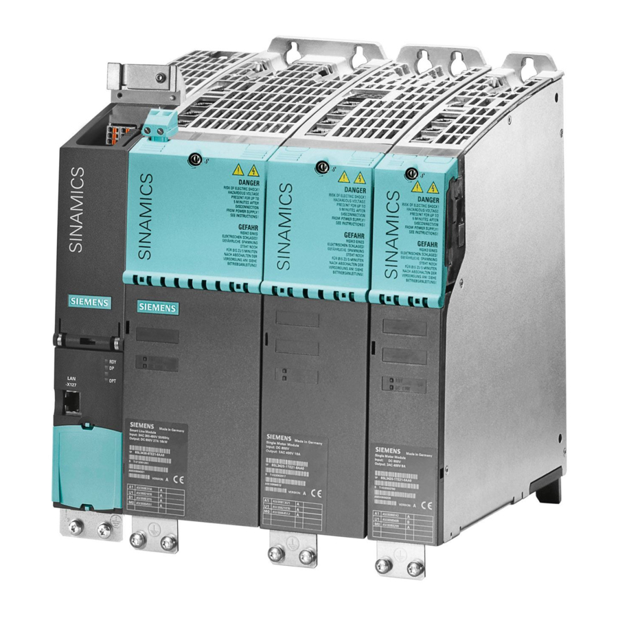
Page 45: Control Units And Operating Elements
Control Units and operating elements Introduction Description Control Units CU320-2 PN and CU320-2 DP of the SINAMICS S system are designed for use with several drives. The number of variable-speed drives depends on: • The required performance • The required additional functions •... - Page 46 Control Units and operating elements 4.1 Introduction ① Cover ② Blanking cover ③ Option Board (optional) ④ Memory card Figure 4-1 Overview, Control Unit CU320-2 PN Control Units and additional system components Equipment Manual, 06/2020, 6SL3097-5AH00-0BP2...
- Page 47 Control Units and operating elements 4.1 Introduction ① Cover ② Blanking cover ③ Option Board (optional) ④ Memory card Figure 4-2 Overview, Control Unit CU320-2 DP Note The Control Unit, the option board, and the memory card must be ordered separately. If your application requires more than one Control Unit, the number can be increased accordingly.
-
Page 48: Safety Instructions For Control Units
Control Units and operating elements 4.2 Safety instructions for Control Units Control PROFIBUS Active Active Single Single Single Single Line Line Motor Motor Motor Motor Module Module Module Module Module Module DRIVE-CLiQ DRIVE-CLiQ Figure 4-3 Sample configuration Safety instructions for Control Units NOTICE Component destruction as a result of high leakage currents The Control Unit or other PROFIBUS and/or PROFINET nodes can be destroyed if significant... -
Page 49: Control Unit Cu320-2 Pn (Profinet)
Damage through use of incorrect DRIVE-CLiQ cables The use of incorrect or unreleased DRIVE-CLiQ cables can cause damage or functional faults to devices or the system. • Only use suitable DRIVE-CLiQ cables that have been released by Siemens for the particular application. Note Malfunctions due to polluted DRIVE-CLiQ interfaces Malfunctions can occur in the system through the use of polluted DRIVE-CLiQ interfaces. - Page 50 Control Units and operating elements 4.3 Control Unit CU320-2 PN (PROFINET) The CU320-2 PN has the following interfaces (ports): Table 4-1 Overview of the CU320-2 PN interfaces Type Quantity Isolated digital inputs Non-isolated digital inputs/outputs DRIVE-CLiQ interfaces PROFINET interfaces LAN (Ethernet) Serial interface (RS232) Option slot Measuring terminals...
-
Page 51: Interface Description
Control Units and operating elements 4.3 Control Unit CU320-2 PN (PROFINET) 4.3.2 Interface description 4.3.2.1 Overview Figure 4-4 Interface overview CU320-2 PN (without cover and blanking cover) Control Units and additional system components Equipment Manual, 06/2020, 6SL3097-5AH00-0BP2... - Page 52 Control Units and operating elements 4.3 Control Unit CU320-2 PN (PROFINET) Figure 4-5 Interface X140 and measuring socket - CU320-2 PN (view from below) Control Units and additional system components Equipment Manual, 06/2020, 6SL3097-5AH00-0BP2...
-
Page 53: X100-X103 Drive-Cliq Interfaces
Control Units and operating elements 4.3 Control Unit CU320-2 PN (PROFINET) Measuring socket PCB connector Figure 4-6 Mounting a PC board connector (Phoenix Contact) in the measuring socket 4.3.2.2 X100-X103 DRIVE-CLiQ interfaces Table 4-2 X100-X103 DRIVE-CLiQ interfaces Signal name Technical data Transmit data + Transmit data - Receive data +... -
Page 54: X122 Digital Inputs/Outputs
Control Units and operating elements 4.3 Control Unit CU320-2 PN (PROFINET) 4.3.2.3 X122 digital inputs/outputs Table 4-3 X122 digital inputs/outputs Terminal Designation Technical data DI 0 Voltage: -3 … +30 V DC Electrical isolation: Yes DI 1 Reference potential: M1 DI 2 Input characteristic acc. - Page 55 Control Units and operating elements 4.3 Control Unit CU320-2 PN (PROFINET) Terminal Designation Technical data Switching frequency for ohmic load: Max. 100 Hz For inductive load: Max. 0.5 Hz For lamp load: max. 10 Hz Lamp load: max. 5 W Type: Spring-loaded terminal 3 (Page 320) DI: digital input;...
-
Page 56: X132 Digital Inputs/Outputs
Control Units and operating elements 4.3 Control Unit CU320-2 PN (PROFINET) 4.3.2.4 X132 digital inputs/outputs Table 4-4 X132 digital inputs/outputs Terminal Designation Technical data DI 4 Voltage: -3 … +30 V DC Electrical isolation: Yes DI 5 Reference potential: M2 DI 6 Input characteristic acc. -
Page 57: X124 Electronics Power Supply
Control Units and operating elements 4.3 Control Unit CU320-2 PN (PROFINET) Terminal Designation Technical data Switching frequency for ohmic load: Max. 100 Hz For inductive load: Max. 0.5 Hz For lamp load: max. 10 Hz Lamp load: max. 5 W Type: Spring-loaded terminal 3 (Page 320) DI: digital input;... -
Page 58: X127 Lan (Ethernet)
Control Units and operating elements 4.3 Control Unit CU320-2 PN (PROFINET) The maximum cable length that can be connected is 30 m. Note The two "+" or "M" terminals are jumpered in the connector. This ensures that the supply voltage is looped through. -
Page 59: X140 Serial Interface (Rs 232)
Control Units and operating elements 4.3 Control Unit CU320-2 PN (PROFINET) For diagnostic purposes, the X127 LAN interface features a green and a yellow LED. These LEDs indicate the following status information: Table 4-7 LED statuses for the X127 LAN interface Color Status Description... -
Page 60: X150 P1/P2 Profinet
Control Units and operating elements 4.3 Control Unit CU320-2 PN (PROFINET) 4.3.2.8 X150 P1/P2 PROFINET The PROFINET interfaces can be operated isochronously. Table 4-9 X150 P1 and X150 P2 PROFINET Signal name Technical data Receive data + Receive data - Transmit data + Reserved, do not use Reserved, do not use... -
Page 61: Buttons
Control Units and operating elements 4.3 Control Unit CU320-2 PN (PROFINET) Note Cable cross section The measuring terminals are only suitable for conductor cross-sections of 0.2 mm up to 1 mm Note Use of the measuring socket The measuring socket supports commissioning and diagnostic functions. It must not be connected for normal operation. - Page 62 • Do not return the memory card as well, but keep it in a safe place so that it can be inserted in the replacement unit. Note Please note that only SIEMENS memory cards can be used to operate the Control Unit. Control Units and additional system components Equipment Manual, 06/2020, 6SL3097-5AH00-0BP2...
-
Page 63: Connection Example
Control Units and operating elements 4.3 Control Unit CU320-2 PN (PROFINET) 4.3.3 Connection example Figure 4-8 Connection example of a Control Unit CU320-2 PN Control Units and additional system components Equipment Manual, 06/2020, 6SL3097-5AH00-0BP2... -
Page 64: Meaning Of Leds
Control Units and operating elements 4.3 Control Unit CU320-2 PN (PROFINET) 4.3.4 Meaning of LEDs 4.3.4.1 Description of the LED statuses The different states during power-up and in operation are indicated by the LEDs on the Control Unit. • The duration of the individual statuses varies. •... -
Page 65: Behavior Of The Leds In The Operating State
2 Hz Flashing PROFIenergy energy saving mode is active – light For more detailed information see Function Manual 0.5 s on "SINAMICS S120 Drive Functions". 3 s off Flashing General error Check parameterization / con‐ light figuration 2 Hz... - Page 66 DCP = Discovery and Configuration Protocol DCP is used by PROFINET to determine PROFINET devices and allow basic settings. Further information can be found in the SINAMICS S120 Function Manual "Communication". Any individual behaviors of the LED OPT are described for the respective Option Board.
-
Page 67: Dimension Drawing
Control Units and operating elements 4.3 Control Unit CU320-2 PN (PROFINET) 4.3.5 Dimension drawing 49,5 (1.95) (0.97) 223,5 (8.80) Figure 4-9 Dimension drawing of CU320-2 PN, all data in mm and (inches) 4.3.6 Technical data Table 4-15 Technical data 6SL3040-1MA01-0AA0 Unit Value Electronics power supply... -
Page 68: Control Unit Cu320-2 Dp (Profibus)
Response time The response time of digital inputs/outputs depends on the evaluation (refer to the function diagram). More information is provided in the following reference: Reference: SINAMICS S120/S150 List Manual, Chapter "Func‐ tion diagrams/CU320-2 input/output terminals" Ventilation clearances, above/below Weight Control Unit CU320-2 DP (PROFIBUS) 4.4.1... -
Page 69: Interface Description
Control Units and operating elements 4.4 Control Unit CU320-2 DP (PROFIBUS) 4.4.2 Interface description 4.4.2.1 Overview Figure 4-10 Interface overview CU320-2 DP (without cover and blanking cover) Control Units and additional system components Equipment Manual, 06/2020, 6SL3097-5AH00-0BP2... - Page 70 Control Units and operating elements 4.4 Control Unit CU320-2 DP (PROFIBUS) Figure 4-11 Interface X140 and measuring sockets T0 to T2 - CU320-2 DP (view from below) Control Units and additional system components Equipment Manual, 06/2020, 6SL3097-5AH00-0BP2...
-
Page 71: X100-X103 Drive-Cliq Interfaces
Control Units and operating elements 4.4 Control Unit CU320-2 DP (PROFIBUS) Measuring socket PCB connector Figure 4-12 Mounting a PC board connector (Phoenix Contact) in the measuring socket 4.4.2.2 X100-X103 DRIVE-CLiQ interfaces Table 4-17 X100-X103 DRIVE-CLiQ interfaces Signal name Technical data Transmit data + Transmit data - Receive data +... -
Page 72: X122 Digital Inputs/Outputs
Control Units and operating elements 4.4 Control Unit CU320-2 DP (PROFIBUS) 4.4.2.3 X122 digital inputs/outputs Table 4-18 X122 digital inputs/outputs Terminal Designation Technical data DI 0 Voltage: -3 … +30 V DC Electrical isolation: Yes DI 1 Reference potential: M1 DI 2 Input characteristic acc. - Page 73 Control Units and operating elements 4.4 Control Unit CU320-2 DP (PROFIBUS) Terminal Designation Technical data Switching frequency for ohmic load: Max. 100 Hz For inductive load: Max. 0.5 Hz For lamp load: max. 10 Hz Lamp load: max. 5 W Type: Spring-loaded terminal 3 (Page 320) DI: digital input;...
-
Page 74: X132 Digital Inputs/Outputs
Control Units and operating elements 4.4 Control Unit CU320-2 DP (PROFIBUS) 4.4.2.4 X132 digital inputs/outputs Table 4-19 X132 digital inputs/outputs Terminal Designation Technical data DI 4 Voltage: -3 … +30 V DC Electrical isolation: Yes DI 5 Reference potential: M2 DI 6 Input characteristic acc. -
Page 75: X124 Electronics Power Supply
Control Units and operating elements 4.4 Control Unit CU320-2 DP (PROFIBUS) Terminal Designation Technical data Switching frequency for ohmic load: Max. 100 Hz For inductive load: Max. 0.5 Hz For lamp load: max. 10 Hz Lamp load: max. 5 W Type: Spring-loaded terminal 3 (Page 320) DI: digital input;... -
Page 76: X126 Profibus
Control Units and operating elements 4.4 Control Unit CU320-2 DP (PROFIBUS) The maximum cable length that can be connected is 30 m. Note The two "+" or "M" terminals are jumpered in the connector. This ensures that the supply voltage is looped through. -
Page 77: Setting The Profibus Address
Control Units and operating elements 4.4 Control Unit CU320-2 DP (PROFIBUS) 4.4.2.7 Setting the PROFIBUS address On the CU320-2 DP, the PROFIBUS address is set as a hexadecimal value via two rotary coding switches. You can set values from 0 ) to 127 ). -
Page 78: X127 Lan (Ethernet)
– The address is set manually to values from 1 to 126 using the rotary coding switches. In this case, parameter p0918 is only used to read the address. More information Further information for setting the PROFIBUS address is available in the SINAMICS S120 Function Manual "Drive Functions". 4.4.2.8... -
Page 79: X140 Serial Interface (Rs 232)
Control Units and operating elements 4.4 Control Unit CU320-2 DP (PROFIBUS) Note The LAN interface does not support auto-MDI(X). If the LAN interface of the communication partner also cannot handle auto-MDI(X), then a crossover cable must be used to establish the connection. -
Page 80: Measuring Socket
Control Units and operating elements 4.4 Control Unit CU320-2 DP (PROFIBUS) 4.4.2.10 Measuring socket Table 4-26 Measuring socket with mounted PC board connector Socket Function Technical data Ground Voltage: 0… 5 V Resolution: 8 bits Measuring terminal 0 Load current: max. 3 mA Measuring terminal 1 Continuous short-circuit proof Measuring terminal 2... -
Page 81: Slot For Memory Card
Control Units and operating elements 4.4 Control Unit CU320-2 DP (PROFIBUS) 4.4.2.12 Slot for memory card Figure 4-13 Slot for memory card Note Plant standstill by withdrawing or inserting the memory card during operation If the memory card is withdrawn or inserted during operation, then data can be lost, possibly resulting in a plant standstill. - Page 82 • Do not return the memory card as well, but keep it in a safe place so that it can be inserted in the replacement unit. Note Please note that only SIEMENS memory cards can be used to operate the Control Unit. Control Units and additional system components Equipment Manual, 06/2020, 6SL3097-5AH00-0BP2...
-
Page 83: Connection Example
Control Units and operating elements 4.4 Control Unit CU320-2 DP (PROFIBUS) 4.4.3 Connection example Figure 4-14 Connection example of CU320-2 DP Control Units and additional system components Equipment Manual, 06/2020, 6SL3097-5AH00-0BP2... -
Page 84: Meaning Of The Leds
Control Units and operating elements 4.4 Control Unit CU320-2 DP (PROFIBUS) 4.4.4 Meaning of the LEDs 4.4.4.1 Description of the LED statuses The different states during power-up and in operation are indicated by the LEDs on the Control Unit. • The duration of the individual statuses varies. •... -
Page 85: Behavior Of The Leds In The Operating State
Only active if a CBE20 Communication Board is in‐ – light serted: 0.5 s on PROFIenergy energy saving mode is active 3 s off For more detailed information see Function Manual "SINAMICS S120 Drive Functions". Flashing General error Check parameterization / con‐ light figuration data 2 Hz Red/ Flashing Control Unit is ready for operation. - Page 86 DCP is used by PROFINET to determine PROFINET devices and allow basic settings. Therefore this function is only available on the CU320-2 DP if the CBE20 Option Board is inserted. Further information can be found in the SINAMICS S120 Function Manual "Communication". Any individual behaviors of the LED OPT are described for the respective Option Board.
-
Page 87: Dimension Drawing
Control Units and operating elements 4.4 Control Unit CU320-2 DP (PROFIBUS) 4.4.5 Dimension drawing 49,5 (1.95) (0.97) 223,5 (8.80) Figure 4-15 Dimension drawing of CU320-2 DP, all data in mm and (inches) 4.4.6 Technical data Table 4-30 Technical data 6SL3040-1MA00-0AA0 Unit Value Electronics power supply... -
Page 88: Mounting Control Units
Response time The response time of digital inputs/outputs depends on the evaluation (refer to the function diagram). More information is provided in the following reference: Reference: SINAMICS S120/S150 List Manual, Chapter "Func‐ tion diagrams/CU320-2 input/output terminals" Ventilation clearances, above/below Weight Mounting Control Units 4.5.1... - Page 89 Control Units and operating elements 4.5 Mounting Control Units Then mount the Control Unit onto the Line Module as shown below. Table 4-32 Installing the Control Unit on a Line Module using the CU320-2 DP as an example 1. Mount the Control Unit onto the 2.
-
Page 90: Mounting On The Mounting Surface
Control Units and operating elements 4.5 Mounting Control Units 4.5.2 Mounting on the mounting surface Mounting a CU320-2 Control Unit directly onto a mounting surface Mount the fixing lug of the Control Unit on the mounting surface using M6 screws. Tightening torque: 6 Nm (53.1 lbf in) Mounting a CU320-2 Control Unit to a mounting surface using spacers To increase the overall depth of the Control Unit to the 270 mm overall depth of a booksize Line... -
Page 91: Opening And Removing The Cover
Control Units and operating elements 4.5 Mounting Control Units 4.5.3 Opening and removing the cover Table 4-33 Opening and lifting the cover using the CU320-2 DP as an example Release the cover by gently pressing the Swivel the cover to the front to open it. Control Unit with cover open release lug. -
Page 92: Basic Operator Panel Bop20
Control Units and operating elements 4.6 Basic Operator Panel BOP20 Basic Operator Panel BOP20 4.6.1 Description The Basic Operator Panel BOP20 contains 6 keys and a backlit display unit. The BOP20 can be plugged onto a SINAMICS Control Unit and operated. The following functions are possible with the BOP: •... - Page 93 Control Units and operating elements 4.6 Basic Operator Panel BOP20 Table 4-35 Displays Display Meaning Top left The active drive object of the BOP is displayed here. 2 positions The displays and key operations always refer to this drive object. Is lit (bright) if the displayed drive is in the RUN state (in operation).
-
Page 94: Mounting At The Control Unit
The keys are dependent on the actual display and are used to raise or lower values. Lower Display and operator controls of the BOP20 Additional information on the displays and operator controls of the BOP20 is available in the SINAMICS S120 Function Manual "Drive Functions". 4.6.3 Mounting at the Control Unit NOTICE... -
Page 95: Removal
Control Units and operating elements 4.6 Basic Operator Panel BOP20 3. Press the latching cams on the BOP20 together, CU320-2 DP with BOP20 installed and push the BOP20 straight in until you hear it engage. 4.6.4 Removal Please note the following information when removing the BOP20 from the Control Unit: 1. - Page 96 Control Units and operating elements 4.6 Basic Operator Panel BOP20 Control Units and additional system components Equipment Manual, 06/2020, 6SL3097-5AH00-0BP2...
-
Page 97: Option Boards
The Communication Board is inserted into the option slot on a Control Unit. Were precise information on the function of the CBC10 can be taken from the following reference: References: SINAMICS S120 Commissioning Manual CANopen Interface Control Units and additional system components Equipment Manual, 06/2020, 6SL3097-5AH00-0BP2... -
Page 98: Interface Description
Option boards 5.3 CAN Communication Board CBC10 5.3.2 Interface description 5.3.2.1 Overview CBC10 X451 CAN socket X452 CAN pin Figure 5-1 Interface overview of the CBC10 Control Units and additional system components Equipment Manual, 06/2020, 6SL3097-5AH00-0BP2... -
Page 99: X451 Can Bus Interface
Option boards 5.3 CAN Communication Board CBC10 5.3.2.2 X451 CAN bus interface Table 5-2 X451: CAN bus interface Designation Technical data Reserved, do not use CAN_L CAN signal (dominant low) CAN_GND CAN ground Reserved, do not use CAN_SHLD Optional shield CAN ground CAN_H CAN signal... -
Page 100: 2-Pin Smd Dil Switch
Option boards 5.3 CAN Communication Board CBC10 5.3.2.4 2-pin SMD DIL switch ① Switch 1 ② Switch 2 Figure 5-2 2-pin SMD DIL switch 1 and 2 on the CBC10 Table 5-4 2-pin SMD DIL switch ID on the component Switch Function Switch position... -
Page 101: Meaning Of The Opt Led On The Control Unit
Double flash: The OPT LED OPT goes through the following states "on" (200 ms) – "off" (200 ms) – "on" (200 ms) – "off" (1000 ms) in one cycle. You will find more detailed information on the function of the CBC10 in the following reference: SINAMICS S120 CANopen Commissioning Manual. -
Page 102: Technical Data
Communication Board Ethernet CBE20 5.4.1 Description The SINAMICS S120 system can be connected to PROFINET via the Ethernet CBE20 Communication Board. The CBE20 supports PROFINET IO with Isochronous Realtime Ethernet (IRT) and PROFINET IO with RT. Control Units and additional system components... -
Page 103: Interface Description
Option boards 5.4 Communication Board Ethernet CBE20 The Communication Board has an Ethernet interface with 4 ports for communication. It is inserted into the option slot on a Control Unit. Note Only one communication interface can be used in isochronous operation when operating the Communication Board CBE20 in a Control Unit CU320-2. -
Page 104: X1400 Ethernet Interface
Option boards 5.4 Communication Board Ethernet CBE20 5.4.2.2 X1400 Ethernet interface Table 5-7 X1400: Ethernet, ports 1-4 Signal name Technical data Receive data + Receive data - Transmit data + Reserved, do not use Reserved, do not use Transmit data - Reserved, do not use Reserved, do not use Screened back‐... - Page 105 Option boards 5.4 Communication Board Ethernet CBE20 Table 5-9 Meaning of the Sync and Fault LEDs on the CBE20 Color Status Description Fault – If the link port LED is green: The CBE20 is operating error-free. Data is being exchanged with the configured IO con‐ troller.
-
Page 106: Installation
Option boards 5.4 Communication Board Ethernet CBE20 Table 5-10 Meaning of the OPT LED on the Control Unit Color Status Description, cause Remedy – The electronics power supply is missing or outside the permis‐ – sible tolerance range. CBE20 either defective or not inserted. Green Continu‐... -
Page 107: Technical Data
Option boards 5.5 Terminal Board TB30 ① Protective cover ② Option Board Figure 5-6 Installing the Option Board using a CU320-2 DP as an example 5.4.5 Technical data Table 5-11 Technical data Communication Board CBE20 Unit Value 6SL3055-0AA00-2EB. Max. current requirements (at 24 V DC) Power loss Weight <0.1... -
Page 108: Interface Description
Option boards 5.5 Terminal Board TB30 The TB30 Terminal Board has the following terminals: Table 5-12 Interface overview Type Quantity Digital inputs Digital outputs Analog inputs Analog outputs 5.5.2 Interface description 5.5.2.1 Overview TB30 X424 Power supply of digital outputs X481 Digital inputs/outputs X482... - Page 109 Option boards 5.5 Terminal Board TB30 The maximum cable length is 30 m. Note The two "+" or "M" terminals are jumpered in the connector. This ensures that the supply voltage is looped through. This power supply is required for the digital outputs only. The electronics power supply and the power supply for the analog inputs/outputs are taken from the option slot of the Control Unit.
-
Page 110: X481 Digital Inputs/Outputs
Option boards 5.5 Terminal Board TB30 5.5.2.3 X481 digital inputs/outputs Table 5-14 X481: Digital inputs/outputs Terminal Designation Technical data DI 0 Voltage: -3 … 30 V DC DI 1 Electrical isolation: Yes Reference potential: X424.M DI 2 Input characteristic acc. to IEC 61131-2, type 1 DI 3 Input voltage (including ripple) "1"... -
Page 111: X482 Analog Inputs/Outputs
Option boards 5.5 Terminal Board TB30 Note Malfunction in the switched-off state due to diagnostic currents Unlike mechanical switching contacts, e.g. emergency stop switches, diagnostic currents can also flow when the semiconductor is in the switched-off state (logical state "0" or "OFF"). If interconnection with digital inputs is faulty, the diagnostic currents can result in incorrect switching states. -
Page 112: Meaning Of The Opt Led On The Control Unit
Option boards 5.5 Terminal Board TB30 Connecting the analog inputs You can find more information about the analog inputs in the SINAMICS S120 Drive Functions Function Manual. 5.5.3 Meaning of the OPT LED on the Control Unit With inserted TB30 option board, the OPT LED has the standard meanings as described in the relevant chapters for the CU320-2 PN (PROFINET) (Page 63) or CU320-2 DP (PROFIBUS) (Page 83)Control Units. -
Page 113: Connection Example
Option boards 5.5 Terminal Board TB30 5.5.4 Connection example Figure 5-8 Connection example for TB30 5.5.5 Installation 1. Release the screws and remove the protective cover from the Control Unit. 2. Place the Option Board into the slot on the Control Unit and fix it in place using the screws. Screws: M3 Tool: Torx T10 screwdriver Tightening torque: 0.8 Nm (7.1 lbf in) -
Page 114: Shield Support
Option boards 5.5 Terminal Board TB30 ① Protective cover ② Option Board Figure 5-9 Installing an Option Board using a CU320-2 DP as an example 5.5.6 Shield support Figure 5-10 Shield support for TB30 on the CU320-2 DP The permissible bending radii for the cables must not be exceeded when the cables are being installed. -
Page 115: Technical Data
Response time The response time of the digital input/outputs and the analog inputs/outputs depends on the evaluation on the Control Unit (see function diagram). Additional information is available in the SINAMICS S120/ S150 List Manual, Chapter "Function Diagrams/Terminal Board TB30" Weight... - Page 116 Option boards 5.5 Terminal Board TB30 Control Units and additional system components Equipment Manual, 06/2020, 6SL3097-5AH00-0BP2...
-
Page 117: Terminal Modules
Terminal Modules Description Terminal Modules are terminal expansion modules for snapping onto a mounting rail according to EN 60715. Each of them has 2 DRIVE-CLiQ interfaces for communication with the Control Unit and an additional Terminal Module or Sensor Module. They have a 24 V DC power supply. Table 6-1 Terminal Modules for the CU320-2 Designation... -
Page 118: Safety Instructions For Terminal Modules
Damage through use of incorrect DRIVE-CLiQ cables The use of incorrect or unreleased DRIVE-CLiQ cables can cause damage or functional faults to devices or the system. • Only use suitable DRIVE-CLiQ cables that have been released by Siemens for the particular application. Note Malfunctions due to polluted DRIVE-CLiQ interfaces Malfunctions can occur in the system through the use of polluted DRIVE-CLiQ interfaces. -
Page 119: Terminal Module Tm15
Terminal Modules 6.3 Terminal Module TM15 Terminal Module TM15 6.3.1 Description The Terminal Module TM15 is a terminal expansion for snapping on to an EN 60715 DIN rail. The TM15 can be used to increase the number of available digital inputs/outputs within a drive system. -
Page 120: Interface Description
Terminal Modules 6.3 Terminal Module TM15 6.3.2 Interface description 6.3.2.1 Overview Figure 6-1 TM15 interface overview Control Units and additional system components Equipment Manual, 06/2020, 6SL3097-5AH00-0BP2... -
Page 121: X500/X501 Drive-Cliq Interfaces
Terminal Modules 6.3 Terminal Module TM15 6.3.2.2 X500/X501 DRIVE-CLiQ interfaces Table 6-3 X500/X501 DRIVE-CLiQ interfaces Signal name Technical data Transmit data + Transmit data - Receive data + Reserved, do not use Reserved, do not use Receive data - Reserved, do not use Reserved, do not use + (24 V) Power supply... -
Page 122: X520 Bidirectional Digital Inputs/Outputs
Terminal Modules 6.3 Terminal Module TM15 6.3.2.3 X520 bidirectional digital inputs/outputs Table 6-4 X520 digital inputs/outputs Terminal Designation Technical data See Chapter "Technical data (Page 128)". DI/DO 0 DI/DO 1 DI/DO 2 DI/DO 3 DI/DO 4 DI/DO 5 DI/DO 6 DI/DO 7 M1 (GND) Type: Screw terminal 1 (Page 321) -
Page 123: X522 Bidirectional Digital Inputs/Outputs
Terminal Modules 6.3 Terminal Module TM15 6.3.2.5 X522 bidirectional digital inputs/outputs Table 6-6 X522 digital inputs/outputs Terminal Designation Technical data See Chapter "Technical data (Page 128)". DI/DO 16 DI/DO 17 DI/DO 18 DI/DO 19 DI/DO 20 DI/DO 21 DI/DO 22 DI/DO 23 M3 (GND) Type: Screw terminal 1 (Page 321) -
Page 124: Connection Example
Terminal Modules 6.3 Terminal Module TM15 6.3.3 Connection example Figure 6-2 Example connection of TM15 Control Units and additional system components Equipment Manual, 06/2020, 6SL3097-5AH00-0BP2... -
Page 125: Meaning Of The Led
Terminal Modules 6.3 Terminal Module TM15 6.3.4 Meaning of the LED Table 6-8 Meanings of the LEDs on the Terminal Module TM15 Color Status Description, cause Remedy READY The electronics power supply is missing or outside the permis‐ – sible tolerance range. Green Continuous The component is ready for operation. -
Page 126: Dimension Drawing
Terminal Modules 6.3 Terminal Module TM15 6.3.5 Dimension drawing Figure 6-3 Dimension drawing of Terminal Module TM15, all data in mm and (inches) 6.3.6 Mounting Mounting 1. Tilt the component backwards slightly and attach it to the DIN rail using the hooks. 2. - Page 127 Terminal Modules 6.3 Terminal Module TM15 ① Mounting slide ② Mounting rail Figure 6-4 Removing from a DIN mounting rail Control Units and additional system components Equipment Manual, 06/2020, 6SL3097-5AH00-0BP2...
-
Page 128: Protective Conductor Connection And Shield Support
Terminal Modules 6.3 Terminal Module TM15 6.3.7 Protective conductor connection and shield support It is always advisable to shield the digital input/output wiring. The following diagram shows a typical Weidmüller shield connection clamp for the shield supports. ① Protective conductor connection M4 / 1.8 Nm (15.9 lbf in) ②... -
Page 129: Connector Coding
Terminal Modules 6.3 Terminal Module TM15 6.3.8 Connector coding A series of coding elements ("coding sliders") are supplied with each Terminal Module TM15. Connector coding 1. Insert at least one coding slider at the required position. 2. Remove the associated coding lug at the connector. ①... -
Page 130: Technical Data
Terminal Modules 6.3 Terminal Module TM15 6.3.9 Technical data Table 6-9 Technical data 6SL3055-0AA00-3FA. Unit Value Electronics power supply Voltage 24 (20.4 … 28.8) Current (without DRIVE-CLiQ or digital outputs) ≤0.15 Power loss ≤3 Max. cable length Digital inputs/outputs Can either be parameterized as DI or DO Number of digital inputs/outputs Electrical isolation Yes, in groups of 8... -
Page 131: Terminal Module Tm31
(approx. 1 DRIVE-CLiQ cycle). • Evaluation on the Control Unit (see function diagram) More information is provided in the following reference: Reference: SINAMICS S120/S150 List Manual, Chapter "Function dia‐ grams/Terminal Module 15" Protective ground conductor connection At the housing with M4 screw... -
Page 132: Interface Description
Terminal Modules 6.4 Terminal Module TM31 6.4.2 Interface description 6.4.2.1 Overview Figure 6-7 Interface overview TM31 Control Units and additional system components Equipment Manual, 06/2020, 6SL3097-5AH00-0BP2... -
Page 133: X500/X501 Drive-Cliq Interfaces
Terminal Modules 6.4 Terminal Module TM31 6.4.2.2 X500/X501 DRIVE-CLiQ interfaces Table 6-11 X500/X501 DRIVE-CLiQ interfaces Signal name Technical data Transmit data + Transmit data - Receive data + Reserved, do not use Reserved, do not use Receive data - Reserved, do not use Reserved, do not use + (24 V) Power supply... -
Page 134: X521 Analog Inputs
Terminal Modules 6.4 Terminal Module TM31 Note Ensuring the function of digital inputs An open input is interpreted as "low". Terminal M1 must be connected so that the digital inputs (DI) can function. This is achieved by using one of the following measures: 1. -
Page 135: S5 Current/Voltage Changeover Switch For Analog Inputs
Terminal Modules 6.4 Terminal Module TM31 Note The power supply for the analog inputs can be taken internally or from an external power supply unit 6.4.2.5 S5 current/voltage changeover switch for analog inputs Table 6-14 Current/voltage selector S5 Switch Function S5.0 Selector voltage (V)/current (I) Al0 S5.1... -
Page 136: X524 Electronics Power Supply
Terminal Modules 6.4 Terminal Module TM31 NOTICE Damage to motor in the event of incorrectly connected KTY temperature sensor If a KTY temperature sensor is connected with incorrect polarity, it is not possible to detect when the motor overheats. Overheating can cause damage to the motor. •... -
Page 137: X530 Digital Inputs
Terminal Modules 6.4 Terminal Module TM31 6.4.2.8 X530 digital inputs Table 6-17 X530: Digital inputs Terminal Designation Technical data DI 4 Voltage: -3 … +30 V DC DI 5 Electrical isolation: Yes Reference potential: M2 DI 6 Input characteristic acc. to IEC 61131-2, type 1 DI 7 Input voltage (including ripple) "1"... - Page 138 Terminal Modules 6.4 Terminal Module TM31 Note This voltage supply is only for powering the digital inputs. Note If the 24 V supply is briefly interrupted, the auxiliary voltage for the digital inputs is deactivated for this time. Control Units and additional system components Equipment Manual, 06/2020, 6SL3097-5AH00-0BP2...
-
Page 139: X541 Bidirectional Digital Inputs/Outputs
Terminal Modules 6.4 Terminal Module TM31 6.4.2.10 X541 bidirectional digital inputs/outputs Table 6-19 X541: Bidirectional digital inputs/outputs Terminal Designation Technical data As input: DI/DO 11 Voltage: -3 … +30 V DC Electrical isolation: no DI/DO 10 Reference potential: M DI/DO 9 Input characteristic acc. -
Page 140: X542 Relay Outputs
Terminal Modules 6.4 Terminal Module TM31 Note An open input is interpreted as "low". Note If the 24 V supply is briefly interrupted, then the digital outputs are deactivated during this time. 6.4.2.11 X542 relay outputs Table 6-20 X542: Relay outputs Terminal Designation Technical data... -
Page 141: Connection Example
Terminal Modules 6.4 Terminal Module TM31 6.4.3 Connection example Figure 6-8 Connection example of TM31 Control Units and additional system components Equipment Manual, 06/2020, 6SL3097-5AH00-0BP2... -
Page 142: Meaning Of The Led
Terminal Modules 6.4 Terminal Module TM31 6.4.4 Meaning of the LED Table 6-21 Meanings of the LEDs on the Terminal Module TM31 Color Status Description, cause Remedy READY The electronics power supply is missing or outside the per‐ – missible tolerance range. Green Continuous The component is ready for operation. -
Page 143: Dimension Drawing
Terminal Modules 6.4 Terminal Module TM31 6.4.5 Dimension drawing 50 (1.97) 105 (4.13) 110 (4.33) 118 (4.65) Figure 6-9 Dimension drawing of Terminal Module TM31, all data in mm and (inches) Control Units and additional system components Equipment Manual, 06/2020, 6SL3097-5AH00-0BP2... -
Page 144: Installation
Terminal Modules 6.4 Terminal Module TM31 6.4.6 Installation Installation 1. Tilt the component backwards slightly and attach it to the DIN rail using the hooks. 2. Swivel the component onto the DIN rail until you hear the mounting slide at the rear latch into position. - Page 145 Terminal Modules 6.4 Terminal Module TM31 The following diagram shows a typical Weidmüller shield connection clamp for the shield supports. ① Shield connection terminal, Weidmüller company, type: KLBUE CO1, Article number: 1753311001 ② Protective conductor connection M4 / 1.8 Nm (15.9 lbf in) Figure 6-11 Protective conductor connection and shield support NOTICE...
-
Page 146: Connector Coding
Terminal Modules 6.4 Terminal Module TM31 6.4.8 Connector coding To ensure that identical connectors are assigned correctly on the TM31, the connecters are encoded as shown in the following diagram. Coded connectors Figure 6-12 Example of connector coding at the TM31 The bending radii of the cables must be taken into account (see description of MOTION- CONNECT). -
Page 147: Technical Data
• Evaluation on the Control Unit (see function diagram). More information is provided in the following reference: Reference: SINAMICS S120/S150 List Manual, Chapter "Function diagrams/Terminal Module 31". Protective ground conductor connection At the housing with M4 screw Maximum cable lengths:... -
Page 148: Interface Description
Terminal Modules 6.5 Terminal Module TM41 Type Quantity Analog inputs TTL encoder output 6.5.2 Interface description 6.5.2.1 Overview Figure 6-13 TM41 interface overview Control Units and additional system components Equipment Manual, 06/2020, 6SL3097-5AH00-0BP2... -
Page 149: X500/X501 Drive-Cliq Interfaces
Terminal Modules 6.5 Terminal Module TM41 6.5.2.2 X500/X501 DRIVE-CLiQ interfaces Table 6-24 X500/X501 DRIVE-CLiQ interfaces Signal name Technical data Transmit data + Transmit data - Receive data + Reserved, do not use Reserved, do not use Receive data - Reserved, do not use Reserved, do not use + (24 V) Power supply... - Page 150 Terminal Modules 6.5 Terminal Module TM41 Note The X520 encoder interface produces signals acc. to RS422 standard. RS422 is a technical standard for differential serial data transmission Differential signals A/A*, B/B*, and R/R* must not be operated "single-ended". Control Units and additional system components Equipment Manual, 06/2020, 6SL3097-5AH00-0BP2...
-
Page 151: X521 Bidirectional Digital Inputs/Outputs
Terminal Modules 6.5 Terminal Module TM41 6.5.2.4 X521 bidirectional digital inputs/outputs Table 6-26 X521: Digital inputs/outputs Terminal Designation Technical data DI/DO 0 As input: DI/DO 1 Voltage: -3 … 30 V DC Electrical isolation: no DI/DO 2 Reference potential: M DI/DO 3 Input characteristic acc. -
Page 152: X522 Isolated Digital Inputs
Terminal Modules 6.5 Terminal Module TM41 Note This power supply is only for supplying the digital inputs. Note An open input is interpreted as "low". Note If the 24 V supply is briefly interrupted, then the digital outputs are deactivated during this time. 6.5.2.5 X522 isolated digital inputs Table 6-27... -
Page 153: X523 Analog Input
Terminal Modules 6.5 Terminal Module TM41 6.5.2.6 X523 analog input Table 6-28 X523: Analog input Terminal Designation Technical data AI 0- Voltage: -10 … +10 V; > 100 kΩ AI 0+ Resolution: 12 bits + sign Reserved, do not use Type: Screw terminal 1 (Page 321) AI: analog input Note... -
Page 154: Connection Example
Terminal Modules 6.5 Terminal Module TM41 6.5.3 Connection example Figure 6-14 Sample connection of TM41 Control Units and additional system components Equipment Manual, 06/2020, 6SL3097-5AH00-0BP2... -
Page 155: Meaning Of The Leds
Terminal Modules 6.5 Terminal Module TM41 6.5.4 Meaning of the LEDs Table 6-30 Meaning of the LEDs on the Terminal Module TM41 Color Status Description, cause Remedy READY The electronics power supply is missing or outside the per‐ – missible tolerance range. Green Continuous The component is ready for operation. -
Page 156: Dimension Drawing
Terminal Modules 6.5 Terminal Module TM41 6.5.5 Dimension drawing Figure 6-15 Dimension drawing of Terminal Module TM41, all data in mm and (inches) Control Units and additional system components Equipment Manual, 06/2020, 6SL3097-5AH00-0BP2... -
Page 157: Installation
Terminal Modules 6.5 Terminal Module TM41 6.5.6 Installation Installation 1. Tilt the component backwards slightly and attach it to the DIN rail using the hooks. 2. Swivel the component onto the DIN rail until you hear the mounting slide at the rear latch into position. - Page 158 Terminal Modules 6.5 Terminal Module TM41 The following diagram shows a typical Weidmüller shield connection clamp for the shield supports. ① Shield connection terminal, Weidmüller company, type: KLBUE CO1, Article number: 1753311001 ② Protective conductor connection M4 / 1.8 Nm (15.9 lbf in) Figure 6-17 Protective conductor connection and shield support The bending radii of the cables must be taken into account (see description of MOTION-...
-
Page 159: Technical Data
• Evaluation on the Control Unit (see function diagram). More information is provided in the following reference: Reference: SINAMICS S120/S150 List Manual, Chapter "Function diagrams/Terminal Module 41" Protective ground conductor connection At the housing with M4 screw Maximum cable lengths:... - Page 160 Terminal Modules 6.6 Terminal Module TM54F TM54F features the following interfaces: Table 6-32 Interface overview of the TM54F Type Quantity DRIVE-CLiQ interfaces Fail-safe digital inputs (F-DI) Fail-safe digital outputs (F-DO) Sensor power supplies, dynamization supported Sensor power supply, no dynamization Digital inputs to check F_DO for a test stop Power supply Sensors: Fail-safe devices to issue commands and sense - for example, emergency stop buttons and...
-
Page 161: Interface Description
Terminal Modules 6.6 Terminal Module TM54F 6.6.2 Interface description 6.6.2.1 Overview... -
Page 162: X500/X501 Drive-Cliq Interfaces
Terminal Modules 6.6 Terminal Module TM54F 6.6.2.2 X500/X501 DRIVE-CLiQ interfaces Table 6-33 X500/X501 DRIVE-CLiQ interfaces Signal name Technical data Transmit data + Transmit data - Receive data + Reserved, do not use Reserved, do not use Receive data - Reserved, do not use Reserved, do not use + (24 V) Power supply... -
Page 163: X520 Sensor Power Supply
Terminal Modules 6.6 Terminal Module TM54F 6.6.2.4 X520 sensor power supply Table 6-35 X520: Sensor power supply Terminal Designation Technical data Voltage: +24 V DC Max. total load current: 500 mA Without forced dormant error detection 6.6.2.5 X521 fail-safe digital inputs and dynamically adjustable power supply Table 6-36 X521: Fail-safe digital inputs Terminal... -
Page 164: X522 Fail-Safe Digital Inputs
Terminal Modules 6.6 Terminal Module TM54F Note Ensuring the function of digital inputs For the digital inputs DIx+ to function, the reference potential must be connected to input DIx- in each case. This is achieved by using one of the following measures: 1. - Page 165 Terminal Modules 6.6 Terminal Module TM54F Note Ensuring the function of digital inputs For the digital inputs DIx+ to function, the reference potential must be connected to input DIx- in each case. This is achieved by using one of the following measures: 1.
-
Page 166: X523 Fail-Safe Digital Output
Terminal Modules 6.6 Terminal Module TM54F 6.6.2.7 X523 fail-safe digital output Table 6-38 X523: Fail-safe digital output Terminal Designation Technical data DI 20 Voltage: -3 … +30 V DC Electrical isolation: Yes Reference potential: M1 Input characteristic acc. to IEC 61131-2, type 1 Input voltage (including ripple) "1"... -
Page 167: X524 Electronics Power Supply
Terminal Modules 6.6 Terminal Module TM54F 6.6.2.8 X524 electronics power supply Table 6-39 X524 electronics power supply Terminal Designation Technical data Electronics power supply (24 V) Voltage: 24 V DC (20.4 ... 28.8 V) Current consumption: max. 0.7 A Electronics power supply (24 V) (including DRIVE-CLiQ) Electronics ground (0 V) Max. -
Page 168: X525 Fail-Safe Digital Output
Terminal Modules 6.6 Terminal Module TM54F 6.6.2.9 X525 fail-safe digital output Table 6-40 X525: Fail-safe digital output Terminal Designation Technical data DI 21 Voltage: -3 … +30 V DC Electrical isolation: Yes Reference potential: M1 Input characteristic acc. to IEC 61131-2, type 1 Input voltage (including ripple) "1"... -
Page 169: X531 Fail-Safe Digital Inputs And Dynamically Adjustable Power Supply
Terminal Modules 6.6 Terminal Module TM54F 6.6.2.10 X531 fail-safe digital inputs and dynamically adjustable power supply Table 6-41 X531: Fail-safe digital inputs Terminal Designation Technical data Switched voltage: +24 V DC Max. total load current: 500 mA (voltage is switched for a test stop) DI 10 F-DI 5 Voltage: -3 …... -
Page 170: X532 Fail-Safe Digital Inputs
Terminal Modules 6.6 Terminal Module TM54F 6.6.2.11 X532 fail-safe digital inputs Table 6-42 X532: Fail-safe digital inputs Terminal Designation Technical data DI 14 F-DI 7 Voltage: -3 … +30 V DC DI 15+ Electrical isolation: Yes Reference potential: see terminals 7, 8, 9, 10 DI 16 F-DI 8 Input characteristic acc. -
Page 171: X533 Fail-Safe Digital Output
Terminal Modules 6.6 Terminal Module TM54F 6.6.2.12 X533 fail-safe digital output Table 6-43 X533: Fail-safe digital output Terminal Designation Technical data DI 22 Voltage: -3 … +30 V DC Electrical isolation: Yes Reference potential: M1 Input characteristic acc. to IEC 61131-2, type 1 Input voltage (including ripple) "1"... -
Page 172: X535 Fail-Safe Digital Output
Terminal Modules 6.6 Terminal Module TM54F 6.6.2.13 X535 fail-safe digital output Table 6-44 X535: Fail-safe digital output Terminal Designation Technical data DI 23 Voltage: -3 … +30 V DC Electrical isolation: Yes Reference potential: M1 Input characteristic acc. to IEC 61131-2, type 1 Input voltage (including ripple) "1"... -
Page 173: Connection Example
Terminal Modules 6.6 Terminal Module TM54F 6.6.3 Connection example Figure 6-19 Connection example off TM54F Control Units and additional system components Equipment Manual, 06/2020, 6SL3097-5AH00-0BP2... -
Page 174: Meaning Of The Leds
Terminal Modules 6.6 Terminal Module TM54F 6.6.4 Meaning of the LEDs Table 6-45 Meaning of the LEDs on the Terminal Module TM54F Color Status Description, cause Remedy READY The electronics power supply is missing or outside the – permissible tolerance range. Green Continuous The component is ready for operation, cyclic DRIVE-CLiQ... - Page 175 Terminal Modules 6.6 Terminal Module TM54F Color Status Description, cause Remedy F_DI z – (input x, (x – – NC contact/NC contact : (z = 0 … 9, x = 0, 2, … 18) +1)+, (x – Continuous Different signal states at input x and x+1 –...
-
Page 176: Dimension Drawing
Terminal Modules 6.6 Terminal Module TM54F 6.6.5 Dimension drawing 50 (1.97) 105 (4.13) 110 (4.33) 124 (4.88) Figure 6-20 Dimension drawing of Terminal Module TM54F, all data in mm and (inches) Control Units and additional system components Equipment Manual, 06/2020, 6SL3097-5AH00-0BP2... -
Page 177: Installation
Terminal Modules 6.6 Terminal Module TM54F 6.6.6 Installation Installation 1. Tilt the component backwards slightly and attach it to the DIN rail using the hooks. 2. Swivel the component onto the DIN rail until you hear the mounting slide at the rear latch into position. -
Page 178: Protective Conductor Connection And Shield Support
Terminal Modules 6.6 Terminal Module TM54F 6.6.7 Protective conductor connection and shield support It is always advisable to shield the digital input and output wiring. The following diagram shows a typical Weidmüller shield connection clamp for the shield support. ① Shield connection terminal, Weidmüller company, type: KLBUE CO1, Article number: 1753311001 ②... -
Page 179: Terminal Module Tm120
Terminal Modules 6.7 Terminal Module TM120 6SL3055-0AA00-3BA. Unit Value Max. load current per output Max. cable length for the 24 V infeed Power loss 4.5 at 24 V Protective ground conductor connection On the housing with M4 screw Ventilation clearances, above/below Weight Approx. -
Page 180: Interface Description
Terminal Modules 6.7 Terminal Module TM120 6.7.2 Interface description 6.7.2.1 Overview Figure 6-23 Interface overview TM120 Control Units and additional system components Equipment Manual, 06/2020, 6SL3097-5AH00-0BP2... -
Page 181: X500/X501 Drive-Cliq Interfaces
Terminal Modules 6.7 Terminal Module TM120 6.7.2.2 X500/X501 DRIVE-CLiQ interfaces Table 6-48 X500/X501: DRIVE-CLiQ interfaces Signal name Technical data Transmit data + Transmit data - Receive data + Reserved, do not use Reserved, do not use Receive data - Reserved, do not use Reserved, do not use + (24 V) Power supply... - Page 182 Terminal Modules 6.7 Terminal Module TM120 NOTICE Damage when using a non-specified temperature sensor If sensors other than those specified are connected, this may result in incorrect measured values. Damage can result if overheating is not detected. • Only connect temperature sensors that have been specified for operation with a TM120 Terminal Module.
-
Page 183: X524 Electronics Power Supply
Terminal Modules 6.7 Terminal Module TM120 Note A 6FX7008-1BC.1 power cable is recommended for connecting Pt1000 / KTY temperature sensors. Note The maximum length of the temperature sensor cable is 100 m. The cables must be shielded. 6.7.2.4 X524 Electronics power supply Table 6-51 X524 electronics power supply Terminal Designation... -
Page 184: Connection Examples
Terminal Modules 6.7 Terminal Module TM120 6.7.3 Connection examples Each TM120 is directly connected to an encoder evaluation unit (SMCxx or SMExx) by looping the corresponding DRIVE-CLiQ channel via the TM120. This ensures that encoders are automatically assigned to the temperature signals and, consequently, to the correct axis. The assignment can also be performed manually. -
Page 185: Meaning Of The Led
Terminal Modules 6.7 Terminal Module TM120 Figure 6-25 Connection example of TM120 with Motor Module and SMC20 (encoder evaluation) 6.7.4 Meaning of the LED Table 6-52 Meaning of the LEDs on the Terminal Module TM120 Color Status Description, cause Remedy READY The electronics power supply is missing or outside the permis‐... -
Page 186: Dimension Drawing
Terminal Modules 6.7 Terminal Module TM120 6.7.5 Dimension drawing (1.18) 105 (4.13) 111 (4.37) 130 (5.12) Figure 6-26 Dimension drawing of Terminal Module TM120, all data in mm and (inches) 6.7.6 Installation Installation 1. Tilt the component backwards slightly and attach it to the DIN rail using the hooks. 2. - Page 187 Terminal Modules 6.7 Terminal Module TM120 Removal 1. First shift the mounting slide downwards at the lug to release the interlocking with the mounting rail. 2. Swivel the component to the front and withdraw it upwards from the DIN rail. ①...
-
Page 188: Protective Conductor Connection And Shield Support
Terminal Modules 6.7 Terminal Module TM120 6.7.7 Protective conductor connection and shield support The following diagram shows a typical Weidmüller shield connection clamp for the shield supports. ① Shield connection terminal, Weidmüller company, type: KLBUE CO1, Article number: 1753311001 ② Protective conductor connection M4 / 1.8 Nm (15.9 lbf in) Figure 6-28 Protective conductor connection and shield support... -
Page 189: Terminal Module Tm150
Terminal Modules 6.8 Terminal Module TM150 Terminal Module TM150 6.8.1 Description The terminal module TM150 is a DRIVE-CLiQ component for temperature evaluation. The temperature is measured in a temperature range from -99 °C to +250 °C for the following temperature sensors: •... -
Page 190: Interface Description
Terminal Modules 6.8 Terminal Module TM150 6.8.2 Interface description 6.8.2.1 Overview Figure 6-29 Interface overview of Terminal Module TM150 Control Units and additional system components Equipment Manual, 06/2020, 6SL3097-5AH00-0BP2... -
Page 191: X500/X501 Drive-Cliq Interfaces
Terminal Modules 6.8 Terminal Module TM150 6.8.2.2 X500/X501 DRIVE-CLiQ interfaces Table 6-55 X500/X501: DRIVE-CLiQ interfaces Signal name Technical data Transmit data + Transmit data - Receive data + Reserved, do not use Reserved, do not use Receive data - Reserved, do not use Reserved, do not use + (24 V) Power supply, max. -
Page 192: X531-X536 Temperature Sensor Inputs
Terminal Modules 6.8 Terminal Module TM150 6.8.2.4 X531-X536 temperature sensor inputs Table 6-57 X531-X536: Temperature sensor inputs Terminal Function Function Technical data 1x2- / 2x2-wire 3 and 4-wire +Temp Temperature sensor connection for sensors with (channel x) (Channel x) 1x2 wires Connection of the 2nd measurement cable for sensors with 4 wires -Temp... - Page 193 Terminal Modules 6.8 Terminal Module TM150 NOTICE Overheating of the motor through jumpering the temperature sensor connections Jumpering temperature sensor connections "+Temp" and "-Temp" results in incorrect measurement results. Damage to the motor can result if the overheating is not detected. •...
-
Page 194: Connection Examples
Terminal Modules 6.8 Terminal Module TM150 6.8.3 Connection examples Figure 6-30 Connecting a Pt100/Pt1000 with 2x2, 3 and 4-wires to the temperature sensor inputs X53. of the TM150 Terminal Module Control Units and additional system components Equipment Manual, 06/2020, 6SL3097-5AH00-0BP2... - Page 195 Terminal Modules 6.8 Terminal Module TM150 Figure 6-31 Connection example for a Terminal Module TM150 Control Units and additional system components Equipment Manual, 06/2020, 6SL3097-5AH00-0BP2...
-
Page 196: Meaning Of The Led
Terminal Modules 6.8 Terminal Module TM150 6.8.4 Meaning of the LED Table 6-59 Meaning of the LEDs at the Terminal Module TM150 Color Status Description, cause Remedy READY – The electronics power supply is missing or outside the permis‐ Check the power sup‐ sible tolerance range. -
Page 197: Dimension Drawing
Terminal Modules 6.8 Terminal Module TM150 6.8.5 Dimension drawing Figure 6-32 Dimension drawing of Terminal Module TM150, all data in mm and (inches) Control Units and additional system components Equipment Manual, 06/2020, 6SL3097-5AH00-0BP2... -
Page 198: Installation
Terminal Modules 6.8 Terminal Module TM150 6.8.6 Installation Installation 1. Tilt the component backwards slightly and attach it to the DIN rail using the hooks. 2. Swivel the component onto the DIN rail until you hear the mounting slide at the rear latch into position. -
Page 199: Protective Conductor Connection And Shield Support
Terminal Modules 6.8 Terminal Module TM150 6.8.7 Protective conductor connection and shield support The following diagram shows a typical Weidmüller shield connection clamp for the shield supports. ① Shield connection terminal, Weidmüller company, type: KLBUE CO1, Article number: 1753311001 ② Protective conductor connection M4 / 1.8 Nm (15.9 lbf in) Figure 6-34 Protective conductor connection and shield support... - Page 200 Terminal Modules 6.8 Terminal Module TM150 Control Units and additional system components Equipment Manual, 06/2020, 6SL3097-5AH00-0BP2...
-
Page 201: Hub Modules
Damage through use of incorrect DRIVE-CLiQ cables The use of incorrect or unreleased DRIVE-CLiQ cables can cause damage or functional faults to devices or the system. • Only use suitable DRIVE-CLiQ cables that have been released by Siemens for the particular application. Note... -
Page 202: Drive-Cliq Hub Module Dmc20
Hub Modules 7.3 DRIVE-CLiQ Hub Module DMC20 DRIVE-CLiQ Hub Module DMC20 7.3.1 Description The DRIVE-CLiQ Hub Module DMC20 is an expansion module for snapping on to a standard mounting rail acc. to EN 60715. It is used to distribute a DRIVE-CLiQ line with a star-type topology. -
Page 203: X500-X505 Drive-Cliq Interfaces
Hub Modules 7.3 DRIVE-CLiQ Hub Module DMC20 7.3.2.2 X500-X505 DRIVE-CLiQ interfaces Table 7-2 X500-X505: DRIVE-CLiQ interfaces Signal name Technical data Transmit data + Transmit data - Receive data + Reserved, do not use Reserved, do not use Receive data - Reserved, do not use Reserved, do not use + (24 V) -
Page 204: Meaning Of The Led
Hub Modules 7.3 DRIVE-CLiQ Hub Module DMC20 7.3.3 Meaning of the LED Table 7-4 Description of the LEDs on the DRIVE-CLiQ Hub Module DMC20 Color Status Description, cause Remedy READY – The electronics power supply is missing or outside the permis‐ –... -
Page 205: Dimension Drawing
Hub Modules 7.3 DRIVE-CLiQ Hub Module DMC20 7.3.4 Dimension drawing 30 (1.18) 105 (4.13) 110 (4.33) Figure 7-2 Dimension drawing of the DRIVE-CLiQ Hub Module DMC20, all data in mm and (inches) 7.3.5 Installation Installation 1. Tilt the component backwards slightly and attach it to the DIN rail using the hooks. 2. - Page 206 Hub Modules 7.3 DRIVE-CLiQ Hub Module DMC20 Removal 1. First shift the mounting slide downwards at the lug to release the interlocking with the mounting rail. 2. Swivel the component to the front and withdraw it upwards from the DIN rail. ①...
-
Page 207: Protective Conductor Connection And Shield Support
Hub Modules 7.3 DRIVE-CLiQ Hub Module DMC20 7.3.6 Protective conductor connection and shield support The following diagram shows a typical Weidmüller shield connection clamp for the shield supports. ① Shield connection terminal, Weidmüller company, type: KLBUE CO1, Article number: 1753311001 ②... -
Page 208: Drive-Cliq Hub Module External Dme20
Hub Modules 7.4 DRIVE-CLiQ Hub Module External DME20 DRIVE-CLiQ Hub Module External DME20 7.4.1 Description The DRIVE-CLiQ Hub Module External DME20 is used to implement star-shaped distribution of a DRIVE-CLiQ line. With the DME20, an axis grouping can be expanded with 5 DRIVE-CLiQ sockets for additional subgroups. -
Page 209: Interface Description
Hub Modules 7.4 DRIVE-CLiQ Hub Module External DME20 7.4.2 Interface description 7.4.2.1 Overview X500, X501, X502, X503, X504, X505 DRIVE-CLiQ interfaces X524 24 V power supply Figure 7-5 Interface overview of the DME20 Control Units and additional system components Equipment Manual, 06/2020, 6SL3097-5AH00-0BP2... -
Page 210: X500-X505 Drive-Cliq Interfaces
Hub Modules 7.4 DRIVE-CLiQ Hub Module External DME20 7.4.2.2 X500-X505 DRIVE-CLiQ interfaces Table 7-6 X500-X505: DRIVE-CLiQ interfaces Signal name Technical data Transmit data + Transmit data - Receive data + Reserved, do not use Reserved, do not use Receive data - Reserved, do not use Reserved, do not use + (24 V) - Page 211 Hub Modules 7.4 DRIVE-CLiQ Hub Module External DME20 Where UL-compliant design is not required, use of the following cables and connectors from Siemens is recommended: Pre-assembled cables Connecting cable for power supply with M12 plug and M12 socket, A-coded, 4-pin, Article number: 6XV1801-5D..
-
Page 212: Dimension Drawing
Hub Modules 7.4 DRIVE-CLiQ Hub Module External DME20 7.4.3 Dimension drawing Figure 7-6 Dimension drawing of the DRIVE-CLiQ Hub Module External DME20, all data in mm and (inches) Control Units and additional system components Equipment Manual, 06/2020, 6SL3097-5AH00-0BP2... -
Page 213: Installation
Hub Modules 7.4 DRIVE-CLiQ Hub Module External DME20 7.4.4 Installation 87,5 (3.44) 99 (3.90) Ø5,3 (0.21) ① Contact surface Figure 7-7 Mounting dimensions DME20 Installation 1. Place the drilling pattern on the mounting surface. Make sure that the contact surface is bare, unpainted metal. -
Page 214: Specifications For Use With Ul Approval
Hub Modules 7.4 DRIVE-CLiQ Hub Module External DME20 7.4.6 Specifications for use with UL approval Pre-assembled cables Sensor/actuator cable, 5-pin, variable cable, free cable end at straight socket M12-SPEEDCON, cable length: 2, 5, 10, 15 m SAC-5P-...-186/FS SCO Up to 100 m on request Phoenix Contact Cables to be assembled by the user Cable... -
Page 215: Voltage Sensing Module Vsm10
Voltage Sensing Module VSM10 Description The Voltage Sensing Module VSM10 is an expansion module for snapping on to a standard mounting rail acc. to EN 60715. It is used to sense the actual value of a voltage. For example, it can be used to sense the three-phase line supply voltage, which is then provided to the closed- loop control. -
Page 216: Safety Instructions For The Voltage Sensing Module (Vsm10)
Damage through use of incorrect DRIVE-CLiQ cables The use of incorrect or unreleased DRIVE-CLiQ cables can cause damage or functional faults to devices or the system. • Only use suitable DRIVE-CLiQ cables that have been released by Siemens for the particular application. Note Malfunctions due to polluted DRIVE-CLiQ interfaces Malfunctions can occur in the system through the use of polluted DRIVE-CLiQ interfaces. -
Page 217: Interface Description
Voltage Sensing Module VSM10 8.3 Interface description Interface description 8.3.1 Overview... -
Page 218: X500 Drive-Cliq Interface
Voltage Sensing Module VSM10 8.3 Interface description PE conductor connection M4 / 1.8 Nm X530 Neutral point grounding Connector jumper Figure 8-2 X530 interface at the VSM10 (view from below) 8.3.2 X500 DRIVE-CLiQ interface Table 8-2 X500: DRIVE-CLiQ interface Signal name Technical data Transmit data + Transmit data -... -
Page 219: X520 Analog Inputs/Temperature Sensor
Voltage Sensing Module VSM10 8.3 Interface description 8.3.3 X520 analog inputs/temperature sensor Table 8-3 X520: Analog inputs/temperature sensor Terminal Designation Technical data AI 0- 2 analog differential inputs AI 0+ Voltage: -10 … +10 V; Ri > 100 kΩ Resolution: 12 bits + sign AI 1- AI 1+ + Temp... -
Page 220: X521 Three-Phase Voltage Sensing Up To 100 V 3-Ph. Ac
Voltage Sensing Module VSM10 8.3 Interface description WARNING Electric shock when the motor temperature sensor insulation fails When connecting temperature sensors, which have no safe protective separation with respect to the motor power circuit, then arcing to the signal electronics can occur. •... -
Page 221: X522 Three-Phase Voltage Sensing Up To 690 V 3-Ph. Ac
Voltage Sensing Module VSM10 8.3 Interface description 8.3.5 X522 three-phase voltage sensing up to 690 V 3-ph. AC Table 8-5 X522: Voltage sensing 690 V Terminal Designation Technical data Phase voltage U Directly connected to the line voltage sensing Phase voltage V Resistance to neutral point: ∼3500 kΩ... -
Page 222: X524 Electronics Power Supply
Voltage Sensing Module VSM10 8.3 Interface description 8.3.6 X524 Electronics power supply Table 8-6 X524: Electronics power supply Terminal Designation Technical data Electronics power supply (24 V) Voltage: 24 V DC (20.4 ... 28.8 V) Current consumption: max. 0.2 A Electronics power supply (24 V) Max. -
Page 223: Connection Example
Voltage Sensing Module VSM10 8.4 Connection example Connection example It is only possible to omit the fuses if the cables to the Voltage Sensing Module are routed so that no short-circuit or ground fault can be expected under normal operating conditions (short-circuit proof routing). Tap the line voltage as actual value for the Voltage Sensing Module VSM10 corresponding to the system design, for example refer to the table. -
Page 224: Meaning Of The Led
LED had during activation (setting of param‐ orange eter p0144 to "1"). Cause and rectification of faults Further information about the cause and rectification of faults is available in the SINAMICS S120 Function Manual "Drive Functions". Control Units and additional system components Equipment Manual, 06/2020, 6SL3097-5AH00-0BP2... -
Page 225: Dimension Drawing
Voltage Sensing Module VSM10 8.6 Dimension drawing Dimension drawing 50 (1.97) 105 (4.13) 110 (4.33) 134 (5.28) Figure 8-5 Dimension drawing of the Voltage Sensing Module VSM10, all data in mm and (inches) Control Units and additional system components Equipment Manual, 06/2020, 6SL3097-5AH00-0BP2... -
Page 226: Installation
Voltage Sensing Module VSM10 8.7 Installation Installation Installation 1. Tilt the component backwards slightly and attach it to the DIN rail using the hooks. 2. Swivel the component onto the DIN rail until you hear the mounting slide at the rear latch into position. -
Page 227: Protective Conductor Connection And Shield Support
Voltage Sensing Module VSM10 8.9 Operation on an isolated-neutral system (IT system) Protective conductor connection and shield support The following shield connection clamps can be used on the bottom part of the component housing for shield connection of the analog inputs: Shield connection clamp Article No. -
Page 228: Technical Data
Voltage Sensing Module VSM10 8.10 Technical data Use 2 screwdrivers or another suitable tool in order to relieve the strain on the holding springs in the terminal, and then withdraw the connector jumper. Terminal X530 with connector jumper Relieve the springs and withdraw the connector jumper WARNING Electric shock when the connector jumper is removed... -
Page 229: Service And Maintenance
Voltage Sensing Module VSM10 8.11 Service and maintenance 8.11 Service and maintenance Replacing the Voltage Sensing Module VSM10 in Smart Line Modules Chassis and Active Interface Modules Chassis When replacing a Voltage Sensing Module VSM10 in an Active Interface Module Chassis or Smart Line Module Chassis, observe the following application cases: 1. - Page 230 Voltage Sensing Module VSM10 8.11 Service and maintenance Control Units and additional system components Equipment Manual, 06/2020, 6SL3097-5AH00-0BP2...
-
Page 231: Encoder System Connection
Encoder system connection Introduction The encoder system should be connected to SINAMICS S120 via DRIVE-CLiQ. Motors with DRIVE-CLiQ interfaces (e.g. synchronous motors 1FK7 and 1FT7, and induction motors 1PH7 and 1PH8) are designed for this purpose. These motors simplify commissioning and diagnostics because the motor and encoder type are identified automatically. -
Page 232: Overview Of Sensor Modules
Encoder system connection 9.2 Overview of Sensor Modules Overview of Sensor Modules Sensor Modules Cabinet-Mounted (SMC) Sensor Modules Cabinet-Mounted SMC10, SMC20, SMC30 and SMC40 can be ordered and configured separately. They are used when a motor with a DRIVE-CLiQ interface is not available or when external encoders in addition to the motor encoder are required. - Page 233 Encoder system connection 9.2 Overview of Sensor Modules Direct encoder systems outside the cabinet can be connected to the Sensor Modules External. The Sensor Modules External evaluate these encoder systems and convert the calculated values to DRIVE-CLiQ. No motor or encoder data is stored in the Sensor Modules External. Note The Sensor Module External provides the encoder power supply.
-
Page 234: Safety Instructions For Sensor Modules And Encoders
Disconnecting or connecting plug-in connections during operation can damage devices or cause malfunctions. • Only disconnect or connect the encoder cables to Siemens motors in a voltage-free state if hot-plugging has not been specifically released. When using direct measuring systems (third-party encoders), ask the manufacturer whether it is permissible to disconnect/ connect under voltage. -
Page 235: Sensor Module Cabinet-Mounted Smc10
Damage through use of incorrect DRIVE-CLiQ cables The use of incorrect or unreleased DRIVE-CLiQ cables can cause damage or functional faults to devices or the system. • Only use suitable DRIVE-CLiQ cables that have been released by Siemens for the particular application. Note... -
Page 236: Interface Description
Encoder system connection 9.4 Sensor Module Cabinet-Mounted SMC10 9.4.2 Interface description 9.4.2.1 Overview Figure 9-3 Interface overview for the SMC10 Control Units and additional system components Equipment Manual, 06/2020, 6SL3097-5AH00-0BP2... -
Page 237: X500 Drive-Cliq Interface
Encoder system connection 9.4 Sensor Module Cabinet-Mounted SMC10 9.4.2.2 X500 DRIVE-CLiQ interface Table 9-2 X500: DRIVE-CLiQ interface Signal name Technical data Transmit data + Transmit data - Receive data + Reserved, do not use Reserved, do not use Receive data - Reserved, do not use Reserved, do not use Reserved, do not use... -
Page 238: X520 Encoder System Interface
Encoder system connection 9.4 Sensor Module Cabinet-Mounted SMC10 9.4.2.3 X520 encoder system interface Table 9-3 X520: Encoder system interface Signal name Technical data Reserved, do not use Reserved, do not use Resolver signal A (sin+) Inverted resolver signal A (sin-) Ground Ground (for internal shield) Resolver signal B (cos+) -
Page 239: X524 Electronics Power Supply
Encoder system connection 9.4 Sensor Module Cabinet-Mounted SMC10 Information for assigning parameters to the KTY temperature sensor can be found in the SINAMICS S120 Function Manual "Drive Functions" in the Chapter "Monitoring and protection functions/thermal motor protection". WARNING Electric shock when the motor temperature sensor insulation fails When connecting temperature sensors, which have no safe protective separation with respect to the motor power circuit, then arcing to the signal electronics can occur. -
Page 240: Connection Example
Encoder system connection 9.4 Sensor Module Cabinet-Mounted SMC10 9.4.3 Connection example Figure 9-4 Connection of an encoder system via a Sensor Module Cabinet-Mounted (SMC) for a motor without a DRIVE-CLiQ interface 9.4.4 Meaning of the LED Table 9-5 Meaning of the LEDs on the Sensor Module Cabinet-Mounted SMC10 Color Status Description, cause... -
Page 241: Dimension Drawing
Encoder system connection 9.4 Sensor Module Cabinet-Mounted SMC10 9.4.5 Dimension drawing Figure 9-5 Dimension drawing of the Sensor Module Cabinet SMC10, all dimensions in mm and (inches) Control Units and additional system components Equipment Manual, 06/2020, 6SL3097-5AH00-0BP2... -
Page 242: Mounting
Encoder system connection 9.4 Sensor Module Cabinet-Mounted SMC10 9.4.6 Mounting Installation 1. Tilt the component backwards slightly and attach it to the DIN rail using the hooks. 2. Swivel the component onto the DIN rail until you hear the mounting slide at the rear latch into position. -
Page 243: Technical Specifications
Encoder system connection 9.4 Sensor Module Cabinet-Mounted SMC10 9.4.7 Technical specifications Table 9-6 Technical specifications 6SL3055-0AA00-5AA. Unit Value Electronics power supply Voltage 24 (20.4 … 28.8) Current (without encoder system) ≤ 0.2 Power loss ≤ 4 Max. cable length Specification Transformation ratio of the resolver (ü) Excitation voltage on the SMC10 when ü=0.5 Amplitude monitoring threshold (secondary... -
Page 244: Sensor Module Cabinet-Mounted Smc20
Encoder system connection 9.5 Sensor Module Cabinet-Mounted SMC20 Minimum impedances Range that is not permissible Ohmic resistance R [Ohm] Figure 9-7 Rotor impedances that can be connected with excitation frequency f = 5000 Hz To check as shown in the figure above, the impedances Z or Z (impedance between R1 and R2 with short-circuited or open outputs) from the encoder manufacturer's data sheet must be used. -
Page 245: Interface Description
Encoder system connection 9.5 Sensor Module Cabinet-Mounted SMC20 • Absolute encoder SSI (with 5 V supply) • Absolute encoder SSI (with 5 V supply) with SIN/COS incremental signals 1 Vpp 9.5.2 Interface description 9.5.2.1 Overview Figure 9-8 Interface description of the SMC20 Control Units and additional system components Equipment Manual, 06/2020, 6SL3097-5AH00-0BP2... -
Page 246: X500 Drive-Cliq Interface
Encoder system connection 9.5 Sensor Module Cabinet-Mounted SMC20 9.5.2.2 X500 DRIVE-CLiQ interface Table 9-8 X500: DRIVE-CLiQ interface Signal name Technical data Transmit data + Transmit data - Receive data + Reserved, do not use Reserved, do not use Receive data - Reserved, do not use Reserved, do not use Reserved, do not use... -
Page 247: X520 Encoder System Interface
Encoder system connection 9.5 Sensor Module Cabinet-Mounted SMC20 9.5.2.3 X520 encoder system interface Table 9-9 X520: Encoder system interface Signal name Technical data P encoder Encoder power supply M encoder Ground, encoder power supply Incremental signal A Inverse incremental signal A Ground Ground (for internal shield) Incremental signal B... -
Page 248: X524 Electronics Power Supply
• Connect a KTY temperature sensor with the correct polarity. Information for assigning parameters to the KTY temperature sensor can be found in the SINAMICS S120 Function Manual "Drive Functions" in the Chapter "Monitoring and protection functions/thermal motor protection". WARNING... -
Page 249: Connection Example
Encoder system connection 9.5 Sensor Module Cabinet-Mounted SMC20 9.5.3 Connection example Figure 9-9 Connection of an encoder system via a Sensor Module Cabinet-Mounted (SMC) for a motor without a DRIVE-CLiQ interface 9.5.4 Meaning of the LED Table 9-11 Meaning of the LEDs on the Sensor Module Cabinet-Mounted SMC20 Color Status Description, cause... -
Page 250: Dimension Drawing
Encoder system connection 9.5 Sensor Module Cabinet-Mounted SMC20 9.5.5 Dimension drawing Figure 9-10 Dimension drawing of the Sensor Module Cabinet SMC20, all data in mm and (inches) 9.5.6 Mounting Installation 1. Tilt the component backwards slightly and attach it to the DIN rail using the hooks. 2. -
Page 251: Technical Data
Encoder system connection 9.5 Sensor Module Cabinet-Mounted SMC20 Removal 1. First shift the mounting slide downwards at the lug to release the interlocking with the mounting rail. 2. Swivel the component to the front and withdraw it upwards from the DIN rail. ①... -
Page 252: Sensor Module Cabinet-Mounted Smc30
Encoder system connection 9.6 Sensor Module Cabinet-Mounted SMC30 6SL3055-0AA00-5BA. Unit Value Protective ground conductor connection At the housing with M4 screw Ventilation clearances, above/below Weight 0.41 A controller compares the encoder system supply voltage - sensed via the Remote Sense cables - with the reference supply voltage of the encoder system, and adjusts the supply voltage for the encoder system at the output of the sensor module until the required supply voltage is obtained directly at the encoder system (only for 5 V encoder system power supply). -
Page 253: Interface Description
Encoder system connection 9.6 Sensor Module Cabinet-Mounted SMC30 9.6.2 Interface description 9.6.2.1 Overview Figure 9-13 Interface description of the SMC30 Control Units and additional system components Equipment Manual, 06/2020, 6SL3097-5AH00-0BP2... -
Page 254: X500 Drive-Cliq Interface
Encoder system connection 9.6 Sensor Module Cabinet-Mounted SMC30 9.6.2.2 X500 DRIVE-CLiQ interface Table 9-13 X500: DRIVE-CLiQ interface Signal name Technical data Transmit data + Transmit data - Receive data + Reserved, do not use Reserved, do not use Receive data - Reserved, do not use Reserved, do not use Reserved, do not use... - Page 255 • Connect a KTY temperature sensor with the correct polarity. Information for assigning parameters to the KTY temperature sensor can be found in the SINAMICS S120 Function Manual "Drive Functions" in the Chapter "Monitoring and protection functions/thermal motor protection". WARNING...
-
Page 256: X521 / X531 Alternative Encoder System Interface
Encoder system connection 9.6 Sensor Module Cabinet-Mounted SMC30 9.6.2.4 X521 / X531 alternative encoder system interface Table 9-15 X521/X531: Alternative encoder system interface Designation Technical data X521 Incremental signal A Inverse incremental signal A Incremental signal B Inverse incremental signal B Reference signal R Inverse reference signal R CTRL... -
Page 257: X524 Electronics Power Supply
• Connect a KTY temperature sensor with the correct polarity. Information for assigning parameters to the KTY temperature sensor can be found in the SINAMICS S120 Function Manual "Drive Functions" in the Chapter "Monitoring and protection functions/thermal motor protection". Note The maximum length of the temperature sensor cable is 100 m. -
Page 258: Connection Examples
Encoder system connection 9.6 Sensor Module Cabinet-Mounted SMC30 The maximum cable length is 30 m. Note The two "+" and/or "M" terminals are jumpered in the connector. This ensures that the supply voltage is looped through. 9.6.3 Connection examples Connection example 1: HTL encoder, bipolar, with reference signal Figure 9-14 Connection example 1: HTL encoder, bipolar, with reference signal Signal cables must be twisted in pairs to improve immunity to induced noise. - Page 259 Encoder system connection 9.6 Sensor Module Cabinet-Mounted SMC30 Connection example 2: HTL encoder, unipolar, with reference signal X521 Track A Track A* Track B* Track B* Reference signal R Reference signal R* CTRL Ground X531 GeberversEncoder power supply 24 V Ground for encoder power supply Figure 9-15 Connection example 2: HTL encoder, unipolar, with reference signal...
-
Page 260: Meaning Of The Leds
Encoder system connection 9.6 Sensor Module Cabinet-Mounted SMC30 9.6.4 Meaning of the LEDs Table 9-17 Meaning of LEDs on the Sensor Module Cabinet SMC30 Color Status Description, cause Remedy – The electronics power supply is missing or outside the permis‐ –... -
Page 261: Dimension Drawing
Encoder system connection 9.6 Sensor Module Cabinet-Mounted SMC30 9.6.5 Dimension drawing (1.18) 105 (4.13) 111 (4.37) 120 (4.72) Figure 9-17 Dimension drawing of the Sensor Module Cabinet SMC30, all data in mm and (inches) Control Units and additional system components Equipment Manual, 06/2020, 6SL3097-5AH00-0BP2... -
Page 262: Mounting
Encoder system connection 9.6 Sensor Module Cabinet-Mounted SMC30 9.6.6 Mounting Installation 1. Tilt the component backwards slightly and attach it to the DIN rail using the hooks. 2. Swivel the component onto the DIN rail until you hear the mounting slide at the rear latch into position. -
Page 263: Protective Conductor Connection And Shield Support
Encoder system connection 9.6 Sensor Module Cabinet-Mounted SMC30 9.6.7 Protective conductor connection and shield support Shield contacts are only required if the system is connected to X521/X531. ① Shield connection terminal, Weidmüller company, type: KLBUE CO1, Article number: 1753311001 ② Protective conductor connection M4 / 1.8 Nm (15.9 lbf in) Figure 9-19 Protective conductor connection and shield support... - Page 264 A and the next but one rising edge of track B. ALo-BHi Additional information on setting the "Zero pulse active time" can be found in the manual: SINAMICS S120, Function Manual, "Tolerant encoder monitoring for SMC30".
- Page 265 Encoder system connection 9.6 Sensor Module Cabinet-Mounted SMC30 Table 9-20 Encoders that can be connected X520 X521 X531 Track Remote Sense (SUB-D) (terminal) (terminal) monitoring HTL bipolar 24 V HTL unipolar 24 V TTL bipolar 24 V TTL bipolar 5 V At X520 SSI 24 V/5 V TTL unipolar...
- Page 266 Encoder system connection 9.6 Sensor Module Cabinet-Mounted SMC30 SSI encoder 1000 SSI baud rate [kHz] Figure 9-20 Maximum cable lengths depending on the SSI baud rate for SSI encoders Encoders with 5 V supply connected to X521/X531 For encoders with 5 V supply at X521/X531 (no Remote Sense available), the maximum cable length depends on the encoder current.
- Page 267 Encoder system connection 9.6 Sensor Module Cabinet-Mounted SMC30 A - A* B - B* Figure 9-22 Signal characteristic of track A and track B between two edges: Time between two edges with pulse encoders Figure 9-23 Position of the zero pulse to the track signals Control Units and additional system components Equipment Manual, 06/2020, 6SL3097-5AH00-0BP2...
-
Page 268: Sensor Module Cabinet-Mounted Smc40
Encoder system connection 9.7 Sensor Module Cabinet-Mounted SMC40 Sensor Module Cabinet-Mounted SMC40 9.7.1 Description The Sensor Module Cabinet-Mounted SMC40 is an expansion module for snapping on to a standard mounting rail acc. to EN 60715. It is used to convert encoder signals from absolute encoders with EnDat 2.2, order designation EnDat22, to DRIVE-CLiQ and transmit them to the Control Unit. -
Page 269: Interface Descriptions
Encoder system connection 9.7 Sensor Module Cabinet-Mounted SMC40 9.7.2 Interface descriptions 9.7.2.1 Overview Figure 9-24 Interface overview for the SMC40 Control Units and additional system components Equipment Manual, 06/2020, 6SL3097-5AH00-0BP2... -
Page 270: X500/1 And X500/2 Drive-Cliq Interfaces
Encoder system connection 9.7 Sensor Module Cabinet-Mounted SMC40 Interface assignment The DRIVE-CLiQ and encoder interfaces of channel 1 and channel 2 are logically completely independently of one another and permanently assigned. X500/1 X500/2 Left RDY LED Right RDY LED DRIVE-CLiQ socket DRIVE-CLiQ socket X520/1 EnDat 2.2 input... -
Page 271: X520/1 And X520/2 Encoder System Interfaces
Encoder system connection 9.7 Sensor Module Cabinet-Mounted SMC40 9.7.2.3 X520/1 and X520/2 encoder system interfaces Table 9-23 X520/1 and X520/2: Encoder system interfaces Signal name Technical data P encoder Encoder power supply M encoder Ground, encoder power supply Reserved, do not use Reserved, do not use Data Data, EnDat interface... -
Page 272: X524 Electronics Power Supply
Encoder system connection 9.7 Sensor Module Cabinet-Mounted SMC40 9.7.2.4 X524 Electronics power supply Table 9-24 X524: Electronics power supply Terminal Function Technical data Electronics power supply (24 V) Voltage: 24 V DC (20.4 … 28.8 V) Electronics power supply (24 V) Current consumption: max. -
Page 273: Connection Example
Encoder system connection 9.7 Sensor Module Cabinet-Mounted SMC40 9.7.3 Connection example Figure 9-25 Encoder system connection via a Sensor Module Cabinet-Mounted SMC40 The wiring diagram shows two different applications of the SMC40. For each conversion of an EnDat 2.2 encoder signal into a DRIVE-CLiQ signal, a dedicated DRIVE-CLiQ cable must be used, as the electronics in the SMC40 is designed so that each channel is independent. -
Page 274: Meaning Of The Leds
Encoder system connection 9.7 Sensor Module Cabinet-Mounted SMC40 The temperature sensors of the linear motor supply their analog temperature values directly to the TM120, which guarantees the safe electrical separation of the temperature cable and which transfers the temperature data together with the velocity and position data in the DRIVE-CLiQ protocol to the Motor Module. -
Page 275: Dimension Drawing
Encoder system connection 9.7 Sensor Module Cabinet-Mounted SMC40 9.7.5 Dimension drawing Figure 9-26 Dimension drawing of the Sensor Module Cabinet SMC40, all data in mm and (inches) 9.7.6 Installation Installation 1. Tilt the component backwards slightly and attach it to the DIN rail using the hooks. 2. - Page 276 Encoder system connection 9.7 Sensor Module Cabinet-Mounted SMC40 Removal 1. First shift the mounting slide downwards at the lug to release the interlocking with the mounting rail. 2. Swivel the component to the front and withdraw it upwards from the DIN rail. ①...
-
Page 277: Technical Data
Encoder system connection 9.8 Sensor Module External SME20 9.7.7 Technical data Table 9-26 Technical data 6SL3055-0AA00-5DA0 Unit Value Electronics power supply Voltage 24 (20.4 … 28.8) Current (without encoder system) ≤ 0.1 Power loss ≤ 4 Max. cable length Encoder system power supply Voltage 5.1 (without Remote Sense) Current... -
Page 278: Interface Description
Encoder system connection 9.8 Sensor Module External SME20 9.8.2 Interface description 9.8.2.1 Overview Figure 9-28 Interface description SME20 9.8.2.2 DRIVE-CLiQ interface Table 9-27 DRIVE-CLiQ interface Signal name Technical specifications Transmit data + Transmit data - Receive data + Reserved, do not use Reserved, do not use Receive data - Reserved, do not use... -
Page 279: Encoder System Interface
Encoder system connection 9.8 Sensor Module External SME20 9.8.2.3 Encoder system interface Table 9-28 Encoder system interface SME20 Signal name Technical data Inverse incremental signal B Encoder power supply Reference signal R Inverse reference signal R Incremental signal A Inverse incremental signal A -Temp Temperature sensor connection 1) 2) -
Page 280: Connection Example
Encoder system connection 9.8 Sensor Module External SME20 WARNING Electric shock when the motor temperature sensor insulation fails When connecting temperature sensors, which have no safe protective separation with respect to the motor power circuit, then arcing to the signal electronics can occur. •... -
Page 281: Dimension Drawing
Encoder system connection 9.8 Sensor Module External SME20 9.8.4 Dimension drawing 111,7 (4.40) SME20: 12 poles SME25: 17 poles 32 (1.26) 80 (3.14) 58 (2.27) without cable lug General tolerance ± 0.5 (± 0.02) Figure 9-30 Dimension drawing of the Sensor Module External SME20, all data in mm and (inches) 9.8.5 Installation Ø5,3 (0.21) -
Page 282: Technical Data
Encoder system connection 9.8 Sensor Module External SME20 9.8.6 Technical data Table 9-29 Technical data 6SL3055-0AA00-5EA. Unit Value Electronics power supply Voltage 24 (20.4 … 28.8) Current (without encoder system) ≤ 0.15 Current (with encoder system) ≤ 0.25 Power loss ≤... -
Page 283: Sensor Module External Sme25
Encoder system connection 9.9 Sensor Module External SME25 Figure 9-32 Max. cable length as a function of the current drawn by the encoder system In addition to the encoder systems for the supply voltage range of 4.75 V to 5.25 V in the diagram above, encoder systems are also available for the extended range down to 3.6 V. -
Page 284: Interface Description
Encoder system connection 9.9 Sensor Module External SME25 • Absolute encoder SSI (with 5 V supply) • Absolute encoder SSI (with 5 V supply) with SIN/COS incremental signals 1 Vpp Neither motor nor encoder data are saved in the SME25. 9.9.2 Interface description 9.9.2.1... -
Page 285: Encoder System Interface
Encoder system connection 9.9 Sensor Module External SME25 Signal name Technical specifications Connector DRIVE-CLiQ socket type Current consumption, maximum 0.25 A The blanking cover for the DRIVE-CLiQ port to secure the degree of protection IP 67 is not included in the scope of delivery. -
Page 286: Connection Example
Encoder system connection 9.9 Sensor Module External SME25 9.9.3 Connection example Figure 9-34 Connection of a direct encoder system via a Sensor Module External (SME) 9.9.4 Dimension drawing 111,7 (4.40) SME20: 12 poles SME25: 17 poles 32 (1.26) 80 (3.14) 58 (2.27) without cable lug General tolerance ±... -
Page 287: Installation
Encoder system connection 9.9 Sensor Module External SME25 9.9.5 Installation Ø5,3 (0.21) M5 / 6 Nm 50 (1.97) 10 (0.39) 20 (0.79) 5,3 (0.21) 10 (0.39) Ø5,3 (0.21) 50 (1.97) M5 / 6 Nm 20 (0.79) ① Contact surface Figure 9-36 Drilling pattern for installing the SME20/SME25 Installation 1. - Page 288 Encoder system connection 9.9 Sensor Module External SME25 Note Current controller clock cycle For a current controller clock cycle of 31.25 µs, an SME25 with article number 6SL3055-0AA00-5HA3 must be used. The maximum cable length for the encoder system interface depends on the current consumption of the encoder system and the cross-section of the wire in the cable.
-
Page 289: Sensor Module External Sme120
IP67. • Under no circumstances open the Sensor Modules, as this can mean that they are no longer properly sealed! Only a certified SIEMENS service center should carry out repair and maintenance work. • If it appears that the Sensor Module packaging has been damaged by water, do not commission the Sensor Module. -
Page 290: Interface Description
Encoder system connection 9.10 Sensor Module External SME120 NOTICE Damage caused by connecting a grounded encoder system power supply The devices can be damaged by connecting encoder systems with grounded encoder system power supplies. • Only connect those encoder systems where the power supply is not grounded. 9.10.3 Interface description 9.10.3.1... -
Page 291: X100 Encoder System Interface
Encoder system connection 9.10 Sensor Module External SME120 9.10.3.2 X100 encoder system interface Table 9-33 X100: Encoder system interface Signal name Technical data Inverse incremental signal B Encoder power supply Reference signal R Inverse reference signal R Incremental signal A Inverse incremental signal A Reserved, do not use Incremental signal B... -
Page 292: X300 Hall Sensor Input
Encoder system connection 9.10 Sensor Module External SME120 NOTICE Damage to motor in the event of incorrectly connected KTY temperature sensor If a KTY temperature sensor is connected with incorrect polarity, it is not possible to detect when the motor overheats. Overheating can cause damage to the motor. •... -
Page 293: X500 Drive-Cliq Interface
Encoder system connection 9.10 Sensor Module External SME120 9.10.3.5 X500 DRIVE-CLiQ interface Table 9-36 X500: DRIVE-CLiQ interface Signal name Technical data Transmit data + Transmit data - Receive data + Reserved, do not use Reserved, do not use Receive data - Reserved, do not use Reserved, do not use + (24 V) -
Page 294: Connection Examples
Encoder system connection 9.10 Sensor Module External SME120 9.10.4 Connection examples Cable can be ordered from the manufacturer of the linear scale Maximum encoder cable length, see diagram in Chapter "Technical data" Maximum cable length between SME and motor connection: 10 m Figure 9-39 Connecting motor encoders via SME for motors without a DRIVE-CLiQ interface and molded connecting cables with terminated cable ends... - Page 295 Encoder system connection 9.10 Sensor Module External SME120 Cable can be ordered from the manufacturer of the linear scale Maximum encoder cable length, see diagram in Chapter "Technical data" Maximum cable length between SME and motor connection: 10 m Figure 9-40 Connecting motor encoders via SME for motors without a DRIVE-CLiQ interface and molded connecting cables with open cable ends Control Units and additional system components...
- Page 296 Encoder system connection 9.10 Sensor Module External SME120 Cable can be ordered from the manufacturer of the linear scale Maximum encoder cable length, see diagram in Chapter "Technical data" Maximum cable length between SME and motor connection: 10 m Figure 9-41 Connecting motor encoders via SME for motors without a DRIVE-CLiQ interface, with an integrated 2-hole terminal box Control Units and additional system components...
- Page 297 Encoder system connection 9.10 Sensor Module External SME120 Connection examples for motors connected in parallel Cable included in the scope of supply of the motor Maximum encoder cable length, see diagram in Chapter "Technical data" Maximum cable length between SME and motor connection: 10 m Figure 9-42 Connecting motor encoders via SME for torque motors connected in parallel without a DRIVE-CLiQ interface Control Units and additional system components...
-
Page 298: Dimension Drawing
Encoder system connection 9.10 Sensor Module External SME120 Cable can be ordered from the manufacturer of the linear scale Maximum encoder cable length, see diagram in Chapter "Technical data" Maximum cable length between SME and motor connection: 10 m Cables are included in the scope of supply of motors without terminal boxes. 6FX8002-2SL0_-... cables are to be used for motors with 2-hole terminal boxes. -
Page 299: Installation
Encoder system connection 9.10 Sensor Module External SME120 9.10.6 Installation 50 (1.96) Ø5,3 (0.21) M5 / 6 Nm (0.78) 50 (1.96) Ø5,3 (0.21) (0.39) M5 / 6 Nm (0.78) ① Contact surface Figure 9-45 Hole drilling pattern for installation Installation 1. -
Page 300: Technical Data
Encoder system connection 9.10 Sensor Module External SME120 9.10.7 Technical data Table 9-37 Technical data 6SL3055-0AA00-5JA Unit Value Electronics power supply Voltage 24 (20.4 … 28.8) Current (without encoder system) ≤ 0.20 Current (with encoder system) ≤ 0.30 Power loss ≤... -
Page 301: Sensor Module External Sme125
Encoder system connection 9.11 Sensor Module External SME125 Figure 9-46 Max. cable length as a function of the current drawn by the encoder system In addition to the encoder systems for the supply voltage range of 4.75 V to 5.25 V in the diagram above, encoder systems are also available for the extended range down to 3.6 V. -
Page 302: Safety Instructions For Sensor Modules External
IP67. • Under no circumstances open the Sensor Modules, as this can mean that they are no longer properly sealed! Only a certified SIEMENS service center should carry out repair and maintenance work. • If it appears that the Sensor Module packaging has been damaged by water, do not commission the Sensor Module. -
Page 303: Interface Description
Encoder system connection 9.11 Sensor Module External SME125 9.11.3 Interface description 9.11.3.1 Overview Figure 9-47 Interface description, SME125 Control Units and additional system components Equipment Manual, 06/2020, 6SL3097-5AH00-0BP2... -
Page 304: X100 Encoder System Interface
Encoder system connection 9.11 Sensor Module External SME125 9.11.3.2 X100 encoder system interface Table 9-38 X100: Encoder system interface Signal name Technical data Encoder power supply Reserved, do not use Reserved, do not use Ground, encoder power supply Reserved, do not use Reserved, do not use Encoder power supply Clock... -
Page 305: X500 Drive-Cliq Interface
Encoder system connection 9.11 Sensor Module External SME125 Function Technical data Connector kit: 6+1-pole, article number: 6FX2003-0SU07 Measuring current via temperature sensor connection: 2 mA Accuracy of the temperature measurement (temperature sensor, including evaluation): - Pt1000: ±5 °C (Pt1000 tolerance class B acc. to DIN EN 60751) - KTY: ±7 °C - PTC: ±5 °C NOTICE... -
Page 306: Connection Examples
Encoder system connection 9.11 Sensor Module External SME125 Note Only MOTION-CONNECT DRIVE-CLiQ cables may be used for connections. The maximum cable length is 100 m for MOTION-CONNECT 500, and 75 m for MOTION-CONNECT 800PLUS cables. 9.11.4 Connection examples Cable can be ordered from the manufacturer of the linear scale Maximum encoder cable length, see diagram in Chapter "Technical data"... - Page 307 Encoder system connection 9.11 Sensor Module External SME125 Cable can be ordered from the manufacturer of the linear scale Maximum encoder cable length, see diagram in Chapter "Technical data" Maximum cable length between SME and motor connection: 10 m Figure 9-49 Connecting motor encoders via SME for motors without a DRIVE-CLiQ interface and molded connecting cables with open cable ends Control Units and additional system components...
- Page 308 Encoder system connection 9.11 Sensor Module External SME125 Cable can be ordered from the manufacturer of the linear scale Maximum encoder cable length, see diagram in Chapter "Technical data" Maximum cable length between SME and motor connection: 10 m Figure 9-50 Connecting motor encoders via SME for motors without a DRIVE-CLiQ interface, with an integrated 2-hole terminal box Control Units and additional system components...
- Page 309 Encoder system connection 9.11 Sensor Module External SME125 Connection examples for motors connected in parallel Cable included in the scope of supply of the motor Maximum encoder cable length, see diagram in Chapter "Technical data" Maximum cable length between SME and motor connection: 10 m Figure 9-51 Connecting motor encoders via SME for torque motors connected in parallel without a DRIVE-CLiQ interface Control Units and additional system components...
-
Page 310: Dimension Drawing
Encoder system connection 9.11 Sensor Module External SME125 Cable can be ordered from the manufacturer of the linear scale Maximum encoder cable length, see diagram in Chapter "Technical data" Maximum cable length between SME and motor connection: 10 m Cables are included in the scope of supply of motors without terminal boxes. 6FX8002-2SL0_-... cables are to be used for motors with 2-hole terminal boxes. -
Page 311: Installation
Encoder system connection 9.11 Sensor Module External SME125 9.11.6 Installation 50 (1.96) Ø5,3 (0.21) M5 / 6 Nm (0.78) 50 (1.96) Ø5,3 (0.21) (0.39) M5 / 6 Nm (0.78) ① Contact surface Figure 9-54 Hole drilling pattern for installation Installation 1. - Page 312 Encoder system connection 9.11 Sensor Module External SME125 6SL3055-0AA00-5KA Unit Value SSI/EnDat baud rate Protective ground conductor connection At the housing with M4 screw Weight Note Current controller clock cycle For a current controller clock cycle of 31.25 µs, an SME125 with article number 6SL3055-0AA00-5KA3 must be used.
-
Page 313: Drive-Cliq Encoder
Encoder system connection 9.12 DRIVE-CLiQ encoder Figure 9-55 Max. cable length as a function of the current drawn by the encoder system In addition to the encoder systems for the supply voltage range of 4.75 V to 5.25 V in the diagram above, encoder systems are also available for the extended range down to 3.6 V. -
Page 314: Interface Description
Encoder system connection 9.12 DRIVE-CLiQ encoder • Integrated diagnostics concept • Safety-related applications possible with Safety Integrated Table 9-42 Encoder for mounting with DRIVE-CLiQ Article No. Description 6FX2001-5FD13-1AA0 Absolute encoder with DRIVE-CLiQ, single-turn, synchro flange VW 6 mm 6FX2001-5QD13-1AA0 Absolute encoder with DRIVE-CLiQ, single-turn, clamping flange VW 10 mm 6FX2001-5VD13-1AA0 Absolute encoder with DRIVE-CLiQ, single-turn, hollow shaft 10 mm 6FX2001-5WD13-1AA0... -
Page 315: Drive-Cliq Interface
Encoder system connection 9.12 DRIVE-CLiQ encoder 9.12.2.2 DRIVE-CLiQ interface Table 9-43 M12 DRIVE-CLiQ interface, 8-pole A-coded / 8-pin Signal name Technical data + (24 V) Power supply Reserved, do not use Receive data + Receive data - M (0 V) Electronics ground Transmit data - Transmit data +... -
Page 316: Installation
Encoder system connection 9.12 DRIVE-CLiQ encoder 25° ± 47.2 0.5 10H6 12.5 10.4 12H6 Figure 9-59 Dimension drawing of hollow shaft, all data in mm 9.12.4 Installation The installation surfaces and screws must be clean and free of grease. Screw M4 - 8.8 with threadlocker (0.1 < thread friction coefficient < 0.16). Minimum screw-in depth 6 mm. - Page 317 Encoder system connection 9.12 DRIVE-CLiQ encoder Figure 9-61 Installation with clamp straps Figure 9-62 Installation: Clamp flange with axial screws Figure 9-63 Installation: Clamp flange with slotted hole (not suitable for safety-related applications). Figure 9-64 Installation: Hollow shaft Control Units and additional system components Equipment Manual, 06/2020, 6SL3097-5AH00-0BP2...
-
Page 318: Mounting Accessories
Encoder system connection 9.12 DRIVE-CLiQ encoder Note Maximum of 4 reuses of screw fastenings To ensure functional safety, a screw fastening must not be reused more than 4 times. 9.12.4.1 Mounting accessories Clamp straps and couplings can be supplied as mounting accessories. The clamp straps are used to fix the encoders with a synchronous flange. -
Page 319: Technical Specifications
Encoder system connection 9.12 DRIVE-CLiQ encoder 9.12.5 Technical specifications Table 9-46 Technical data of DRIVE-CLiQ encoders Design Unit Absolute encoder with DRIVE-CLiQ Operating voltage at encoder 10 … 28.8 Power consumption Single-turn approx. 37 Multiturn approx. 43 DRIVE-CLiQ Interface Mbit Transmission rate Speed electrically permissible... - Page 320 Encoder system connection 9.12 DRIVE-CLiQ encoder Design Unit Absolute encoder with DRIVE-CLiQ IP67 at the frame Degree of protection IP64 at the shaft input Weight Single-turn 0.35 Multiturn 0.35 Control Units and additional system components Equipment Manual, 06/2020, 6SL3097-5AH00-0BP2...
-
Page 321: Cabinet Design And Electromagnetic Compatibility (Emc)
• Components in the blocksize format: Reference: SINAMICS S120 Manual for AC Drives • Components in the chassis format: Reference: SINAMICS S120 Manual for Chassis Power Units, Air-cooled Reference: SINAMICS S120 Manual for Chassis Power Units, Liquid-cooled • Requirements to implement EMC: References: EMC Installation Guideline Configuration Manual / Basic system requirements (Article number 6FC5297-0AD30-0.P.) -
Page 322: Connection Systems
All 24 V cables which exit the protected area must be routed through an overvoltage protector. Further information about overvoltage protection is provided in the SINAMICS S120 Manual "Booksize Power Units". -
Page 323: Screw Terminals
Cabinet design and electromagnetic compatibility (EMC) 10.4 Connection systems Spring-loaded terminal type Connectable cable cross-sections Rigid 0.2 … 10 mm Flexible 0.2 … 6 mm Flexible with end sleeve without plastic sleeve 0.25 … 6 mm Flexible with end sleeve with plastic sleeve 0.25 …... - Page 324 Cabinet design and electromagnetic compatibility (EMC) 10.4 Connection systems Screw terminal type Connectable cable cross-sections Rigid, flexible 0.2 … 2.5 mm With end sleeve, without plastic sleeve 0.2 … 2.5 mm With end sleeve, with plastic sleeve 0.2 … 1.5 mm AWG / kcmil 22 …...
-
Page 325: Cable Lugs
Cabinet design and electromagnetic compatibility (EMC) 10.4 Connection systems 10.4.3 Cable lugs Figure 10-1 Dimension drawing of cable lugs Table 10-4 Dimensions of cable lugs Screw/bolt Cable cross-section [mm] [mm] [mm] [mm] [mm] [mm] [mm] [mm] 1 ... 2.5 1 ... 2.5 1 ... - Page 326 Cabinet design and electromagnetic compatibility (EMC) 10.4 Connection systems Control Units and additional system components Equipment Manual, 06/2020, 6SL3097-5AH00-0BP2...
-
Page 327: Appendix
Appendix List of abbreviations Note The following list of abbreviations includes all abbreviations and their meanings used in the entire SINAMICS family of drives. Abbreviation Derivation of abbreviation Meaning A… Alarm Warning Alternating Current Alternating current Analog Digital Converter Analog digital converter Analog Input Analog input Active Interface Module... - Page 328 Appendix A.1 List of abbreviations Abbreviation Derivation of abbreviation Meaning Basic Line Module Basic Line Module Binector Output Binector output Basic Operator Panel Basic operator panel Abbreviation Derivation of abbreviation Meaning Capacitance Capacitance C… Safety message Controller Area Network Serial bus system Communication Board CAN Communication Board CAN Communication Board Ethernet...
- Page 329 Appendix A.1 List of abbreviations Abbreviation Derivation of abbreviation Meaning Dynamic Drive Control Dynamic Drive Control Drive Data Set Drive Data Set DHCP Dynamic Host Configuration Protocol Dynamic Host Configuration Protocol (Communica‐ tion protocol) Digital Input Digital input DI/DO Digital Input/Digital Output Digital input/output, bidirectional Deutsches Institut für Normung Deutsches Institut für Normung (German Institute...
- Page 330 Appendix A.1 List of abbreviations Abbreviation Derivation of abbreviation Meaning Electrostatic Sensitive Devices Electrostatic sensitive devices Essential Service Mode Essential service mode Extended Stop and Retract Extended stop and retract Abbreviation Derivation of abbreviation Meaning F… Fault Fault Frequently Asked Questions Frequently Asked Questions FBLOCKS Free Blocks...
- Page 331 Appendix A.1 List of abbreviations Abbreviation Derivation of abbreviation Meaning Hochlaufgeber Ramp-function generator Hydraulic Module Hydraulic Module Human Machine Interface Human Machine Interface High-Threshold Logic Logic with high interference threshold HTTP Hypertext Transfer Protocol Hypertext Transfer Protocol (communication proto‐ col) HTTP Hypertext Transfer Protocol Secure Hypertext Transfer Protocol Secure (communication...
- Page 332 Appendix A.1 List of abbreviations Abbreviation Derivation of abbreviation Meaning Kreuzweiser Datenvergleich Data cross-check Know-how protection Know-how protection Kinetische Pufferung Kinetic buffering Proportional gain KTY84-130 Temperature sensor Abbreviation Derivation of abbreviation Meaning Symbol for inductance Light Emitting Diode Light emitting diode Linearmotor Linear motor Lageregler...
- Page 333 Appendix A.1 List of abbreviations Abbreviation Derivation of abbreviation Meaning N. C. Not Connected Not connected N… No Report No report or internal message NAMUR Interessengemeinschaft Automatisierungstechnik User association of automation technology in the der Prozessindustrie process industry Normally Closed (contact) NC contact Numerical Control Numerical control...
- Page 334 Appendix A.1 List of abbreviations Abbreviation Derivation of abbreviation Meaning Protective Earth Protective ground PELV Protective Extra Low Voltage Safety extra-low voltage Probability of dangerous failure per hour Probability of dangerous failure per hour Programmiergerät Programming device Proportional Integral Proportional integral Proportional Integral Differential Proportional integral differential Programmable Logical Controller...
- Page 335 Safety-related output Sicherheitsgerichteter Eingang Safety-related input Sicherer Halt Safe stop Safety Integrated Safety Integrated Safety Info Channel Safety Info Channel Safety Integrity Level Safety Integrity Level SITOP Siemens power supply system Control Units and additional system components Equipment Manual, 06/2020, 6SL3097-5AH00-0BP2...
- Page 336 Appendix A.1 List of abbreviations Abbreviation Derivation of abbreviation Meaning Safely-Limited Acceleration Safely limited acceleration Smart Line Module Smart Line Module Safely-Limited Position Safely Limited Position Safely-Limited Speed Safely limited speed SLVC Sensorless Vector Control Sensorless vector control Sensor Module Sensor Module Sensor Module Cabinet Sensor Module Cabinet...
- Page 337 Appendix A.1 List of abbreviations Abbreviation Derivation of abbreviation Meaning TPDO Transmit Process Data Object Transmit Process Data Object Time-Sensitive Networking Time-Sensitive Networking Terre Terre Grounded three-phase line supply Transistor-Transistor-Logic Transistor-transistor logic Rate time Abbreviation Derivation of abbreviation Meaning Underwriters Laboratories Inc. Underwriters Laboratories Inc.
- Page 338 Appendix A.1 List of abbreviations Abbreviation Derivation of abbreviation Meaning No entries Abbreviation Derivation of abbreviation Meaning Zwischenkreis DC link Zero Mark Zero mark Zustandswort Status word Control Units and additional system components Equipment Manual, 06/2020, 6SL3097-5AH00-0BP2...
-
Page 339: Documentation Overview
Appendix A.2 Documentation overview Documentation overview Control Units and additional system components Equipment Manual, 06/2020, 6SL3097-5AH00-0BP2... - Page 340 Appendix A.2 Documentation overview Control Units and additional system components Equipment Manual, 06/2020, 6SL3097-5AH00-0BP2...
-
Page 341: Index
Connector coding Terminal Module TM15, 127 Terminal Module TM31, 144 " Control Unit CU320-2 DP, 66 "Siemens Industry Online Support" app, 14 LEDs during booting, 82 LEDs during operation, 83, 84 Control Unit CU320-2 PN, 47 LEDs during booting, 62... - Page 342 Index Terminal Module TM54F, 174 Terminal Module TM120, 178 Voltage Sensing Module VSM10, 223 Terminal Module TM15, 118 DRIVE-CLiQ, 35 Terminal Module TM150, 188 DRIVE-CLiQ encoder, 311 Terminal Module TM31, 130 DRIVE-CLiQ Hub Module DMC20, 200 Terminal Module TM41, 146 DRIVE-CLiQ Hub Module External DME20, 206 Terminal Module TM54F, 159 Voltage Sensing Module VSM10, 215...
- Page 343 Sensor Module External SME20, 275 Sensor Module External SME25, 281 Sensor Modules Websites of third-party companies, 15 Overview, 230 Siemens Industry Online Support App, 14 Specification of encoder systems and encoders Sensor Module Cabinet SMC30, 262 Switches for PROFIBUS address, 76...
- Page 344 Index Control Units and additional system components Equipment Manual, 06/2020, 6SL3097-5AH00-0BP2...
- Page 346 Additional information Siemens: www.siemens.com Industry Online Support (Service and Support): www.siemens.com/online-support IndustryMall: www.siemens.com/industrymall Siemens AG Digital Industries Motion Control P.O. Box 3180 D-91050 Erlangen Germany Scan the QR-Code for product information...
Need help?
Do you have a question about the SINAMICS S120 and is the answer not in the manual?
Questions and answers