Table of Contents
Advertisement
Quick Links
Advertisement
Chapters
Table of Contents

Related Manuals for Omron e5ck


Summary of Contents for Omron e5ck
- Page 1 Digital Controller (Programmable Type) User's Manual Cat. No. H090-E1-01B...
- Page 2 (3) Every precaution has been taken in the preparation of this manual. Nevertheless, if you find any errors or omis- sions, please contact the branch of OMRON or sales office listed at the end of this manual, and inform them...
-
Page 3: Conventions Used In This Manual
Conventions Used in This Manual JMeanings of Abbreviations Sometimes the following abbreviations are used in parameter names, figures and in text ex planations. These abbreviations mean the following: Symbol Term Process value (Present) set point *1 Loop break alarm Auto tuning Engineering unit *2 *1 In program pattern diagrams, the present SP is indicated. - Page 4 Description D Learning about the gener- Chapter 1 INTRODUC This chapter describes the fea TION tures of the E5CK T, names of al features of the E5CK-T parts, and typical functions. D Setting up Chapter 2 PREPARA This chapter describes the opera...
- Page 5 F Marks For Ensuring Safe Use and Their Meanings This manual uses the following marks to indicate precautions for ensuring that the E5CK T is used safely. The precautions indicated below describe important information regarding safety. Be sure to follow the instructions described in these precautions.
- Page 6 F If you remove the controller from its case, never touch nor apply shock to the electronic parts inside. F Do not cover the E5CK T. (Ensure sufficient space around the controller to allow heat radiation.) F Do not use the controller in the following places: •...
- Page 7 F Use within the following temperature and humidity ranges: • Temperature: 10_C to 55_C, humidity: 35%RH to 85%RH (with no icing or condensation) If the controller is installed inside a control board, the ambient temperature must be kept to under 55_C, including the temperature around the controller.
-
Page 8: Table Of Contents
......1–1 This chapter introduces the names of parts on the E5CK-T and their functions. For details on how to use the controller and parameter settings, see Chapter 2 onwards. - Page 9 ......5–1 This chapter describes the parameters of the E5CK-T. Use this chapter as a reference guide.
- Page 10 ..... . 8–1 This chapter describes how to find out and remedy the cause if the E5CK-T does not function properly.
-
Page 11: Chapter 1 Introduction
CHAPTER 1 INTRODUCTION CHAPTER CHAPTER 1 INTRODUCTION This chapter introduces the names of parts on the E5CK T and their functions. For details on how to use the controller and parameter settings, see Chapter 2 onwards. 1.1 Names of parts . -
Page 12: Names Of Parts
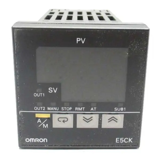
CHAPTER 1 INTRODUCTION 1.1 Names of parts JMain parts Terminals P 2-6 Output unit P 2-3 Rear case Input type jumper connector P 2-2 Front panel JFront panel No.1 display Operation indica- tors OUT1 OUT2 SUB1 MANU No.2 display Run/Reset key RUN/RST Display key Down key... -
Page 13: About The Displays
1.1 Names of parts JAbout the displays F No.1 display Displays the process value or parameter symbols. F No.2 display Displays the set point, manipulated variable or parameter settings. F Operation status • OUT1 Lights when the pulse output function assigned to control output 1" is indicators •... -
Page 14: How To Use Keys
CHAPTER 1 INTRODUCTION JHow to use keys The following describes basic key operations. To change to run operation from the reset status, press this key for one se RUN/RST cond minimum. To change to the reset status from run operation, press this key for two se conds minimum. -
Page 15: Input And Output
Error 1 Error 2 Error 2 JInput The E5CK T supports the following inputs: Temperature input, Current input, Voltage input, and Event input. F Temperature input/Voltage input/Current input • Only one of temperature input, current input and voltage input can be selected and connected to the controller. -
Page 16: Output
CHAPTER 1 INTRODUCTION JOutput The output functions of the E5CK T do not operate for five seconds after the E5CK T is turned ON. The E5CK T supports the following five outputs: Control output 1 Control output 2 Auxiliary output 1 Transfer output When using control output 1 and 2, set the output unit (sold separately). -
Page 17: Program
1.3 Program 1.3 Program JHow E5CK-T allows you to configure programs made up of a maximum of four programs patterns (pattern 0 to 3) each comprising a maximum of 16 steps. are structured The number of patterns and steps in each pattern can be specified in pa rameters. -
Page 18: Parameters And Menus
CHAPTER 1 INTRODUCTION 1.4 Parameters and Menus JParameter types E5CK T parameters are distributed between the following ten modes: Protect mode Manual mode Level 0 mode Program mode Level 1 mode Level 2 mode Setup mode Expansion mode Option mode... -
Page 19: Selecting Modes
1.4 Parameters and Menus F Expansion mode This is the mode for setting expanded functions. In this mode, you can set SP setting limitter, switching between advanced PID control or ON/OFF control, program time unit, selection of step time/rate of rise program ming, time unit of ramp rise rate, and the time for automatic return to the monitoring display. -
Page 20: Fixing Settings
CHAPTER 1 INTRODUCTION • If you select [ ], [ ], [ ] or [ ] in the menu display, the level 0, program, level 1 and level 2 modes, respectively, are selected. These modes are selected with control still continuing. •... -
Page 21: About The Communications Function
1.5 About the Communications Function 1.5 About the Communications Function The E5CK T can be provided with a communications function that allows you to check and set controller parameters from a host computer. If the communications function is required, add on the communications unit. -
Page 22: About Calibration
The E5CK T controller is calibrated before shipment from the factory. So, the user need not calibrate the E5CK T controller during regular use. However, if the E5CK T controller must be calibrated by the user, use the parameters provided for the user to calibrate temperature input, analog input (voltage, current) and transfer output. -
Page 23: Chapter 2 Preparations
PREPARATIONS This chapter describes the operations (e.g. setup, installation and wir ing) you should carry out before turning the E5CK T ON. 2.1 Setup ....... . . -
Page 24: Setup
CHAPTER 2 PREPARATIONS 2.1 Setup The following section describes how to draw out the internal mechanism from the housing and how to set the input type jumper. JDraw-out Draw out the internal mechanism from the housing. (1) Press in both of the hooks on the left and right sides of the front panel to unlock the internal mechanism from the housing. -
Page 25: Setting Up The Output Unit
2.1 Setup JSetting up the output unit F Output unit list The following table shows the output units that can be set in the E5CK controller. Specifications Model (control output 1/control output 2) E53-R4R4 Relay/Relay E53-Q4R4 Voltage (NPN)/Relay E53-Q4HR4 Voltage (PNP)/Relay... -
Page 26: Installation
CHAPTER 2 PREPARATIONS 2.2 Installation JDimensions OUT1 OUT2 MANU STOP RMT SUB1 E5CK JPanel cutout 65 min. Unit (mm) 60 min. +0.6 • Recommended panel thickness is 1 to 5 • Maintain the specified vertical and hori zontal mounting space between each con +0.6... -
Page 27: Mounting
Panel Watertight packing (1) Insert the E5CK controller into the mounting hole in the panel at the position shown in the figure above. (2) Push the adapter along the controller body from the terminals up to the panel, and fasten temporarily. -
Page 28: Wiring Terminals
11 12 24 VAC, 50/60 Hz, 6 VA 24 VDC, 3.5W 13 14 The E5CK has independent power supplies for each of the ter About the power minal blocks shown on the right. However, note that the 11 12 blocks power supplies for blocks C (exclude relay output) and D are shared for the following option unit. - Page 29 2.3 Wiring Terminals F Input • Connect the sensor input to terminal Nos. 6 to 8 as follows according to the input type. 11 12 13 14 Thermocouple Platinum resistance Voltage input Current input thermometer TC ⋅ PT • Set the input type jumper inside the controller matched to the input type.
- Page 30 CHAPTER 2 PREPARATIONS F Auxiliary output 1 • Terminal Nos.2 and 3 are for auxiliary output 1 (SUB1). • The internal equalizing circuit for auxiliary output 1 is as follows: 11 12 13 14 • Relay specifications are as follows: 1a, 250 VAC, 1 A F Option •...
-
Page 31: Chapter 3 Basic Operation
CHAPTER CHAPTER 3 BASIC OPERATION This chapter describes actual examples for understanding the basic op eration of the E5CK T. 3.1 Convention Used in this Chapter ..3.2 Setting Input Specifications ... . . -
Page 32: Convention Used In This Chapter
CHAPTER 3 BASIC OPERATION 3.1 Convention Used in this Chapter This chapter describes basic E5CK T operations such as how to set up pa rameters, start and stop operation, and adjust control operation. For more complex control examples, refer to Chapter 4 Applied Operation and Chapter 5 Parameters. - Page 33 • The following figures show terminal wiring and the program used in the setting examples. Temperature sensor K thermocouple Humidifier Control target OUT1 AC100-240V (AC/DC24V ) OUT2 11 12 Alarm 1 (deviation upper-and lower-limit) 13 14 E5CK–T Step 1 Step 2 Step 3 Pattern 0 0.20 0.40 0.20 Time: hr, min 3–3...
-
Page 34: Setting Input Specifications
CHAPTER 3 BASIC OPERATION 3.2 Setting Input Specifications Setting input specifications Setup mode Input type Temperature input? Temperature unit Scaling Decimal point Level 2 mode Temperature input shift End of setup • With temperature input, scaling and decimal point parameters need not be set as this information is determined by the input (sensor) type. - Page 35 3.2 Setting Input Specifications JTemperature input F Temperature unit • To switch the temperature unit from _C" to_F" when input is temper ature, switch the _C/_F selection" parameter (setup mode) from " to ". F Temperature • When input is temperature input, the upper and lower limit values of the sensor can be shifted linearly.
-
Page 36: Input Type
CHAPTER 3 BASIC OPERATION In this example, let's check the input type and temperature units, and shift Setting Example the lower limit by 1_C and the upper limit by 3_C. input type" = 2: K1" temperature unit" = _C" input shift upper limit"= 3.0" input shift lower limit"... -
Page 37: Setting Output Specifications
3.3 Setting Output Specifications 3.3 Setting Output Specifications JOutput assignments F Standard type • Twelve outputs are supported. These functions are assigned to control outputs 1 and 2, and auxiliary outputs 1 and 2. • Restrictions on assignment destination are placed on some of the out puts. -
Page 38: Direct/Reverse Operation
CHAPTER 3 BASIC OPERATION JControl period • The control period is set in the control period (heat)" parameter (level 1 mode). The control period (heat)" parameter is factory set to 20:20 seconds." The control period (cool)" output function is not assigned. (the control period (cool)"... -
Page 39: Setting Alarm Type
• The contact conditions for when alarm output is ON can be set to open" or closed" in the close in alarm/open in alarm" parameter. JAlarm type • The following table shows the alarm types supported by the E5CK T controller and their respective operations. Alarm Output Operation... -
Page 40: Alarm Value
CHAPTER 3 BASIC OPERATION JAlarm hysteresis • The hysteresis of alarm outputs when alarms are switched ON/OFF can be set as follows: Upper limit alarm Lower limit alarm Alarm hysteresis Alarm hysteresis Alarm value Alarm value • Alarm hysteresis is set independently for each alarm in the alarm 1 to 3 hysteresis"... - Page 41 3.4 Setting Alarm Type F Summary of The figure below visually summarizes the above descriptions of alarm op erations (when alarm type is set to lower limit alarm with standby se alarm operations quence"): Alarm type: lower limit alarm with standby sequence Alarm value Alarm hysteresis...
- Page 42 CHAPTER 3 BASIC OPERATION Alarm 2 is output when the temperature exceeds alarm value 2 pro Setting Example grammed to the SP . Parameter factory settings for alarm type 2," alarm hysteresis" and close in alarm/open in alarm" are used. In this example, the related parameters are set as follows: alarm type 2"...
-
Page 43: Setting Patterns
3.5 Setting Patterns 3.5 Setting Patterns If you want to set parameters in the program mode during controller operation, you must first stop operation. Operation may continue only in special instances, for example, to change SP during controller operation. • This section describes the procedure to follow when setting two or more patterns. - Page 44 CHAPTER 3 BASIC OPERATION JPattern No. • This parameter cannot be changed during controller operation. • Set the desired pattern No. Step SP , step time, alarms and other parame ters that follow this parameter are set for the pattern that is set in this parameter.
- Page 45 3.5 Setting Patterns JAlarm value • Alarm values can be set only for alarms that have been assigned as out put. • When a deviation alarm is assigned as output, the alarm value is set with respect to SP . The following example shows the relationship between the : : 0 to 3 SP and alarm value when the alarm type is set to upper limit."...
-
Page 46: Alarm Value
CHAPTER 3 BASIC OPERATION In this example, let's set the next program to pattern 0. Setting Example Step 1 Step 2 Step 3 1 second min. 0.20 0.40 0.20 Time: hr, min Time Alarm (hr, min.) value 2 • Pattern execution count 1" Step 0 0.00 •... - Page 47 3.5 Setting Patterns (12) As the setting in this example is to be left as it is, set the alarm value. Press the key until [ ] (alarm 2" parameter) is displayed. Default is 0". (13) Set the parameter to 10: 10 seconds" pressing the keys.
-
Page 48: Protect Mode
CHAPTER 3 BASIC OPERATION 3.6 Protect Mode JSecurity • This parameter allows you to protect until start of operation parameters that do not change during operation to prevent unwanted modification. • The set value of the security" parameter (protect mode) limits the range of protectable parameters. -
Page 49: Key Protect
3.6 Protect Mode Setting Example In this example, let's set the parameters as follows: Security" 2" (all parameters in modes other than the setup mode are protected) Key protect" 1" (Auto/manual key operation cannot be switched) (1) Press the keys simultaneously for 1 second mini RUN/RST 1 second min. -
Page 50: Starting And Stopping Operation
CHAPTER 3 BASIC OPERATION 3.7 Starting and Stopping Operation • To start program operation (that is, switch from the reset state to run RUN/RST operation), press the key for one second minimum. RUN/RST • To stop program operation (that is, switch from run operation to the re set state), press the key from two seconds minimum. -
Page 51: Adjusting Control Operation
3.8 Adjusting Control Operation 3.8 Adjusting Control Operation JChanging • Programs are changed in the program mode. Note that pattern Nos. can not be changed during program operation. So, only the pattern that is programs currently running can be changed. •... - Page 52 CHAPTER 3 BASIC OPERATION In the following example, let's change the temperature set point to 60_C" Setting Example from 50_C". (1) Press the key for one second minimum at the currently executing PV/Present SP" display. (2) The display changes to the menu display. 1 second min.
- Page 53 3.8 Adjusting Control Operation JManual operation • The manipulated variable is controlled manually. • To set manual operation and manually set the manipulated variable, press the keys simultaneously for 1 second minimum. The controller enters the manual mode. To quit the manual mode, press the keys simultaneously again for 1 second minimum.
- Page 54 CHAPTER 3 BASIC OPERATION JAuto-tuning • AT (auto tuning) cannot be executed while operation is reset or during ON/OFF control. (A.T.) • When you execute auto tuning, the optimum PID parameters are auto matically set by forcibly changing the manipulated variable to calculate the characteristics (called the limit cycle method") of the control target.
- Page 55 For details on the setting ranges of these parameters, see chapter 5 Level 1 Mode (page 5 17). The E5CK T differs from fixed value type controllers in that the SP changes auto AT Execution Tim- matically . So, the timing of AT execution is the most important factor in control.
- Page 56 CHAPTER 3 BASIC OPERATION 3–26...
-
Page 57: Chapter 4 Applied Operation
CHAPTER 4 APPLIED OPERATION This chapter describes each of the parameters required for making full use of the features of the E5CK T. Read this chapter while referring to the parameter descriptions in chap ter 5. 4.1 Selecting the Control Method . -
Page 58: Selecting The Control Method
CHAPTER 4 APPLIED OPERATION 4.1 Selecting the Control Method JHeating and Heating and cooling control is achieved when the control output (cool)" function is assigned as the output. Discriminately use standard heating cooling control control or cooling control according to the following table: Parameter Control Output 1 Control Output 2... -
Page 59: Manual Operation
4.1 Selecting the Control Method F Manipulated vari- • In heating and cooling control, the manipulated variable output that is output when controller operation is stopped is dependent on the set val able at reset ue of the MV at reset" parameter (level 2 mode) in the same way as for standard control. -
Page 60: Heating And Cooling Control
CHAPTER 4 APPLIED OPERATION JON/OFF control • Switching between advanced PID control and ON/OFF control is car ried out by the PID/ON/OFF" parameter (expansion mode). When this parameter is set to [ ], advanced PID control is selected, and when set to [ ], ON/OFF control is selected. -
Page 61: Operating Condition Restrictions
If limiter a change in the manipulated variable exceeds this parameter setting, the value calculated by the E5CK T is reached while changing the value by the per second value set in this parameter. Output (%) -
Page 62: Set Point Limiter
CHAPTER 4 APPLIED OPERATION F Limiter operation The limitters are disabled or cannot be set when any of the following conditions occurs: conditions • During ON/OFF control • During AT execution (only by MV change rate limitter) • During manual operation •... -
Page 63: Ramp Rise Rate Setup Program
Chapter 3 described programs that used the time setup method." Pro grams were executed using a combination of SPs and step time values. The E5CK T also supports the ramp rise rate setup method." By this method, programs are executed using three program elements: target SP", rate of rise"... - Page 64 CHAPTER 4 APPLIED OPERATION F Relationship with When the number of steps is set to an odd number, the final soak time can not be set. For example, if we set the number of steps" parameter to 7", the number of the soak time 3"...
- Page 65 4.3 Ramp Rise Rate Setup Program JProgram example Let's describe a typical example of a ramp rise rate setup program. In an actual program, set the parameters to match the application. Step 0 Step 1 Step 2 Step 3 Target SP 0 : 100 Target SP 1 : 10...
-
Page 66: Program Operation
CHAPTER 4 APPLIED OPERATION 4.4 Program Operation JHold/advance • Steps in currently executing programs can be forcibly stopped (Hold) and advanced (Advance). • Hold and Advance operation is according to the following procedure: Run in level 0 mode Check step No. Hold? Hold = ON Continue... - Page 67 4.4 Program Operation JPattern operation F Repeating execu- • To repeatedly execute the same pattern, set the number of times that the pattern is to be executed in the pattern execution count" parameter tion of the same (program mode). pattern •...
- Page 68 CHAPTER 4 APPLIED OPERATION Parameters Symbol Parameter Name: Mode Description Hold : Level 0 Pauses program execution. Advance : Level 0 Advances the program one step. Repeatedly executes current Pattern execution count : Program pattern. Run all :Expansion Executes all patterns. •...
-
Page 69: Program Output
4.5 Program output 4.5 Program output • The E5CK T outputs the following signals according to how far the pro gram has elapsed: Time signal 1/2 Program end Stage output • These functions can be used only when they have been assigned as outputs. - Page 70 CHAPTER 4 APPLIED OPERATION JProgram status F Program end • One second pulse signal is output after the final step is completed. Time Final step Program end output F Stage output • One second pulse signal is output at the beginning of each step. Time Stage output Parameters...
-
Page 71: Setting Running Conditions
4.6 Setting Running Conditions 4.6 Setting Running Conditions JOperation at • You can select from one of the following operations at power ON: Continue, Reset, Run, Manual power ON • If you select Continue," operation is started from the state that was ac tive when power was interrupted. -
Page 72: Operation At Power
CHAPTER 4 APPLIED OPERATION JStarting the program run F PV start • When the program is configured by the time setup method, a ramp priority PV start" can be selected as one of the run start conditions. If you select PV start" in the PV start" parameter (expansion mode), program operation is started from the position of the SP that first matches the PV when program run is started. -
Page 73: How To Use Event Input
4.7 How to Use Event Input 4.7 How to Use Event Input • When using event input, add on the input unit (E53-CKB) • Switching by event input is not possible on the menu display. • Switch event inputs ON and OFF while controller power is ON. JInput •... - Page 74 CHAPTER 4 APPLIED OPERATION JDetailed • There is no order of priority in event input, key operations and commu nications command setup. However, remote/local, auto/manual, hold/ description of hold cancel or pattern selection be set to either of ON or OFF . So, param input functions eters will always follow event input even if you try to switch settings by key operation and communications commands.
-
Page 75: Lba
4.8 LBA 4.8 LBA • The LBA function can be used only when it is assigned as an output. Also, the LBA function does not work when a memory error or A/D con verter error results. • LBA (Loop Break Alarm) is a function for judging that an error has oc curred somewhere on the control loop and for outputting an alarm when the process value does not change with the manipulated variable at a maximum or minimum state. - Page 76 CHAPTER 4 APPLIED OPERATION F Setting the LBA • The LBA detection time is automatically set by auto tuning (except in heating and cooling control). detection time • If the optimum LBA detection time cannot be obtained by auto tuning, set the time in the LBA detection time"...
-
Page 77: How To Use Transfer Output
4.9 How to Use Transfer Output 4.9 How to Use Transfer Output • When using transfer output, add on the communications unit (E53 CKF). F Transfer output • You can select the following four data items in the transfer output type" parameter (option mode) as the transfer outputs: type Present SP (default), Process value, Manipulated variable (heat),... - Page 78 CHAPTER 4 APPLIED OPERATION 4–22...
-
Page 79: Chapter 5 Parameters
CHAPTER 5 PARAMETERS CHAPTER CHAPTER 5 PARAMETERS This chapter describes the parameters of the E5CK T. Use this chapter as a reference guide. Conventions Used in this Chapter ... . -
Page 80: Conventions Used In This Chapter
Model JAbout parameter display On the E5CK T controller, only parameters that can be used are displayed. These parameters are displayed only when the Conditions of Use" on the right of the parameter heading are satisfied. However, note that the settings of protected parameters are still valid, and are not displayed regardless of the conditions of use. -
Page 81: Protect Mode
Protect Mode • The protect function restricts key use to prevent unwanted key operation. Before changing parameters in this mode, first make sure that protecting the keys will not cause any problems in operation. • To select this mode, press the keys simultaneously for 1 second RUN/RST minimum. - Page 82 CHAPTER 5 PARAMETERS Protect Mode Key protect • Disables key operation of the RUN/RESET or AUTO/MANUAL. For example, if AUTO/MANUAL key operation is disabled (by simultaneously pressing the keys) in the key protect" parameter (protect mode) during automatic operation, Function manual operation is no longer possible.
-
Page 83: Manual Mode
Manual Mode • In this mode, manual operation is possible, and the MANU" LED lights. • When this mode is selected, the manipulated variable that was active immediately before the mode was switched to is output. To change the manipulated variable, use keys. -
Page 84: Level 0 Mode
CHAPTER 5 PARAMETERS Level 0 Mode • The parameters in this mode can be used only when the security" parameter (pro tect mode) is set to 0" to 5". Only the PV/Present SP" parameter can be used when the security" parameter is set to 6". •... - Page 85 Level 0 Mode Pattern No. Conditions of Use The “number of patterns” parameter must be set to a value greater than “2”. • This parameter can be set only when the controller is reset. • Displays the execution pattern during program operation, and the set pattern after the controller is reset.
- Page 86 CHAPTER 5 PARAMETERS Level 0 Mode Hold • This parameter can only be used for monitoring when the controller is reset. • Pauses (holds) or cancels program operation. • When the event input to which hold/hold cancel" is assigned is ON, [ ] (hold) is Function displayed, and when OFF [...
- Page 87 Level 0 Mode Standby time monitor Conditions of Use The controller must be in a standby state. • Displays the remaining standby time. (This time is not displayed when the controller is reset.) Function Unit Monitor Range 0.00 to 99.59 Hour, minute Monitor F Related description...
- Page 88 CHAPTER 5 PARAMETERS Level 0 Mode MV monitor (heat) Conditions of Use The control must be standard control or heating and cooling control. MV monitor (cool) • This parameter cannot be set. • Monitors the manipulated variable on the heating or cooling side. •...
-
Page 89: Program Mode
Program Mode • The parameters in this mode can be used only when the security" parameter (pro tect mode) is set to 0" to 4". • This mode contains the parameters that you use for programming. • To select this mode, press the key for 1 second minimum. - Page 90 CHAPTER 5 PARAMETERS Program Mode Number of steps • Specifies the number of steps in the current pattern. Function Setting Range Unit Default 1 to 16 None Setting F Related description 3.5 Setting Patterns (page 3 14) F Related parameter All parameters in the program mode Step 0 time (Step time) Conditions of Use...
- Page 91 Program Mode Ramp rate 0 Conditions of Use Within the number of steps only in the rate of rise programing. Ramp rate 7 • Sets the degree of change per time unit of ramp rate in the step time ramp step. Function Setting Range Unit...
- Page 92 CHAPTER 5 PARAMETERS Program Mode Pattern execution count • Executes the current pattern for the preset number of times. • The count during pattern execution can be monitored in the pattern execution count monitor" (level 0 mode). Function Setting Range Unit Default 0 to 9999...
- Page 93 Program Mode Time signal 1 enabled Conditions of Use Each of the time signals must be assigned step as outputs. Time signal 2 enabled step • Sets the step in which the time signal is used. Function Setting Range Unit Default 0 to 15 None...
- Page 94 CHAPTER 5 PARAMETERS Program Mode Time signal 1 OFF time Conditions of Use Each of the time signals must be assigned as outputs. Time signal 2 OFF time • Sets the OFF time of the time signal. Function Setting Range Unit Default 0.00 to 99.59...
-
Page 95: Level 1 Mode
Level 1 Mode • The parameters in this mode can be used only when the security" parameter (pro tect mode) is set to 0" to 3". • This mode contains the main parameters for adjusting control, such as executing AT (auto tuning), setting the control period, setting PID parameters. - Page 96 CHAPTER 5 PARAMETERS Level 1 Mode AT Execute/Cancel Conditions of Use The controller must be in operation, and control must be advanced PID control. • Selects the limit cycle of MV change width (40% or 100%) for execution. After AT execution, the PID"...
- Page 97 Level 1 Mode Cooling coefficient Conditions of Use The control must be either heating and cooling control, or advanced PID control. • In heating and cooling control, P at the cooling side is calculated by the following for mula: Cooling side P = Cooling coefficient x P Function Setting Range Unit...
- Page 98 CHAPTER 5 PARAMETERS Level 1 Mode Manual reset value Conditions of Use The control must be either standard con- trol or advanced PID control, and the “inte- gral time” parameter must be set to “0”. • Sets the required manipulated variable to remove offset during stabilization of P or PD control.
- Page 99 Level 1 Mode Control period (heat) Conditions of Use Relay, SSR or voltage output must set as the outputs, and the control must be set to Control period (cool) advanced PID control, standard control or heating and cooling control. • Sets the pulse output period. Set the control period taking the control characteristics and life expectancy of the controller into consideration.
-
Page 100: Level 2 Mode
CHAPTER 5 PARAMETERS Level 2 Mode • The parameters in this mode can be used only when the security" parameter (pro tect mode) is set to 0" to 2". • This mode contains the auxiliary parameters for adjusting control. These parame ters include parameters for limiting the manipulated variable, parameters for switching between remote and local operation, and parameters for setting the LBA (Loop Break Alarm), alarm hysteresis, and input digital filter values. - Page 101 To change the parameter setting during local operation, change the setting Function on the E5CK T controller. You can check the parameter setting by both communica tions and on the E5CK T controller regardless of whether the controller is switched to remote or local operation.
- Page 102 CHAPTER 5 PARAMETERS Level 2 Mode LBA detection time Conditions of Use The LBA (Loop Break Alarm) function must be assigned as an output. • This parameter is automatically set by AT execution. • The LBA is output if the change width of the process value falls below 0.2 %full scale of the time preset to this parameter when the manipulated variable is set in the MV Function upper limit"...
- Page 103 • The MV upper limit" and MV lower limit" parameters set the upper and lower lim its of the manipulated variable. When the manipulated variable calculated by the E5CK T controller strays from the upper and lower limit range, the upper limit or Function lower limit set to these parameters is output, respectively.
- Page 104 CHAPTER 5 PARAMETERS Level 2 Mode Input digital filter • Sets the time constant of the input digital filter. The following figures shows the effect on data after passing through the digital filter. Function PV before passing through filter PV after passing through filter 0.63A Time Time...
- Page 105 Level 2 Mode Input shift upper limit Conditions of Use The input type must be set to temperature input (thermocouple or platinum resis- Input shift lower limit tance thermometer). • Sets each of the shift amounts for the input shift upper and lower limit values. Function Unit Default...
-
Page 106: Setup Mode
0" and 1". • This mode contains the parameters for checking or setting the basic specifications of the E5CK T controller. These parameters include parameters for specifying the input type, scaling, output assignments, and direct/reverse operation. - Page 107 Setup Mode Input type • Sets the sensor type by the code. Function • Set the code according to the following table. Default is 2 : K1 thermocouple". Set value Input Type JPt100-199.9 to 650.0 (_C) /-199.9 to 999.9 (_F) Setting Platinum resistance thermometer Platinum resistance thermometer...
- Page 108 CHAPTER 5 PARAMETERS Setup Mode Scaling upper limit Conditions of Use The input type must be set to analog input (voltage or current input). Scaling lower limit Decimal point • This parameter can be used when voltage input or current input is selected as the input type.
- Page 109 Setup Mode _C/_F selection Conditions of Use The input type must be set to temperature input (thermocouple or platinum resis- tance thermometer). • This parameter can be used when thermocouple or platinum resistance thermometer is selected as the input type. •...
- Page 110 CHAPTER 5 PARAMETERS Setup Mode Control output 1 assignment Control output 2 assignment • Assigns the output functions to either of control output 1 or 2. • The following 10 output functions can be assigned as outputs: Control output (heat), Control output (cool), Alarms 1 to 3, LBA, Time signals 1 and Function 2, Program end and Stage output •...
- Page 111 Setup Mode Auxiliary output 1 assignment • Assigns output functions to auxiliary output 1. The following 10 output functions can be assigned as outputs: Alarms 1 to 3, LBA, Time signals 1 to 2, Program end, Stage output, Error 1 (input Function error), Error 2 (A/D converter error) •...
- Page 112 CHAPTER 5 PARAMETERS Setup Mode Alarm 1 type Conditions of Use Alarms must be assigned as outputs. For example, if alarm output 1 and 2 only are Alarm 2 type assigned as outputs, the “alarm 3 type” parameter cannot be used. Alarm 3 type •...
- Page 113 Setup Mode Alarm 1 open in alarm Conditions of Use Alarms must be assigned as outputs. For example, if alarm outputs 1 and 2 only are Alarm 2 open in alarm assigned as outputs, the “alarm 3 open in alarm” parameter cannot be used. Alarm 3 open in alarm •...
-
Page 114: Expansion Mode
CHAPTER 5 PARAMETERS Expansion Mode • The parameters in this mode can be used only when the security" parameter (pro tect mode) is set to 0" and 1". • This mode contains the parameters for setting expanded functions. These parame ters include parameters for setting the SP setting limitter, selecting advanced PID and ON/OFF control, and setting the program time unit, step time/rate of rise pro gramming, time unit of ramp rate and the automatic return of display mode. - Page 115 Expansion Mode Set point upper limit Set point lower limit • Limits the upper and lower limits when the SP is set. The SP can be set within the range defined by the upper and lower limit set values of the set point upper limit" and set point lower limit "...
- Page 116 CHAPTER 5 PARAMETERS Expansion Mode Operation at power ON Selects one of the following operations when the power is turned ON: • Continue" : Starts operations from the state that was active when the power was interrupted. Function • Reset" Resets the controller.
- Page 117 Expansion Mode Number of patterns • Sets the number of patterns that can be used in a program. Function Default Setting Range 1 to 4 Setting F Related parameters Run all enable" (expansion mode) Event input assignment 1" (option mode) Program time unit •...
- Page 118 CHAPTER 5 PARAMETERS Expansion Mode Step time/Rate of rise programming • Specifies the program method. Function Default Setting Range “ ” :Set time/ “ ” :Rate of rise programming Setting F Related description 3.5 Setting Patterns (page 3 14) 4.3 Ramp Rise Rate Setup Program (page 4 9) F Related parameter Step 0 to 15 SP/Target SP 0 to 7"...
- Page 119 Expansion Mode PV start Conditions of Use The set time must be set. Specifies either of the following current SP at the start of program operation: • PV : Process value at start of program operation (PV start) • SP : SP of step 0 (normal program operation) Function When PV"...
- Page 120 CHAPTER 5 PARAMETERS Expansion Mode α Conditions of Use The control must be advanced PID con- trol. • Normally, use the default value. • Sets advanced PID control parameter α. Function Unit Default Setting Range 0.00 to 1.00 None 0.65 Setting AT calculated gain Conditions of Use...
- Page 121 Expansion Mode Automatic return of display mode • If you do not operate any of the controller keys for the time set in this parameter when in levels 0 to 2 and program modes, the display automatically returns to the PV/Pres ent SP display.
-
Page 122: Option Mode
CHAPTER 5 PARAMETERS Option Mode • The parameters in this mode can be used only when the security" parameter (pro tect mode) is set to 0" and 1". • You can select this mode only on controllers that support optional functions. In this mode, you can set the communications conditions, transfer output and event input parameters to match the type of optional function supported on the controller. - Page 123 Option Mode Event input assignment 1 Conditions of Use The event input function must be in use. • The following functions are assigned as event inputs: Run/reset," Auto/manual," Hold/hold cancel," Advance," Pattern select 0 to 1" • Weighting of the remote/local function is as follows: Function Pattern select 0 = 2 , Pattern select 1 = 2...
- Page 124 • These parameters are enabled when the power is turned ON again. • These parameters set the communications conditions. Make sure that the stop bit, data length, parity and baud rate of the host computer and the E5CK T controller are Function matching.
- Page 125 Option Mode Conditions of Use Transfer output type The transfer output function must be in use. Transfer output upper limit Transfer output lower limit • These parameters set the transfer output conditions. • The transfer output type" parameter selects one of the following data items as the transfer output type, and assigns this to transfer output: Function Present SP , Process value, Manipulated variable (heat), Manipulated variable (cool)
-
Page 126: Calibration Mode
CHAPTER 5 PARAMETERS Calibration Mode • The parameters in this mode can be used only when the security" parameter (pro tect mode) is set to 0". When selecting this mode for the first time after the E5AK T has left the factory, return the security" parameter to 0". •... -
Page 127: Chapter 6 Using The Communications Function
CHAPTER 6 USING THE COMMUNICATIONS FUNCTION CHAPTER CHAPTER 6 USING THE COMMUNICATIONS FUNCTION This chapter mainly describes communications with a host computer and communications commands. 6.1 Outline of the Communications Function Outline ....... Transfer procedure . -
Page 128: Outline Of The Communications Function
6.1 Outline of the Communications Function JOutline The communications function allows you to monitor and set E5CK T pa rameters by a program prepared and running on a host computer con nected to the E5CK T controller. This chapter describes operations as viewed from the host computer. -
Page 129: Preparing For Communications
• Use terminators having a resistance of 120 Ω (1/2 W). The total resis tance of both ends should be at least 54 Ω. Host computer RS-485 A < B : “1” Mark Shielded cable A > B : “0” Space Terminator (120Ω 1/2W) E5CK-T (No.0) E5CK-T (No.30) RS-485 RS-485 6–3... - Page 130 This section describes how to set the communications specifications for the E5CK T controller. For details on the host computer, see the relevant manual supplied with the host computer. F Communications Set the communications specifications of the E5CK T in the controller's communications parameters.
-
Page 131: Command Structure
The start character. This character must be inserted before the leading byte. • Unit No. Specifies the unit No." of the E5CK T. If there are two or more trans mission destinations, specify the desired destination using unit No." • Command type... - Page 132 CHAPTER 6 USING THE COMMUNICATIONS FUNCTION • End code Sets the communication results. For details on the types and meanings of end codes, see 6.5 How to Read Communications Error Information (page 6 12). • FCS (Frame Check Sequence) Set the frame check results from the start character to the data area. For details on the frame check, see 6.6 Program Example (page 6 18).
-
Page 133: Commands And Responses
6.4 Commands and Responses 6.4 Commands and Responses This section describes commands and response in detail. The conventions used in this section and data restrictions are as follows: • Data is expressed in 1 byte units and in ASCII code. •... - Page 134 CHAPTER 6 USING THE COMMUNICATIONS FUNCTION Parameter No. Parameter Data Setting and Monitor Range Mode PV monitor *1 *2 Scaling lower limit -10% to scaling upper limit +10% Set point Set point lower limit to set point upper limit Level 0 Level 0 MV monitor (heat) -5.0 to 105.0...
- Page 135 6.4 Commands and Responses Parameter No. Parameter Data Setting Range Mode Input type 0 to 21 Scaling upper limit Scaling lower limit +1 to 9999 Scaling lower limit -1999 to scaling upper limit -1 Decimal point 0 to 3 _C/_F selection 0: _C, 1: _F Control output 1 assignment 0 to 4, 6, 10 to 13...
-
Page 136: Issuing Special Commands
• Move to setting level 1 Issue this command when writing parameters in the setup, expansion and option modes. On the E5CK T, the parameter switches to the top pa rameter : input type" of the setup mode, and control is stopped. - Page 137 6.4 Commands and Responses F A group Description Heating side output Cooling side output Alarm output 1 Alarm output 2 Alarm output 3 LBA output Run/Reset Reset Auto/Manual Manual Auto Remote/Local Remote Local AT execution Hold During hold F B group Description Setting level Control output 1 type...
-
Page 138: Reading/Writing Program Parameters
CHAPTER 6 USING THE COMMUNICATIONS FUNCTION JReading/writing program parameters Reading parameters Unit Parameter Command Unit Parameter Read data Response code Writing parameters Unit Parameter Write data Command Unit Parameter Write data Response code Parameters relating to the program of the specified unit are read or writ ten. - Page 139 6.4 Commands and Responses Parameter No. Parameter Data Setting and Monitor Range Mode Pattern No. 0 to number of patterns -1 Step No. monitor 0 to number of steps -1 Standby time monitor 0.00 to 99.59 Level 0 Level 0 Pattern elapsing time monitor 0.00 to 99.59 Pattern execution count monitor *1...
- Page 140 CHAPTER 6 USING THE COMMUNICATIONS FUNCTION Parameter No. Parameter Data Setting and Monitor Range Mode Step 14 SP SP lower limit to SP upper limit Step 14 time 0.00 to 99.59 Step 15 SP SP lower limit to SP upper limit Step 15 time 0.00 to 99.59 Pattern execution count...
-
Page 141: How To Read Communications Error Information
6.5 How to Read Communications Error Information The result of communications on the E5CK T can be checked by the end code or undefined error response in the response frame. Use this end code or undefined error response to remedy errors that may occur. -
Page 142: Undefined Error
F Action Check the communications conditions. If the communications conditions of the host computer and E5CK T controller match, then a probable cause is a problem in the communications circuit of one or both of the host com puter and E5CK T controller. -
Page 143: Program Example
6.6 Program Example 6.6 Program Example JHow to use programs The program described below obtains corresponding response frame data when some of the command frame data is input. The input format is as follows. The FCS and terminator are automatically generated, and need not be input. - Page 144 CHAPTER 6 USING THE COMMUNICATIONS FUNCTION JProgram list (language: IBM PC Compatible Machine) 1000 ’ 1010 ’ PROGRAM : E5CK-T COMMUNICATION PROGRAM 1020 ’ FOR IBM PC COMPATBLE MACHINE 1050 ’ 1060 ’ Default RS-232C SPEED: 9600BPS, PARITY: EVEN, DATA: 7, STOP: 2 1070 OPEN “COM: E73”...
-
Page 145: Examples Of Use
6.6 Program Example JExamples of use • Set the unit No. to 00". • In the following examples, data is shown in individual blocks to make the examples easier to understand. However, when actually creating programs, do not leave spaces between frame items. - Page 146 CHAPTER 6 USING THE COMMUNICATIONS FUNCTION 6–20...
-
Page 147: Chapter 7 Calibration
CHAPTER 7 CALIBRATION CHAPTER CHAPTER 7 CALIBRATION This chapter describes procedures for each calibration operation. Read this chapter only when the controller must be calibrated. 7.1 Parameter Structure ....7.2 Calibrating Thermocouples . -
Page 148: Parameter Structure
• However, note that [ ] may not be displayed on the menu display when, for example, the user is calibrating the E5CK T controller for the first time. If this happens, [ ] is displayed by changing the security"... - Page 149 F Calibration store • Once the E5CK T controller has been calibrated by the user, [ ] is displayed preceded by the ." mark when the calibration mode is next se mark lected.
-
Page 150: Calibrating Thermocouples
(K1, J1, L1, E, N, W, PLII) and thermocouple 2 group (K2, K2, L2, R, S, B, T, U). • When calibrating, do not cover the bottom of the controller. Also, do not touch the input terminals (Nos.6 and 7) or compensating conductor on the E5CK T controller. F Preparations AC100-240V (AC/DC24V... - Page 151 7.2 Calibrating Thermocouples F Calibration: This example describes how to calibrate a thermocouple when the transfer output function is supported. If the transfer output function is not sup thermocouple 1 ported, skips steps (7) to (10). (1) When [ ] is displayed, the 30 minute timer is displayed on the No.2 display and counts down.
- Page 152 CHAPTER 7 CALIBRATION F Calibration: ther- This example describes how to calibrate a thermocouple when the transfer output function is supported. If the transfer output function is not sup mocouple 2 ported, skips steps (7) to (10). (1) When [ ] is displayed, the 30 minute timer is displayed on the No.2 display and counts down.
-
Page 153: Calibrating Platinum Resistance Thermometers
7.3 Calibrating Platinum Resistance Thermometers 7.3 Calibrating Platinum Resistance Thermometers F Preparation AC100-240V (AC/DC24V SOURCE 6-dial • Use leads of the same thickness when connecting to the platinum resis tance thermometer. • In the above figure, 6 dial refers to a precision resistance box, and DMM stands for a digital multimeter. - Page 154 CHAPTER 7 CALIBRATION From previous page (5) Press the key to display [ ] (10Ω calibration display). Set the 6 dial to 10Ω. When the value on the No.2 display has stabilized (changes of several digits max.), press the key to temporarily store the calibration data.
-
Page 155: Calibrating Current Input
7.4 Calibrating Current Input 7.4 Calibrating Current Input F Preparation AC100-240V (AC/DC24V SOURCE F Calibration • In the above figure, STV refers to a standard DC current/voltage source, and DMM refers to a precision digital multimeter. However, note that the DMM is required only when the transfer output function is sup ported. -
Page 156: Calibrating Voltage Input
CHAPTER 7 CALIBRATION 7.5 Calibrating Voltage Input F Preparation AC100-240V (AC/DC24V SOURCE • In the above figure, STV refers to a standard DC current/voltage source, and DMM refers to a precision digital multimeter. However, note that the DMM is required only when the transfer output function is sup ported. - Page 157 7.5 Calibrating Voltage Input From previous page (8) Press the key until the display changes to the data store display. Press the key. The No.2 display changes to [ ], and two se conds later the calibration data is stored to internal memory. If you press the [ ] key when the No.2 display reads [ ], the calibra...
- Page 158 • After calibrating input, be sure to check indication accuracy to make sure that the E5CK T controller has been correctly calibrated. • Operate the E5CK T controller in the PV/SP monitor (level 0 mode) mode. • Check the indication accuracy at the upper and lower limits and mid point.
- Page 159 7.6 Checking Indication Accuracy F Current input or • Preparation The following figure shows the required device connection. Voltage input AC100-240V (AC/DC24V SOURCE • Operation Set the STV to the current value equivalent to the check value or set the STV to the voltage value equivalent to the check value.
- Page 160 CHAPTER 7 CALIBRATION 7–14...
- Page 161 This chapter describes how to find out and remedy the cause if the E5CK T does not function properly. Remedy E5CK T trouble in the order of the descriptions in this chapter 8.1 Initial Checks ......
- Page 162 E5AK T controller are matching, and are within the permissible ranges. If there appears to be nothing wrong after checking the E5CK T controller, and the same phenomenon continues, check the controller in more detail, for example, on the error display.
- Page 163 First, turn the power OFF then back ON again. If the display remains the same, the E5CK T controller must be repaired. If the display is restored to normal, then a probable cause can be external noise affecting the control system.
- Page 164 ON. F Meaning Calibration data is in error. F Action E5CK T must be repaired. F Operation at Both control output functions and alarm output functions operate. How ever, note that readout accuracy is not assured.
- Page 165 8.3 How to Use the Error Output 8.3 How to Use the Error Output The E5CK T controller allows you to assign error output to terminals as outputs. For details on output assignments, see 3.3 Setting Output Specifications (page 3 7).
- Page 166 CHAPTER 8 TROUBLESHOOTING 8.4 Checking Operation Restrictions With the E5CK T controller, auto tuning or self tuning sometimes do not operate depending on how functions are combined. The table below sum marizes the main operating restrictions. If the E5CK T controller is not operating properly, first check whether op erating conditions violate the restrictions in this table.
- Page 167 APPENDIX APPENDIX SPECIFICATIONS ......CONTROL BLOCK DIAGRAM ....SETTING LIST .
- Page 168 The Netherlands Tel: (31)2356-81-300/Fax: (31)2356-81-388 OMRON ELECTRONICS LLC 1 East Commerce Drive, Schaumburg, IL 60173 U.S.A. Tel: (1)847-843-7900/Fax: (1)847-843-8568 OMRON ASIA PACIFIC PTE. LTD. 83 Clemenceau Avenue, #11-01, UE Square, 239920 Singapore Tel: (65)6835-3011/Fax: (65)6835-2711 OMRON (CHINA) CO., LTD. Room 2211, Bank of China Tower,...
-
Page 169: Specifications
APPENDIX SPECIFICATIONS JRatings Supply voltage 100 to 240V AC, 50/60 Hz 24 VAC/DC, 50/60 Hz Operating Voltage 85% to 110% of rated supply voltage Range Power Consumption 15VA 6 VA, 3.5 W *1, *2 Thermocouple: K, J, T, E, L, U, N, R, S, B, W, PLII *1, *2 Platinum resistance thermometer: JPt100, Pt100 Sensor Input Voltage input: 4 to 20 mA, 0 to 20 mA (input impedance 150Ω) - Page 170 SPECIFICATIONS JCharacteristics Thermometer: (±0.3% of indication value or ±1°C, whichever greater) ±1 digit max. (*1) Indication Accuracy Platinum resistance thermometer: (±0.2% of indication value or ± 0.8°C whichever greater) ±1 digit max. Analog input: ±0.2%FS±1 digit max. Platinum resistance thermometer: Temperature variation influ- (±1% of PV or ±...
- Page 171 APPENDIX JSensor Input Setting Ranges and Indication Ranges Input Setting Range Indication Range JPt100 -199.9 to 650.0 (C°) / -199.9 to 999.9 (F°) -199.9 to 735.0 (C°) / -199.9 to 999.9 (F°) Pt100 -199.9 to 650.0 (C°) / -199.9 to 999.9 (F°) -199.9 to 735.0 (C°) / -199.9 to 999.9 (F°) -200 to 1300 (C°) / -300 to 2300 (F°) -350 to 1450 (C°) / -560 to 2560 (F°) -0.0 to 500.0 (C°) / -0.0 to 900.0 (F°)
-
Page 172: Control Block Diagram
CONTROL BLOCK DIAGRAM CONTROL BLOCK DIAGRAM Temperature Analog input input Digital filter Digital filter Input shift Scaling limitter Input type Program Process/function Control method Control Control mode Control mode Data ON/OFF ON/OFF control PID control PID control control 3-position control Heating Cooling side... -
Page 173: Setting List
APPENDIX SETTING LIST Mode Parameter Name Setting Range Unit Default Remarks Setting Security 0 to 6 None Protect Protect Key protect 0/1/2/3 None Manual Manual MV -5.0 to 105.0 Pattern No. 0 to number of patterns -1 None At program opera- Hold OFF/ON None... - Page 174 SETTING LIST Mode Parameter Name Setting Range Unit Default Remarks Setting Remote/Local RMT/LCL None Hour, Standby time 0.00 to 99.59 0.00 Min. LBA detection time 0 to 9999 MV at reset -5.0 to 105.0 MV at PV error -5.0 to 105.0 MV upper limit MV lower limit +0.1 to 105.0 105.0...
- Page 175 APPENDIX Mode Parameter Name Setting Range Unit Default Remarks Setting Set point upper limit 1300 Set point lower limit +1 to scaling upper limit Set point lower limit -200 Scaling lower limit to Set point upper limit -1 PID / ON/OFF PID / ON/OFF None Operation at power ON...
- Page 176 SETTING LIST A–9...
-
Page 177: Model List
Terminal cover E53-COV07 Terminal cover for E5CK-T The output unit is required for E5CK-TAA1 (including -500). For details on the output unit, see page 2-3. When adding on the option unit, also see the option unit list on page 2-3. A–10... -
Page 178: Parameter Operations List
PARAMETER OPERATIONS LIST PARAMETER OPERATIONS LIST • Switching to modes other than the manual or protect mode is carried out by mode selection in the menu display. • The figure below shows all parameters in the order that they are displayed. Some parameters are not displayed depending on the protect mode setting and conditions of use. - Page 179 APPENDIX Setup Level 2 Expansion Remote/Local Input type Set point upper limit Standby time Scaling upper limit Set point lower limit LBA detection time Scaling lower limit PID / ON/OFF MV at reset Decimal point Operation at power ON °C/°F selection MV at PV error End condition MV upper limit...
-
Page 180: Ascii Code List
ASCII CODE LIST ASCII CODE LIST Upper 4 bits 0000 0001 0010 0011 0100 0101 0110 0111 0000 0001 0010 ” 0011 0100 0101 0110 & 0111 ’ 1000 1001 1010 1011 1100 < ¥ 1101 1110 > 1111 Lower 4 bits A–13... - Page 181 INDEX Auto/Manual ..... . . 4-18 Symbols Auxiliary output 1 ....°C/°F selection .
- Page 182 INDEX Control period (heat) ....5-21 Input ....... Convention Used in this Chapter .
- Page 183 INDEX Number of patterns ....5-39 Program structure ....Proportional band .
- Page 184 INDEX Stage output ......4-14 Thermocouple ..... . 7-12 Standard type .
- Page 185 Revision History A manual revision code appears as a suffix to the catalog number on the front cover of the manual. Cat. No. H090 E1 01B Revision code The following table outlines the changes made to the manual during each revision. Page numbers refer to previous version.
- Page 186 The Netherlands Tel: (31)2356-81-300/Fax: (31)2356-81-388 OMRON ELECTRONICS LLC 1 East Commerce Drive, Schaumburg, IL 60173 U.S.A. Tel: (1)847-843-7900/Fax: (1)847-843-8568 OMRON ASIA PACIFIC PTE. LTD. 83 Clemenceau Avenue, #11-01, UE Square, 239920 Singapore Tel: (65)6835-3011/Fax: (65)6835-2711 OMRON (CHINA) CO., LTD. Room 2211, Bank of China Tower,...
Need help?
Do you have a question about the e5ck and is the answer not in the manual?
Questions and answers