Table of Contents
Advertisement
Quick Links
Advertisement
Chapters
Table of Contents

Related Manuals for Omron E5CK


Summary of Contents for Omron E5CK
- Page 1 Cat. No. H078-E1-03D E5CK Digital Controller USER´S MANUAL...
-
Page 2: About This Manual
(2) No patent liability is assumed with respect to the use of the information contained herein. (3) Moreover, because OMRON is constantly striving to improve its high-quality products, the information in this manual is subject to change without notice. Every precaution has been taken in the preparation of this manual. -
Page 3: Conventions Used In This Manual
J OMRON Product References All OMRON products are capitalized in this manual. The word “Unit” is also capitalized when it refers to an OMRON product, regardless of whether or not it appears in the proper name of the product. The abbreviation “Ch,” which appears in some displays and on some OMRON products, often means “word”... -
Page 4: Chapter 1 Introduction 1
Chapter 4 Applied Operation These chapters describe the Chapter 5 Parameters important functions of the E5CK and how to use the parameters for making full use of the E5CK. Communications with a Chapter 6 Using the Commu- This chapter mainly describes nications Function... -
Page 5: Pay Attention To The Following When Installing This Controller
Pay Attention to the Following when Installing this Controller F If you remove the controller from its case, never touch nor apply shock to the electronic parts inside. F Do not cover the top and bottom of the controller. (Ensure sufficient space around the controller to allow heat to escape.) F Use a voltage (AC100-240V or AC/DC24V at 50 to 60 Hz). -
Page 6: Table Of Contents
..... 4--1 This chapter describes each of the parameters required for making full use of the features of the E5CK. Read this chapter while referring to the parameter descrip- tions in chapter 5. 4.1 Selecting the Control Method . - Page 7 ..... . 7--1 This chapter describes how to find out and remedy the cause if the E5CK does not function properly.
-
Page 8: Input And Output 1
CHAPTER 1 INTRODUCTION CHAPTER CHAPTER 1 INTRODUCTION This chapter introduces the E5CK. First-time users should read this chapter without fail. For details on how to use the controller and parameter settings, see Chapters 2 onwards. 1.1 Names of parts ...... -
Page 9: Chapter 1 Introduction
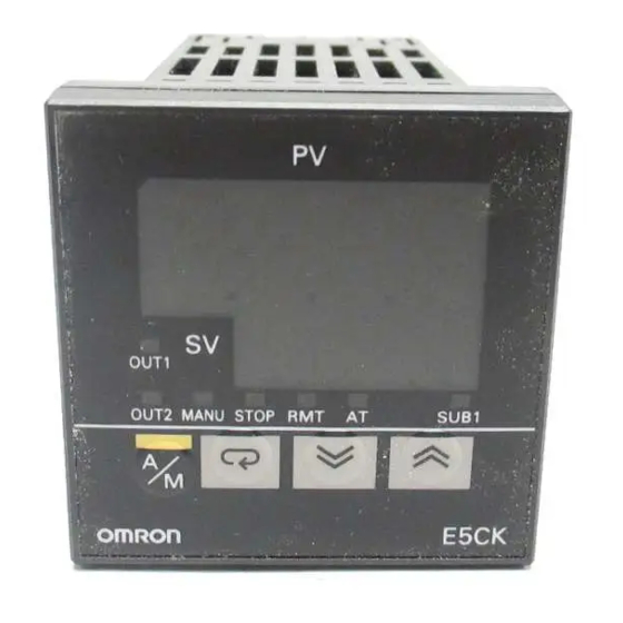
P 2-2 Option unit P 2-3 Front panel J Front panel Operation indica- No.1 display tors OUT1 OUT2 SUB1 MANU No.2 display STOP OUT1 OUT2 MANU STOP RMT SUB1 A/M key E5CK Display key Down key Up key 1--2... -
Page 10: About The Displays
1.1 Names of parts J About the displays F No.1 display Displays the process value or parameter symbols. F No.2 display Displays the set point, manipulated variable or parameter settings. F Operation indica- • OUT1 : Lits when the pulsed output function assigned to “control tors output 1”... -
Page 11: Input And Output
Error 1 Error 2 J Input The E5CK supports four inputs. F Temperature input/Voltage input/Current input • Only one of temperature input, voltage input and current input can be selected and connected to the controller. The above figure shows temper- ature input connected to the controller. - Page 12 Eight output units are available to suit the output circuit configuration. When using transfer output, add on the communication unit (E53---CKF). Note: The output functions of the E5CK do not operate for five seconds af- ter the E5CK is turned ON.
-
Page 13: Parameters And Menus
CHAPTER 1 INTRODUCTION 1.3 Parameters and Menus J Parameter types E5CK parameters are distributed between the following nine modes. Protect mode Manual mode Level 0 mode Level 1 mode Level 2 mode Setup mode Expansion mode Option mode Calibration mode... -
Page 14: Output
1.3 Parameters and Menus F Option mode This is the mode for setting option functions. You can select this mode only when the option unit is set in the controller. In this mode, you can set the communications conditions, transfer output and event input parameters to match the type of option unit set in the controller. -
Page 15: Selecting Parameters
CHAPTER 1 INTRODUCTION F Setup mode • If you select [ ] or [ ] in the menu display, the F Expansion mode setup, expansion, option and calibration modes, respectively, are F Option mode selected. F Calibration mode • When these modes are selected, the control is reset. So, control outputs and auxiliary output are turned OFF. -
Page 16: About The Communications Function
1.4 About the Communications Function 1.4 About the Communications Function The E5CK can be provided with a communications function that allows you to check and set controller parameters from a host computer. If the communications function is required, add on the communications unit. -
Page 17: About Calibration
The E5CK controller is calibrated before shipment from the factory. So, the user need not calibrate the E5CK controller during regular use. However, if the E5CK controller must be calibrated by the user, use the parameters provided for user to calibrate temperature input, analog input (voltage, current) and transfer output. -
Page 18: Chapter 2 Preparations
PREPARATIONS This chapter describes the operations you should carry out before turn- ing the E5CK ON. 2.1 Setting up ...... -
Page 19: Setting Up
CHAPTER 2 PREPARATIONS 2.1 Setting up This section describes how to set the input type jumper, and set up the out- put unit or option unit. J Draw-out First, draw out the internal mechanism from the housing (1) Pull out the internal mechanism while pressing the hooks on the left and right sides of the front panel. -
Page 20: Setting Up The Output Unit
2.1 Setting up J Setting up the output unit F Output unit list The following table shows the output units that can be set in the E5CK controller. Specifications Model (control output 1/control output 2) E53-R4R4 Relay/Relay E53-Q4R4 Voltage (NPN)/Relay... -
Page 21: Installation
CHAPTER 2 PREPARATIONS 2.2 Installation J Dimensions J Panel cutout 65 mm min Unit (mm) 60 mm min +0.6 Recommended panel thickness is 1 to 5 Maintain the specified vertical and hori- zontal mounting space between each con- +0.6 troller. Controllers must not be closely mounted vertically or horizontally. -
Page 22: Mounting
Panel Watertight packing (1) Insert the E5CK controller into the mounting hole in the panel at the position shown in the figure above. (2) Push the adapter along the controller body from the terminals up to the panel, and fasten temporarily. -
Page 23: Wiring Terminals
(AC/DC24V , 50/60Hz, 6VA, 3.5W) 13 14 About the power The E5CK has independent power supplies for each of the ter- 11 12 blocks minal blocks shown on the right. However, note that the power supplies for blocks C (exclude relay output) and D are shared for the following option unit. -
Page 24: Control Output
2.3 Wiring Terminals F Input Connect the input to terminal Nos. 6 to 8 as follows according to the input type. 11 12 13 14 Thermocouple Platinum resistance Voltage input Current input thermometer TC PT Match the inputs with the internal jumper settings for each input type. For thermocouple or platinum resistance thermometer inputs, set the inputs to a common position (TC/PT) as the temperature input. - Page 25 CHAPTER 2 PREPARATIONS F Auxiliary output 1 Terminal Nos. 2 and 3 are for auxiliary output 1 (SUB1). The internal equalizing circuit for auxiliary output 1 is as follows: 11 12 13 14 Relay specifications are as follows: SPST-NO, 250VAC, 1A F Option Terminal Nos.
-
Page 26: Chapter 3 Basic Operation
BASIC OPERATION This chapter describes an actual example for understanding the basic operation of the E5CK. 3.1 Control Example ..... . . -
Page 27: Control Example
CHAPTER 3 BASIC OPERATION 3.1 Control Example This chapter describes the following control example to facilitate under- standing of the basic operation of the E5CK controller. This description assumes that the controller is operated under the follow- ing conditions. • A humidity sensor of output 4 to 20 mA is connected to the controller. -
Page 28: Setting Input Specifications
3.2 Setting Input Specifications 3.2 Setting Input Specifications J Input type • Set the type No. (0 to 21) in the “input type” parameter. The factory set- ting is “2: K1 (thermocouple).” • For details on input types and setting ranges, see page 5-22. J Scaling •... -
Page 29: Input Type
CHAPTER 3 BASIC OPERATION In this example, let’s set the parameters as follows: Setting Example “input type” = “17 (4 to 20 mA)” “scaling upper limit value” = “950” “scaling lower limit value” = “100” “decimal point” = “1” (1) Select the menu display, and select [ ] (setup mode) using the keys. -
Page 30: Setting Output Specifications
3.3 Setting Output Specifications 3.3 Setting Output Specifications J Output assign- • Eight output are supported : control output (heat) ments control output (cool) alarm outputs 1 to 3 LBA, and error 1 (input error) error 2 (A/D converter error). These functions are assigned to control outputs 1 and 2, and auxiliary output 1. -
Page 31: Control Period
CHAPTER 3 BASIC OPERATION J Control period • When the output unit is pulse output such as relay output, set the pulse output cycle (control period). Though a shorter pulse period provides better control performance, the control period should be set taking the life expectancy of the output unit into consideration when the output unit is relay. -
Page 32: Setting Alarm Type
• The contact conditions when alarm output is ON can be set to “open” or “closed” in the “close in alarm/open in alarm” parameter. J Alarm type • The following table shows the alarm types supported by the E5CK con- troller and their respective operations. Alarm Output Operation... -
Page 33: Alarm Value
CHAPTER 3 BASIC OPERATION J Alarm hysteresis • The hysteresis of alarm outputs when alarms are switched ON/OFF can be set as follows. Upper limit alarm Lower limit alarm Alarm hysteresis Alarm hysteresis Alarm value Alarm value • Alarm hysteresis is set independently for each alarm in the “alarm 1 to 3 hysteresis”... - Page 34 3.4 Setting Alarm Type When a set point for a humidity exceeds 10.0%, alarm1 will be output. Setting Example In this example, let’s set the parameters as follows: “alarm type 1” = “1: (deviation upper-and lower-limit)” “alarm value 1” = “10.0” “alarm hysteresis”...
-
Page 35: Protect Mode
CHAPTER 3 BASIC OPERATION 3.5 Protect Mode J Security • This parameter allows you to protect until start of operation parameters that do not change during operation to prevent unwanted modification. • The set value of the “security” (protect) parameter specifies the range of protected parameters. -
Page 36: Starting And Stopping Operation
3.6 Starting and Stopping Operation 3.6 Starting and Stopping Operation • You can start and stop operation by changing the setting of the “run/ stop” parameter (level 0 mode). • You can switch the RUN/STOP function up to 100,000 times. •... -
Page 37: Adjusting Control Operation
CHAPTER 3 BASIC OPERATION 3.7 Adjusting Control Operation J Changing the set • You can change the set point in the “set point” parameter (level 0 mode). point • However, note that you cannot change the set point when the “security” parameter (protect mode) is set to “6”. - Page 38 3.7 Adjusting Control Operation The following diagram summarizes manual operation. Manipulated variable (%) Balance-less, bump-less points Time Manipulated variable switched Manual Power inter- ruption Auto J Auto-tuning • AT (auto-tuning) cannot be executed while operation is canceled or dur- ing ON/OFF control. (A.T.) •...
- Page 39 ] (“AT cancel”). AT execute • In addition to AT, the E5CK is also provided with fuzzy self-tuning (ST) that allows automatic calculation of the PID parameters suited to the control target. However, note that the ST function operates only during standard control by temperature input.
-
Page 40: Chapter 4 Applied Operation
CHAPTER 4 APPLIED OPERATION This chapter describes each of the parameters required for making full use of the features of the E5CK. Read this chapter while referring to the parameter descriptions in chapter 5. 4.1 Selecting the Control Method ... . -
Page 41: Selecting The Control Method
CHAPTER 4 APPLIED OPERATION 4.1 Selecting the Control Method When selecting the control method, set the parameters according to the following table. (Parameters are factory-set to heating control.) Parameter Control output 1 Control output 2 Direct/Reverse Control assignment assignment operations Method Heating control Control output (heat) -
Page 42: On/Off Control
4.1 Selecting the Control Method J ON/OFF control Switching between advanced PID control and ON/OFF control is car- ried out by the “PID / ON/OFF” parameter (expansion mode). When this parameter is set to [ ], advanced PID control is selected, and when set to [ ], ON/OFF control is selected. -
Page 43: Operating Condition Restrictions
If a limiter change in the manipulated variable exceeds this parameter setting, the value calculated by the E5CK is reached while changing the value by the per-second value set in this parameter. Output (%) -
Page 44: Limiter Operation Conditions
4.2 Operating Condition Restrictions F Limiter operation The limiters are invalid or cannot be set when any of the following condi- conditions tions occurs: During ON/OFF control During ST execution During AT execution (only by MV change rate limiter) During manual operation When operation is stopped When an error has occurred. - Page 45 CHAPTER 4 APPLIED OPERATION The change rate during the SP ramp is specified by the “SP ramp set value” and “SP ramp time unit” parameters. At the “SP ramp set value” default “0”, the SP ramp function is disabled. The set point changing in SP ramp can be monitored in the “Set point dur- ing SP ramp”...
-
Page 46: How To Use Option Functions
4.3 How to Use Option Functions 4.3 How to Use Option Functions For details on the communications function, refer to Chapter 6 Using the Communications Function. J Event input When using event input, add on the input unit (E53-CKB). F Input assign- You can choose from the following three event input functions: ments Run/Stop... -
Page 47: Event Input
CHAPTER 4 APPLIED OPERATION F Multi-SP The set points set to the “set point 0” and “set point 1” parameters (level 1 mode) can be switched for use. However, note that these parameters cannot be set when the multi-SP function is not selected. The set point can be switched up to 100,000 times. -
Page 48: Lba
4.4 LBA 4.4 LBA The LBA (Loop Break Alarm) function can be used only when assigned as an output. Also, the LBA function does not work when a memory error or A/D converter error occurs. LBA (Loop Break Alarm) is a function for judging that an error has occurred somewhere on the control loop and outputting an alarm when the process value does not change with the manipulated variable at a maximum or minimum state. -
Page 49: Lba Detection Time
CHAPTER 4 APPLIED OPERATION F Setting the LBA The LBA detection time is automatically set by auto-tuning (except in detection time heating and cooling control). If the optimum LBA detection time cannot be obtained by auto-tuning, set the time in the “LBA detection time” parameter (level 2 mode). F Determining the Calculate the LBA detection time as follows: LBA detection... -
Page 50: Calibration
] is displayed. However, note that [ ] may not be displayed on the menu display when, for example, the user is calibrating the E5CK controller for the first time. If this happens, [ ] is displayed by changing the “secu- rity”... -
Page 51: Calibrating Thermocouple
When the process value display is flashing, the process value is not saved as data even if the key is pressed. F Calibration save Once the E5CK controller has been calibrated by the user, [ ] is pre- mark ceded by the “.” mark when the calibration mode is selected. - Page 52 4.5 Calibration F Calibration: This example describes how to calibrate a thermocouple when the transfer output function is supported. If the transfer output function is not sup- thermocouple 1 ported, skips steps (7) to (10). (1) When [ ] is displayed, the 30-minute timer is displayed on the No.2 display and counts down.
- Page 53 CHAPTER 4 APPLIED OPERATION F Calibration: This example describes how to calibrate a thermocouple when the transfer output function is supported. If the transfer output function is not sup- thermocouple 2 ported, skips steps (7) to (10). (1) When [ ] is displayed, the 30-minute timer is displayed on the No.2 display and counts down.
-
Page 54: Calibrating Platinum Resistance Thermometer
4.5 Calibration J Calibrating platinum resistance thermometer F Preparation AC100-240V (AC/DC24V ) 11 12 SOURCE 6-dial 13 14 Use leads of the same thickness when connecting to the platinum resis- tance thermometer. In the above figure, 6-dial refers to a precision resistance box, and DMM stands for a digital multimeter. - Page 55 CHAPTER 4 APPLIED OPERATION From previous page (7) Next, calibrate the transfer output function. If the transfer output function is not supported, skip to step (11). Press the key. The dis- play changes to [ ] (20mA calibration display). (8) Set the output to 20mA by the keys while monitoring the voltage on the digital multimeter.
-
Page 56: Calibrating Current Input
4.5 Calibration J Calibrating current input F Preparation AC100-240V (AC/DC24V ) 11 12 SOURCE 13 14 In the above figure, STV refers to a standard DC current/voltage source, and DMM refers to a precision digital multimeter. However, note that the DMM is required only when the transfer output function is sup- ported. -
Page 57: Calibrating Voltage Input
CHAPTER 4 APPLIED OPERATION J Calibrating voltage input F Preparation AC100-240V (AC/DC24V ) 11 12 SOURCE 13 14 In the above figure, STV refers to a standard DC current/voltage source, and DMM refers to a precision digital multimeter. However, note that the DMM is required only when the transfer output function is sup- ported. - Page 58 4.5 Calibration F Calibration : This example describes how to calibrate voltage input when the transfer output function is supported. If the transfer output function is not sup- 0 to 10V ported, skips steps (4) to (7). (1) When [ ] is displayed, the 30-minute timer is displayed on the No.2 display and counts down.
-
Page 59: Checking Indication Accuracy
After calibrating input, make sure that you check indication accuracy to make sure that the E5CK controller has been correctly calibrated. tion accuracy Operate the E5CK controller in the PV/SP monitor (level 0 mode) mode. Check the indication accuracy at the upper and lower limits and mid- point. - Page 60 CHAPTER 5 PARAMETERS CHAPTER CHAPTER 5 PARAMETERS This chapter describes the parameters of the E5CK. Use this chapter as a reference guide. Conventions Used in this Chapter ... . Protect Mode .
-
Page 61: Conventions Used In This Chapter
Model J About parameter display On the E5CK controller, only parameters that can be used are displayed. These parameters are displayed only when the “Conditions of Use” on the right of the parameter heading are satisfied. However, note that the settings of protected parameters are still valid, and are not displayed regardless of the conditions of use. - Page 62 Protect Mode The protect mode is for disabling (protecting) the functions of the menu key or key. Before changing parameters in this mode, first make sure that protecting the menu key or key will not cause any problems in operation. To select this mode, press the key and key simultaneously for 1 second mini-...
-
Page 63: A/M] Key Protect
CHAPTER 5 PARAMETERS Protect Mode [A/M] key protect Invalidate the function of the key. In other words, you cannot switch between the auto and manual operations by key operation. Function key protect ON key protect canceled Comment Default = [ F Related article 3.5 Protect Mode (page 3-10) 5--4... -
Page 64: Manual Mode
Manual Mode In this mode, manual operations are possible, and the “MANU” LED lights. When this mode is selected, the manipulated variable that was active immediately before the mode was switched to is output. When changing the manipulated variable, change it using the keys. - Page 65 CHAPTER 5 PARAMETERS Level 0 Mode The parameters in this mode can be used only when the “security” parameter (pro- tect mode) is set to “0” to “4”. The “PV/SP” parameter can also be used when the “Security” parameter is set to “5” or “6”.
-
Page 66: Set Point During Sp Ramp
Level 0 Mode Set point during SP ramp Conditions of Use The SP ramp function must be enabled. Sets the set point. Function Unit Default Moniter Range SP setting lower limit to SP setting upper limit Monitor F Related article 3.7 Adjusting Control Operation (page 3---12) F Related parameters “PV/SP”... - Page 67 CHAPTER 5 PARAMETERS Level 0 Mode Run/Stop This parameter is used for checking the operating status of the controller, and for specifying start and stop of operation. When the “run/stop” function is assigned to event input, “stop” is set when event in- Function put is ON, and “run”...
- Page 68 Level 1 Mode The parameters in this mode can be used only when the “security” parameter (pro- tect mode) is set to “0” to “3”. This mode contains the main parameters for adjusting control. These parameters include parameters for executing AT (auto-tuning), setting the alarm values, setting the control period, and setting PID parameters.
- Page 69 CHAPTER 5 PARAMETERS Level 1 Mode AT Execute/Cancel Conditions of Use The controller must be in operation, con- trol must be advanced PID control, and ST must be set to OFF. Selects the limit cycle of MV change width (40% or 100%) for execution. After AT execution, the “PID”...
-
Page 70: Alarm Value
Level 1 Mode Alarm value 1 Conditions of Use Alarms must be assigned as outputs. For example, if alarm outputs 1 and 2 only are Alarm value 2 assigned as outputs, the “alarm value 3” parameter cannot be used. Alarm value 3 This parameter is used for monitoring or changing the alarm values of alarm outputs 1 to 3. - Page 71 CHAPTER 5 PARAMETERS Level 1 Mode Cooling coefficient Conditions of Use The control must be heating and cooling control, and advanced PID control. In heating and cooling control, P at the cooling side is calculated by the following for- mula: Cooling side P = cooling coefficient ¢...
-
Page 72: Manual Reset Value
Level 1 Mode Manual reset value Conditions of Use The control must be standard control, advanced PID control, ST must be set to OFF, and the “integral time” parameter must be set to “0”. Sets the required manipulated variable to remove offset during stabilization of P or PD control. - Page 73 CHAPTER 5 PARAMETERS Level 1 Mode Control period (heat) Conditions of Use Relay or voltage output must be set as the outputs, and the control must be set to Control period (cool) advanced PID control. Sets the pulse output period. Set the control period taking the control characteristics and life expectancy of the controller into consideration.
- Page 74 Level 2 Mode The parameters in this mode can be used only when the “security” parameter (pro- tect mode) is set to “0” to “2”. This mode contains the auxiliary parameters for adjusting control. These parame- ters include parameters for limiting the manipulated variable and set point, parame- ters for switching between remote and local operation, and parameters for setting the LBA (Loop Break Alarm), alarm hysteresis, and input digital filter values.
-
Page 75: Sp Ramp Set Value
To change the parameter setting during local operation, change the setting Function on the E5CK controller. You can check the parameter setting by both communications and on the E5CK con- troller regardless of whether the controller is switched to remote or local operation. Default... -
Page 76: Mv At Stop
Level 2 Mode LBA detection time Conditions of Use The LBA (Loop Break Alarm) function must be assigned as an output. This parameter is automatically set by AT execution. The LBA is output if the change width of the process value falls below 0.2 %full-scale of the time preset to this parameter when the manipulated variable is set in the “MV Function upper limit”... -
Page 77: Mv Change Rate Limit
The “MV upper limit” and “MV lower limit” parameters set the upper and lower lim- its of the manipulated variable. When the manipulated variable calculated by the E5CK controller is outside of the upper-and lower-limit range, the upper limit or Function lower limit set to these parameters is output, respectively. -
Page 78: Input Digital Filter
Level 2 Mode Input digital filter Sets the time constant of the input digital filter. The following figures shows the effect on data after passing through the digital filter. Function PV before passing through filter PV after passing through filter 0.63A Time Time... - Page 79 CHAPTER 5 PARAMETERS Level 2 Mode Input shift upper limit Conditions of Use The input type must be set to temperature input (thermocouple or platinum resis- Input shift lower limit tance thermometer). Sets each of the shift amounts for the input shift upper and lower limit values. Function Setting Range Unit...
- Page 80 The parameters in this mode can be used only when the “security” parameter (pro- tect mode) is set to “0” and “1”. This mode contains the parameters for setting the basic specifications of the E5CK controller. These parameters include parameters for specifying the input type, scal- ing, output assignments, and direct/reverse operation.
-
Page 81: Chapter 5 Parameters
CHAPTER 5 PARAMETERS Setup Mode Input type Match the setting (software) of this parameter with the setting (hardware) of the input type jumper connector. Set the input types to be connected to terminal Nos. 6 to 8 by the input type codes in Function the table below. -
Page 82: Parameter Initialize
Setup Mode Scaling upper limit Conditions of Use The input type must be set to analog input (voltage or current input). Scaling lower limit Decimal point This parameter can be used only when voltage input or current input is selected as the input type. -
Page 83: Control Output 1 Assignment
CHAPTER 5 PARAMETERS Setup Mode _C/_F selection Conditions of Use The input type must be set to temperature input (thermocouple or platinum resis- tance thermometer). This parameter can be used when thermocouple or platinum resistance thermometer is selected as the input type. Set the temperature input unit to either of “_C”... -
Page 84: Auxiliary Output 1 Assignment
Setup Mode Auxiliary output 1 assignment Assigns output functions to auxiliary output 1. The following six output functions can be assigned as outputs: Alarms 1 to 3, LBA, Error 1 (input error), and Error 2 (A/D converter error). Function Control output (heat) and control output (cool) cannot be assigned as outputs. When the output function assigned to auxiliary output 1 is ON, the SUB1 LED lights. -
Page 85: Direct/Reverse Operation
CHAPTER 5 PARAMETERS Setup Mode Alarm 1 open in alarm Conditions of Use Alarms must be assigned as outputs. For example, if alarm outputs 1 and 2 only are Alarm 2 open in alarm assigned as outputs, the “alarm 3 open in alarm”... - Page 86 Expansion Mode The parameters in this mode can be used only when the “security” parameter (pro- tect mode) is set to “0” and “1”. This mode contains the parameters for setting expanded functions. These parame- ters include parameters for setting ST (self-tuning), setting the SP setting limiter, selecting advanced PID and ON/OFF control, specifying the standby sequence reset method, and automatic return of display mode.
- Page 87 Limits the upper and lower limits of the set point. When the set point exceeds the set- tings of the “Set point upper limit” and “Set point lower limit” parameters, the E5CK controller regards the settings of the “Set point upper limit” and “Set point lower Function limit”...
-
Page 88: St Stable Range
When the “ST” parameter is set to “ON”, the self-tuning (ST) function is active. Dur- ing operation of the ST function, the power on the load side connected to the control output must be turned ON at the same time or before start of E5CK operation. Function The “ST stable range”... -
Page 89: Standby Sequence Reset Method
CHAPTER 5 PARAMETERS Expansion Mode AT calculated gain Conditions of Use The control must be advanced PID con- trol, and ST must be set to OFF. Sets the gain when adjusting the PID parameters by auto-tuning. To give priority to response, decrease the set value of this parameter. To give priority to stability, increase the set value of this parameter. -
Page 90: Automatic Return Of Display Mode
Expansion Mode Automatic return of display mode If you do not operate any of the controller keys for the time set in this parameter when in levels 0 to 2 modes, the display automatically returns to the PV/SP display. When this parameter is set to “0”, this function is disabled. Function This parameter is invalid while the menu is displayed. - Page 91 CHAPTER 5 PARAMETERS Option Mode The parameters in this mode can be used only when the “security” parameter (pro- tect mode) is set to “0” and “1”. You can select this mode only when the option unit is set in the controller. In this mode, you can set the communications conditions, transfer output and event input parameters to match the type of option unit set in the controller.
-
Page 92: Multi-Sp Function
Option Mode Multi-SP function Conditions of Use The event input function must be in use. This parameter specifies the number of set points (SP) when using the multi-SP func- tion. When set to “0”, the multi-SP function cannot be used. Function Unit Default... - Page 93 These parameters set the communications conditions. Make sure that the stop bit, data length, parity and baud rate of the host computer and the E5CK controller are matching. These parameters are valid when the power is turned ON again or when Function level 0 to 2 modes are switched.
-
Page 94: Transfer Output Upper Limit
Option Mode Conditions of Use Transfer output type The transfer output function must be in use. Transfer output upper limit Transfer output lower limit These parameters set the transfer output conditions. The “transfer output type” parameter selects one of the following as the transfer out- put type, and assigns this to transfer output: Function Set point, Set point during SP ramp, Process value, Manipulated variable (heat), and... - Page 95 The parameters in this mode can be used only when the “security” parameter (pro- tect mode) is set to “0”. When selecting this mode for the first time after the E5CK has left the factory, return the “security” parameter to “0”.
-
Page 96: Communications Function
CHAPTER 6 USING THE COMMUNICATIONS FUNCTION CHAPTER CHAPTER 6 USING THE COMMUNICATIONS FUNCTION This chapter mainly describes communications with a host computer and communications commands. 6.1 Outline of the Communications Function ..6---2 Outline . -
Page 97: Outline Of The Communications Function
6.1 Outline of the Communications Function J Outline The communications function allows you to monitor and set E5CK parameters by a program prepared and running on a host computer con- nected to the E5CK controller. This chapter describes operations as viewed from the host computer. -
Page 98: Preparing For Communications
Use terminators having a resistance of 120 (1/2 W). The total resis- tance of both ends should be at least 54 . Host computer RS-485 Shielded cable E5CK (No.0) E5CK (No.30) RS-485 RS-485 13 A A < B : Mark A >... -
Page 99: Specifications
This section describes how to set the communications specifications of the E5CK controller. For details on the host computer, see the relevant manual supplied with the host computer. F Communications Set the communications specifications of the E5CK in the controller’s parameters communications parameters. -
Page 100: Command Configuration
The start character. This character must be inserted before the leading byte. Unit No. Specifies the “unit No.” of the E5CK. If there are two or more transmis- sion destinations, specify the desired destination using “unit No.” Command type Specifies the command type by codes “1” to “3”: parameter read, param- eter write and special commands. -
Page 101: Commands And Responses
CHAPTER 6 USING THE COMMUNICATIONS FUNCTION 6.4 Commands and Responses This section describes commands and response in detail. The conventions used in this section and data restrictions are as follows: Data is expressed in 1-byte units and in ASCII code. When the read or write data is a numerical value, the data to be set must conform to the following conditions: (1) The decimal point “.”... - Page 102 6.4 Commands and Responses Parameter No. Parameter Data Setting and Monitor Range Mode PV monitor Scaling lower limit -10% to scaling upper limit +10% SP monitor during SP Set point lower limit to set point upper limit ramp Level 0 Level 0 MV monitor (heat) --5.0 to 105.0...
- Page 103 *5 During temperature input, the range becomes the range of use of the selected sensor. *6 See page 5-30. Reading the status To read the E5CK controller status, use the X format “RX” command. For details, see the Appendix: X Format Head List (page A-13). 6--8...
-
Page 104: Issuing Special Commands
Software reset A response is not returned to this command. Also, communications with the E5CK cannot be carried out for five seconds after reset. The following table shows the special commands that are available on the E5CK controller. Command Instruction Code Command No. -
Page 105: How To Read Communications Error Information
CHAPTER 6 USING THE COMMUNICATIONS FUNCTION 6.5 How to Read Communications Error Information The result of communications on the E5CK can be checked by the end code in the response frame. Use this end code to remedy errors that may occur. - Page 106 F Action Check the communications condition. If the communications condition of the host computer and E5CK controller match, then a probable cause is a problem in the communications circuit of one or both of the host com- puter and E5CK controller.
-
Page 107: Program Example
CHAPTER 6 USING THE COMMUNICATIONS FUNCTION 6.6 Program Example J How to use programs The program described below is for obtaining corresponding response frame data when some of the command frame data is input. The input format is as follows. The FCS and terminator are automatically generated, and need not be input. - Page 108 1010 ’ PROGRAM : E5CK Communication Program 1020 ’ For IBM PC COMPATIBLE MACHINE 1030 ’ VERSION : 1.00 1040 ’ Copyright (C) 1995 OMRON Corporation All Rights Reserved. 1050 ’ 1060 ’ RS-232C SPEED: 9600BPS, PARITY: EVEN, DATA: 7, STOP: 2 1070 OPEN ”COM: 9600, E, 7, 2, CD0, CS0, DS0, RB256, RS ”FOR RANDAM AS #1 LEN=256...
-
Page 109: Examples Of Use
CHAPTER 6 USING THE COMMUNICATIONS FUNCTION J Examples of use F Set the unit No. to “00” In the following examples, data is shown in individual blocks to make the examples easier to understand. However, when actually creating programs, do not leave spaces between frame items. -
Page 110: Troubleshooting
CHAPTER CHAPTER 7 TROUBLESHOOTING This chapter describes how to find out and remedy the cause if the E5CK does not function properly. 7.1 Initial Checks ...... -
Page 111: Initial Checks
E5CK controller are matching, and are within the permissible ranges. If there appears to be nothing wrong after checking the E5CK controller, and the same phenomenon continues, check the controller in more detail, for example, on the error display. -
Page 112: How To Use The Error Display
F Action First, turn the power OFF then back ON again. If the display remains the same, the E5CK controller must be repaired. If the display is restored to normal, then a probable cause can be external noise affecting the control system. - Page 113 CHAPTER 7 TROUBLESHOOTING Calibration data error This error is output only during temperature input, and is displayed for two seconds when the power is turned ON. F Meaning Calibration data is in error. F Action Must repair. F Operation at Both control output functions and alarm output functions operate.
-
Page 114: How To Use Error Output
7.3 How to Use Error Output 7.3 How to Use Error Output The E5CK controller allows you to assign error output to terminals as out- puts. For details on output assignments, see 3.3 Setting Output Specifications (page 3-5). F LBA •... -
Page 115: Checking Operation Restrictions
The table below summarizes the main operating restrictions. If the E5CK controller is not operating properly, first check whether oper- ating conditions violate the restrictions in this table. Inoperable or Invalid Functions... - Page 116 APPENDIX APPENDIX SPECIFICATIONS ......A---2 CONTROL BLOCK DIAGRAM ....A---5 SETTING LIST .
-
Page 117: Specifications
APPENDIX SPECIFICATIONS J Ratings AC100--240V type AC/DC24V type Supply Voltage AC/DC24 , 50/60Hz AC100--240V , 50/60 Hz Power Consumption 15VA 6VA, 3.5W Operating Voltage 85% to 110% of rated supply voltage Range *1, *2 Thermocouple : K, J, T, E, L, U, N, R, S, B, W, PLII Platinum resistance thermometer : JPt100, Pt100 Input Current input : 4 to 20mA, 0 to 20mA... - Page 118 SPECIFICATIONS J Characteristics Thermocouple: (±0.3% of indication value or ± 1°C, whichever greater) ± 1 digit max. (*1) Indication Accuracy Platinum resistance thermometer: (±0.2% of indication value or ± 0.8°C whichever greater)± 1 digit max. Analog input: ±0.2%± 1 digit max. Platinum resistance thermometer: Temperature variation influ- (±1% of PV or ±...
- Page 119 APPENDIX J Output Unit Ratings and Characteristics SPST, 250 VAC, 3A (resistive load) Relay output Mechanical life expectancy: 10,000,000 operations min Electrical life expectancy: 100,000 operations min Voltage Output (NPN) NPN, 12 VDC, 20 mA (with short-circuit protection) Voltage Output (PNP) PNP, 12 VDC, 20 mA (with short-circuit protection) 0 to 10 VDC, Permissible load impedance: 1 kΩ...
-
Page 120: Control Block Diagram
CONTROL BLOCK DIAGRAM CONTROL BLOCK DIAGRAM Temperature Analog input input Digital filter Digital filter Input shift Scaling Set point limiter Input type Process Set point SP ramp value Heating and Control method Cooling control Control mode Control mode ON/OFF ON/OFF control PID control PID control 3-position control... - Page 121 APPENDIX SETTING LIST Mode Parameter Name Setting Range Unit Default Remarks Setting Security 0 to 6 None Protect Protect [A/M] key protect ON/OFF None Manual Manual MV -5.0 to 105.0 Set point Set point lower limit to Set point upper limit Level 0 Level 0 Run/Stop...
- Page 122 SETTING LIST Mode Parameter Name Setting Range Unit Default Remarks Setting Input type 0 to 21 None Scaling upper limit Scaling lower limit +1 to 9999 -100 Analog input Scaling lower limit -1999 to SP setting upper limit -0.1 Analog input Decimal point 0 to 3 None...
-
Page 123: Parameter Operations List
APPENDIX PARAMETER OPERATIONS LIST • Switching to modes other than manual or protect mode is carried out by mode selection in the menu display. • The figure below shows all parameters in the order that they are displayed. Some parameters are not displayed depending on the protect mode setting and conditions of use. - Page 124 PARAMETER OPERATIONS LIST Expansion Setup mode Option mode mode Input type Set point upper limit Multi-SP function Scaling upper limit Set point lower limit Event input assignment 1 Scaling lower limit PID / ON/OFF Communication stop bit Decimal point Communication data length _C/_F selection ST stable range Communication parity...
- Page 125 APPENDIX FUZZY SELF- -TUNING Fuzzy self-tuning is a function that enables the E5CK to calculate the most suitable PID constants for the controlled object. J Features • The E5CK determines by itself when to perform fuzzy self-tuning. J Fuzzy Self- -tuning Function The fuzzy self-tuning function has three modes.
- Page 126 FUZZY SELF--TUNING F Imposition In order to prevent overshooting, the step controlled amount must be imposed continuously only while the present deviation is the same as or Completion greater than the value obtained from the proportional band (P) x 1.27. The Condition of Step step control will not be applied when the deviation becomes smaller than Control Amount...
- Page 127 APPENDIX F Balanced Status If the process value is within the stable range for 60s when there is no out- put,it is deemed that the temperature is balanced. F Startup Conditions of DT (1) DT will start if the temperature that has been stable varies due to ex- ternal disturbance and the deflection of the temperature exceeds the stable range, and then the temperature becomes stable, provided that the number of maximum temperature values is less than four.
-
Page 128: Model List
Terminal cover E53-COV07 Terminal cover for E5CK The output unit is required for E5CK-AA1 (including -500). For details on the output unit, see page 2-3. When adding on the option unit, also see the option unit list on page 2-3. A--13... -
Page 129: X Format
The start character. This character must be inserted before the lead- ing byte. • Unit No. Specifies the “unit No.” of the E5CK. If there are two or more trans- mission destinations, specify the desired destination using “unit No.” • Header code/Data code Specifies the command type. - Page 130 X FORMAT J X FORMAT HEAD LIST Header Code Data Code Command Content Data Remarks Undefined error None Error response Remote/Local Write RAM write mode Backup mode Write None RAM data batch save Alarm value 1 read Alarm value 2 read Alarm value 3 read Read Read...
- Page 131 APPENDIX F RX (process value read) command status Unit Command Unit Process value Status Response code Content “1” “0” Run/Stop Stop Setting level Input error A/D converter error EEPROM RAM¸EEPROM RAM=EEPROM Alarm 1 Alarm 2 Alarm 3 AT execution RAM mode RAM mode Backup mode Auto/Manual...
-
Page 132: Ascii Code List
ASCII CODE LIST ASCII CODE LIST Upper 4 bits 0000 0001 0010 0011 0100 0101 0110 0111 0000 0001 0010 ” 0011 0100 0101 0110 & 0111 ’ 1000 1001 1010 1011 1100 < ¥ 1101 1110 > 1111 Lower 4 bits A--17... - Page 133 INDEX Calibrating voltage input ... . 4---18 Calibration ......4---11 A/D converter error .
- Page 134 INDEX How to Use Option Functions ..4---7 Mounting ......2---5 Multi-SP .
- Page 135 INDEX SPECIFICATIONS ....A ---2 Summary of alarm operations ..3---8 ....... . . 5---29 ST stable range .
-
Page 136: Revision History
Revision History A manual revision code appears as a suffix to the catalog number on the front cover of the manual. Cat. No. H078-E1-03D Revision code The following table outlines the changes made to the manual during each revision. Page numbers refer to previous version. - Page 137 Heating and cooling:0.0 to 105.0%. Deleted two lines of the texts from the bottom. Page A--10: Deleted 2) of “At the time the E5CK starts operation” in “Startup Conditions of SRT”. Deleted 2) of “At the time set point is changed”.
- Page 138 The Netherlands Tel: (31)2356-81-300/Fax: (31)2356-81-388 OMRON ELECTRONICS LLC 1 East Commerce Drive, Schaumburg, IL 60173 U.S.A. Tel: (1)847-843-7900/Fax: (1)847-843-8568 OMRON ASIA PACIFIC PTE. LTD. 83 Clemenceau Avenue, #11-01, UE Square, 239920 Singapore Tel: (65)6835-3011/Fax: (65)6835-2711 OMRON (CHINA) CO., LTD. Room 2211, Bank of China Tower,...
Need help?
Do you have a question about the E5CK and is the answer not in the manual?
Questions and answers
how do I take it out of remote?
To remove the Omron E5CK from remote control, change the setting from “remote” to “local.” This is done by setting the control mode parameter to “local” instead of “remote.”
This answer is automatically generated